Note: Descriptions are shown in the official language in which they were submitted.
CA 02705120 2010-05-06
WO 2009/063228 1
PCT/GB2008/003858
A MILKING PARLOUR AND METHOD FOR OPERATING THE SAME
The present invention relates to a milking parlour and a method for
operating the same and particularly, but not exclusively to a rotary milking
parlour
for milking an animal, such as a cow, and to a method for operating the same.
There are various types of milking parlour known in the dairy industry and
the present invention is of particular relevance to what is commonly referred
to as
a rotary milking parlour. This type of parlour is provided with a
comparatively
large number of milking stalls arranged in a circular configuration on a
rotating
annular platform and is of particular use in handling a large number of
animals.
The platform rotates at a relatively low constant speed so that a cow may
readily
step onto the platform from a stationary holding bay and thereby gain access
to a
stall. If deemed necessary by an operator, the rotary movement of the platform
may be stopped momentarily in order to allow a cow sufficient time to enter
(or
exit) the platform. The continued rotation of the platform then moves the
stall into
a position where an operator can perform certain tasks (such as teat cleaning
and
placement of teat cups on the teats) so as to allow the milking process to
begin.
The speed of rotation is such that the milking process will have been
completed by
the time a stall has moved from the cow entry position (where a cow gains
entry
onto the platform) to a cow exit position (where a cow is permitted to leave
the
platform). The cow entry and exit points are adjacent one another so as to
maximise the time a cow spends in the milking stall.
It will be understood that cows may constantly enter and exit a rotary
parlour without necessarily stopping the platform rotation and this allows for
a
large number of cows to be handled. It will be also understood that the
movement
of the platform results in cows being brought to an operator in turn. The
operator
is therefore able to remain in one location and concentrate on essential
milking
tasks without interruptions.
There are two main types of rotary milking parlour system, which ,may be
referred to as the Parallel Rotary system and the Herringbone Rotary system.
In a Herringbone Rotary system, a cow stands in a stall facing diagonally
towards the outside of an annular rotating platform, in the general direction
of
CA 02705120 2010-05-06
WO 2009/063228 2
PCT/GB2008/003858
rotation. One or more operators stand on the inside of the rotating platform
and
are thereby provided good access to the side of each cow. Milking equipment is
positioned alongside each cow on the inside edge of the platform.
In a Parallel Rotary system, a cow stands in a stall of a rotating platform so
as to face radially inward towards the centre of rotation of the platform.
Operators
stood outside the rotating platform are then able to work from the rear of
each cow
as the cow passes in turn. Because the cows are positioned side by side, the
parallel rotary system allows more cows to be accommodated in the same space.
In each of these types of rotary parlour, each milking stall is provided with
a cluster of four teat cups. These teat cups are attached to the teats of a
cow
located within the stall so as to allow said cow to be milked. Once the
milking
process has been completed, an automatic retraction system is typically used
to
remove the four teat cups simultaneously from the teats. Such a system
comprises
a cord which is attached to the teat cup cluster and which is retracted
automatically
at an appropriate time so as to pull the teat cup cluster from the cow.
A problem associated with rotary milking parlours is that an operator only
has a limited amount of time in which to service a milking stall before the
milking
stall moves beyond the reach of the operator. An operator may service a
milking
stall in a number of ways, for example, an operator will typically service a
milking
stall by moving teat cups from a storage position into a position where they
are
attached to the teats of a cow stood within the milking stall. Although a teat
cup
cluster will typically be attached to the teats of a cow before the milking
stall has
moved a significant distance, unpredictable events such as movement by an
unsettled cow can, on occasions, significantly delay the teat cup attachment
process. This is not necessarily problematic when the milking stalls are
serviced
by a human operator because the operator can walk with the rotating platform
and
remain with the particular stall experiencing the delay. However, delays in
servicing a stall can be problematic in circumstances where a robot arm is
being
used for the servicing activity. This is because the robot arm has a fixed
position
within a milking parlour and so a milking stall will tend to move quite
rapidly
beyond its reach.
CA 02705120 2015-06-16
3
The present invention provides a milking parlour comprising a robotic
manipulation device and a milking stall provided on a platform moveable
relative
to the robotic manipulation device; characterised by an electronic control
system
adapted to vary the movement of the platform in response to the performance of
the robotic manipulation device in servicing the milking stall.
A further aspect of the present invention provides a method of operating a
milking parlour having a robotic manipulation device and a stall provided on a
platform moveable relative to the robotic manipulation device, the method
comprising the step of varying the movement of the platform in response to the
performance of the robotic manipulation device in servicing the milking stall.
A yet further aspect of the present invention provides a milking parlour
comprising a moveable platform on which a milking stall is provided; and a
system for monitoring movement of the platform, the movement monitoring
system comprising detector means and a repeating pattern which moves past the
detector means in response to movement of the platform, wherein the detector
means is adapted to detect the repetition in the repeating pattern.
According to one aspect of the invention there is provided a milking parlour,
comprising:
a robotic manipulation device;
a milking stall provided on a platform moveable relative to the robotic
manipulation device; and
an electronic control system i) adapted to monitor a rate at which the robotic
manipulation device attaches teat cups to teats of an animal positioned in the
milking
stall, and ii) adapted to vary a speed of rotation of the platform in
dependence upon the
monitored rate at which the robotic manipulation device attaches the teat cups
to the
teats of the animal, wherein,
the stall comprises four teat cups, and
the electronic control system:
i) determines, based on a current speed of the platform, that the monitored
rate
at which the robotic manipulation device has attached some of the four teat
cups is
insufficient to attach all four of the teat cups to the animal before the
animal moves out
of reach of the robotic manipulation device, and
ii) in response to the determination, and based on the monitored rate at which
the robotic manipulation device has attached some of the four teat cups, the
electronic
CA 02705120 2015-06-16
3a
control system reduces the speed of rotation of the platform to a non-zero
value to
provide sufficient time for the robotic manipulation device to attach all four
of the teat
cups to the animal before the animal moves out of reach of the robotic
manipulation
device.
According to a further aspect of the invention there is provided a milking
parlour, comprising:
a robotic manipulation device;
a milking stall provided on a platform moveable relative to the robotic
manipulation device; and
an electronic control system i) adapted to monitor a rate at which the robotic
manipulation device attaches teat cups to teats of an animal positioned in the
milking
stall, and ii) adapted to vary a speed of rotation of the platform in response
to the
monitored rate at which the robotic manipulation device attaches teat cups to
teats of an
animal positioned in the milking stall, wherein,
the stall comprises four teat cups, and
the electronic control system
i) determines that, based on a current speed of the platform, the monitored
rate
at which the robotic manipulation device has attached some of the four teat
cups is
insufficient for all four of the teat cups to be attached to the animal before
the animal
moves out of reach of the robotic manipulation device, and
ii) in response to the determination, the electronic control system reduces
the
speed of rotation of the platform.
According to another aspect of the invention there is provided a milking
parlour
as described herein, wherein,
said milking stall is one of a plurality of milking stalls, the plurality of
milking
stalls being provided on the moveable platform so as to move, in use, one
after another
past the robotic manipulation device, and
the electronic control system is adapted to set the speed of movement of the
platform so that, for an average rate of servicing a milking stall by the
robotic
manipulation device, said device completes servicing a stall when the next
milking stall
on the platform moves within reach of said device.
According to yet another aspect of the invention there is provided a milking
parlour, comprising:
a robotic manipulation device;
CA 02705120 2015-06-16
3b
a milking stall provided on a platform moveable relative to the robotic
manipulation device; and
an electronic control system i) adapted to monitor a rate at which the robotic
manipulation device attaches teat cups to teats of an animal positioned in the
milking
stall, and ii) adapted to vary movement of rotation of the platform in
response to the
monitored rate at which the robotic manipulation device attaches teat cups to
teats of an
animal positioned in the milking stall, wherein,
the electronic control system comprises a sensor past which the platform moves
in use, and
the sensor is adapted for detecting a repetition of pattern in a repeating
pattern
provided on the platform so as to allow a determination of the speed of
movement of
the platform.
According to still another aspect of the invention there is provided a method
of
operating a milking parlour having a robotic manipulation device and a stall
provided
on a platform moveable relative to the robotic manipulation device, the method
comprising the steps of:
monitoring a partial performance of the robotic manipulation device in
completing servicing the milking stall; and
varying the movement of the platform, during use thereof, in response to the
monitored partial performance.
Accordingly, through use of the present invention, automated means may
be used for servicing a milking stall (for example, for attaching teat cups to
the
teats of a cow within a milking stall) even in circumstances where an
unexpected
event delays the servicing process. For example, where a robot arm is
servicing a
milking stall by moving teat cups into attachment with the teats of an animal
and
this process is delayed because the animal repeatedly moves within the milking
stall, then the control system of the present invention may slow and even stop
the
movement of the platform so as to provide the robot arm with sufficient time
to
complete the servicing process.
Further advantageous optional features of the invention are set out in the
appended dependent claims.
An embodiment of the present invention will now be described with
reference to the accompanying drawing, in which:
Figure 1 is a schematic perspective view of a parallel rotary parlour
according to the present invention;
CA 02705120 2010-05-06
WO 2009/063228 4
PCT/GB2008/003858
Figure 2 is a schematic part plan view of the rotating platform of the
parlour shown in Figure 1 wherein a robotic arm is moving teat cups one by one
from a teat cup magazine to the teats of a cow;
Figure 3 is a schematic side view of the rotating platform of Figure 2 and a
movement monitoring system for monitoring movement of the platform; and
Figure 4 is a schematic side view of the rotating platform of Figure 2
provided with an alternative movement monitoring system for monitoring
movement of the platform.
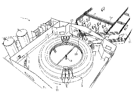
A parallel rotary parlour 1 according to the present invention is shown in
Figure 1 of the accompanying drawings. The parlour 1 comprises a rotatable
platform 3 having an annular shape and being provided with fifty milking
stalls 5
arranged side by side circumferentially along the platform 3. Since the
parlour 1
is of a parallel rotary type, the stalls 5 are arranged so that a cow 7 to be
milked
stands in a stall 5 facing radially inwards towards the centre 9 of rotation
of the
platform 3.
The platform 3 is rotated in an anti-clockwise direction as indicated by
arrow 11. This rotation is driven by means of a rotating wheel 13 which abuts
a
circumferential edge 15 of the platform 3 (see Figure 2). Specifically, in the
embodiment shown in the accompanying drawings, the drive wheel 13 abuts a
radially outer circumferential edge of the rotatable platform 3 and rotates in
a
clockwise direction as indicated by arrow 17. The wheel 13 is provided with a
tyre so as to assist in gripping the edge 15 of the platform 3 and thereby
ensure an
efficient transfer of rotary drive from the wheel 13 to the platform 3.
With reference to Figure 1, it will be understood that cows 7 to be milked
congregate in a holding bay 19 and walk onto the platform 3 one by one at a
stall
entry point 20. It will be understood that the speed of rotation of the
platform 3 is
sufficiently low for a cow 7 to step onto the platform 3 and walk into a
passing
stall 5. It will also be understood that, once a cow 7 has entered a stall 5,
further
rotation of the platform 3 closes the stall 5 so as to prevent the cow 7 from
backing
out of the stall 5. Each stall 5 is provided with four teat cups connected to
a
conventional milking system by means of hoses. As will be explained in more
detail below with reference to Figure 2, these teat cups 21a, 21b, 21c, 21d
are
CA 02705120 2010-05-06
WO 2009/063228 5
PCT/GB2008/003858
automatically attached to the teats 23a, 23b, 23c, 23d of a cow by means of a
robot
arm 25 which is moved by an electronic control system. Once the teat cups 21
are
attached to the teats 23, the cow 7 is milked in a conventional fashion whilst
the
platform 3 continues to rotate. Once milking has been completed, the teat cups
21
are removed from the teats 23 by means of an automatic teat cup retraction
system
(not shown) which pulls on the hose associated with each teat cup 21 and
withdraws the teat cups 21 back into a teat cup magazine 27.
Each stall 5 is provided with a teat cup magazine 27 which comprises four
recesses into which the four teat cups 23 locate when not in use. Each
magazine
27 is located adjacent the entrance of the associated stall 5 so as to not
unduly
hinder access by a cow 7 to the stall 5 and so as to be positioned adjacent
the rear
of a cow 7 stood in the stall. The magazine 27 will therefore be understood to
hold the teat cups 21 in a known storage position which is readily accessed by
the
robot arm 25 and which is sufficiently close to the teats 23 of the cow 7 to
allow
ready movement of the teat cups 21 to the teats 23 from the magazine 27.
Once the teat cups 21 have been retracted into the teat cup magazine 27,
the milking stall 5 in which the cow 7 is located will shortly thereafter move
to a
stall exit point 29 (see Figure 1). At the exit point 29, a stall 5 is
arranged in an
open configuration so that a cow 7 located therein may back out of the stall 5
and
leave the parlour 1 by means of an exit walkway 31.
As mentioned above, the rotary parlour 1 of the present invention is
provided with an automated system for attaching teat cups 21 to the teats 23
of a
cow 7 to be milked. This automated system comprises a robot arm 25 and an
electronic control system. The electronic control system allows movement of
the
robot arm 25 to be coordinated with the rotary movement of the platform 3.
More
specifically, the control system varies the speed of rotation of the platform
3 (by
varying the speed of the wheel 13) depending upon the rate at which the robot
arm
25 attaches teat cups 21 to the teats 23. Accordingly, if the robot arm 25
requires
more time than the current platform rotation speed allows in order to attach
all
four teat cups 21 to the teats 23 of a cow 7, then the electronic control
system will
slow the rotation of the platform 3 to allow the robot arm 25 additional time
before
the teat cups 21 and/or teats 23 move beyond the reach of the robot arm 25. If
CA 02705120 2010-05-06
WO 2009/063228 6
PCT/GB2008/003858
necessary, it will be understood that the electronic control system will stop
the
platform 3 rotation before the teat cups 21 and/or teats 23 move beyond the
reach
of the robot arm 25 so as to ensure the robot arm 25 is able to complete the
teat
cup attachment process. Accordingly, the platform 3 rotation speed is
determined
by the performance of the robot arm 25 and controlled by a closed loop
feedback
circuit. Once the robot arm 25 has attached all four teat cups 21 to the teats
23
after having slowed or stopped the platform rotation, the platform 3 will be
slowly
accelerated back to its original rotation speed. Alternatively, rather than
accelerating the platform 3 back to its original rotation speed, the platform
3 may
be accelerated to a speed less than the original rotation speed in the event
that the
control system determines the original rotation speed to be too high in the
circumstances.
In Figure 2 of the accompanying drawings, three milking stalls 5a, 5b, Sc
are shown moving past the robot arm 25. Alternative arrangements of robot arm
25 may be provided and the schematic example shown in Figure 2 is provided
merely for the purposes of illustrating the operation of the present
invention.
Specifically, the robot arm 25 shown in the accompanying drawings comprises
first and second arms 33, 35 rotatably connected relative to one another by
means
of an elbow joint 37. A teat cup gripper 39 for selectively gripping and
releasing a
teat cup is pivotally connected to the second arm 35 at a wrist joint 41. The
robot
arm 25 remains in a fixed location relative to the platform 3 but is
nevertheless
rotatable relative thereto about a central axis 43. As shown in Figure 2, the
robot
arm 25 is arranged in a fully extended configuration and the full reach of the
teat
cup gripper 39 when the robot arm rotates about the central axis 43 is
indicated by
arc 45.
With reference to Figure 2, it will be understood that the third milking stall
Sc has yet to move within reach of the robot arm 25. In contrast, the first
illustrated milking stall 5a has been within reach of the robot arm 25 for a
sufficient length of time for all four teat cups 21 to have been moved by the
robot
arm from the teat cup magazine 27 to the teats 23 of the cow 7. Teat cup hoses
47
are shown extending from the magazine 27 to the teat cups 21 attached to the
teats
23.
CA 02705120 2010-05-06
WO 2009/063228 7
PCT/GB2008/003858
With reference to the second milking stall 5b shown in Figure 2, it will be
understood that the teat cups 21 and teats 23 have only been within reach of
the
robot arm 25 sufficiently long for the first two teat cups 21a, 21b to be
attached to
the cow's teats 23a, 23b. The control system is such that the robot arm 25
grasps a
teat cup 21 at the earliest opportunity as soon as the magazine 27 moves
within its
reach. The grasped teat cup is then pulled from the magazine 27 and attached
to a
teat 23 (e.g. the first teat 23b to move within the reach of the gripper
indicated by
arc 45). The remaining teat cups 21 are then moved in turn by the robot arm 25
from the magazine 27 to the remaining three teats 23.
As explained in more detail below, the electronic control system
continuously or repeatedly monitors the platform in real-time. The electronic
control system monitors the speed and direction of rotation of the platform 3
and
also monitors the precise position of the platform 3. This information is used
to
determine the position of any one teat cup held by a teat cup magazine 27 so
that
the robot arm 25 may move directly to the magazine 27 and grasp a teat cup
from
the magazine 27 (perhaps with the assistance/guidance of a proximity sensor
once
the robot arm has moved to the locality of the teat cup magazine 27).
The parlour 1 is optimised so that the teat cups 21 and teats 23 associated
with a particular stall 5 remain within reach of the robot arm 25 only for the
average time it takes for all four teat cups to be attached to a cow 7. This
is
achieved by setting the platform rotation speed at a particular level. Thus,
it will
be understood that the final teat cup is generally attached just before the
final free
teat moves out of reach of the robot arm 25. Alternatively, the rotation speed
and
arm length may be such that the robot arm 25 completes the servicing of a
stall
(i.e. completes the teat cup attachment process) just as the next stall moves
within
reach of the robot arm 25. However, if the electronic control system
determines
that a particular teat cup has not been attached to its respective teat by the
time the
milking stall 5 has moved to the relevant predetermined position relative to
the
robot arm 25, then the speed of the platform rotation is reduced sufficiently
for the
robot arm 25 to revert back to the predefined schedule.
As explained above, the electronic control system may slow or stop the
platform 3 in order to ensure a teat cup is attached to a teat in accordance
to a
CA 02705120 2010-05-06
WO 2009/063228 8
PCT/GB2008/003858
particular attachment schedule. For example, it will be understood that, a
teat cup
attachment schedule may allow the robot arm 25 to delay attaching the final
teat
cup for as long as possible. In other words, the attachment schedule may
require
the final teat cup to be attached to the final free teat at a point just
before that teat
moves beyond the reach of the robot arm 25. If the electronic control system
determines that attachment has not been made, then the platform 3 will be
stopped
by the control system. Ideally, the electronic control system will first slow
the
platform rotation speed in order to provide the robot arm 25 with additional
time
for attaching the teat cup. If further time is required, then it will be
understood
that the platform may then be stopped (although it is generally preferred to
avoid
stopping the platform if possible). In this way, the electronic control system
may
accommodate delays in attaching a teat cup to a teat which may be caused by
unpredictable events such as movements of a cow within a stall.
More specifically, the electronic control system may store a predefined
schedule indicating by when (in terms of milking stall and/or teat position
relative
to the robot arm) a particular teat cup should be attached to a teat in order
for the
risk of a teat cup not being attached (before the teats move beyond the reach
of the
robot arm) to remain acceptable. Provided the risk of a teat cup not being
attached
to a teat remains acceptable, then the control system will maintain the speed
of the
platform. If any one of the teat cups is not attached in accordance with the
schedule, then the speed of the platform is reduced by the control system.
The=
control system may progressively further reduce the platform speed until the
teat
cup has been attached. It will be understood therefore that the performance of
the
robot arm in attaching teat cups in accordance with the teat cup attachment
schedule is constantly monitored. If the schedule is not complied with, then
corrective action is taken by the control system.
It will be further understood that, during the attachment process, the
location of a particular teat is determined in a conventional manner through
use of
appropriate sensing devices so that the robot arm 25 may identify a teat
location
and accurately complete the teat cup attachment.
It is mentioned above that the electronic control system monitors the speed
and direction of rotation of the platform 3 and also monitors the precise
position
CA 02705120 2010-05-06
WO 2009/063228 9
PCT/GB2008/003858
(i.e. angular position) of the platform 3. This allows the position of any one
teat
cup held in the teat cup magazine 27 to be more accurately determined and also
allows the robot arm to move a teat cup to an approximated initial position
adjacent the teat of a particular cow stood in the stall 5. The system
monitors the
movement of the platform 3 itself rather than movement of the drive wheel 13
and/or associated drive train. This is because there can be a tendency for the
drive
wheel to slip relative to the platform 3. Accordingly, the actual platform
speed
and position will generally not be accurately determined from monitoring
movement of the drive wheel 13.
The electronic control system monitors movement of the platform 3 itself
by means of two cameras 50, 52 located one above the other adjacent a radially
inner circumferential edge 54 of the platform 3 (see Figure 2). The two
cameras
50, 52 are each arranged to view a different one of two marker strips 56, 58
which
are each provided on the inner edge 54 and extend circumferentially along the
entire length of the inner edge 54 to form a closed loop (see Figure 3). The
two
marker strips 56, 58 are provided one above the other on the inner edge 54 and
each comprise an identical repeating pattern which is viewed by one of the
cameras 50, 52. Also, the identical repeating patterns of the two marker
strips 56,
58 are offset relative to one another. This offsetting of the two repeating
patterns
allows the direction of rotation of the platform 3 to be determined from a
comparison of signals generated by the two cameras 50, 52 in response to the
two
marker strips 56, 58.
One of the marker strips 56, 58 also may be provided with a unique
irregularity in the repeated pattern. Accordingly, since this irregularity
occurs at
only one position along the circumference of the inner edge 54, it will be
understood that the platform 3 will be in a particular rotary position when
the
irregularity is detected by one of the cameras 50, 52. In this way, the
precise
position of the platform 3 can be determined upon every complete rotation of
the
platform.
With reference to Figure 3, a portion of the inner edge 54 of the platform 3
is shown provided with an upper marker strip 58 and a lower marker strip 56.
Each marker strip 56, 58 is provided with a repeating pattern 62 comprising a
CA 02705120 2010-05-06
WO 2009/063228 1 0
PCT/GB2008/003858
comparatively dark portion 64 and a comparatively light portion 66. The
contrast
between the two portions 64, 66 is such that the two portions 64, 66 may be
distinguished from one another by a camera 50, 52. The two portions 64, 66
have
identical circumferential length and the offset 68 of the pattern between the
upper
and lower marker strips 56, 58 is one eighth of a pattern length 60. Also, an
irregularity in the repeated pattern of the upper marker strip 58 is provided
by a
comparatively dark portion 70 having a circumferential length three times that
of
the dark portion 64 of the regular pattern 62.
During operation of the platform, the first camera 50 views the lower
marker strip 56 and the second camera 52 views the upper marker strip 58. Both
cameras 50, 52 view the strips 56, 58 at the same circumferential position 72
along
the edge 54 of the platform, as shown in Figure 3. Accordingly, it will be
understood that, if the platform 3 rotates in the direction indicated by arrow
11 in
Figure 3, then a dark portion 64 of the upper marker strip 58 will be detected
by
the upper camera 52 before a dark portion 64 of the lower marker strip 56 is
detected by the lower camera 50. If the direction of rotation of the platform
3 is in
the opposite direction to that indicated by arrow 11, then the lower camera 50
will
detect a dark portion 64 before the upper camera 52 detects a dark portion 64.
Accordingly, it is possible for the electronic control system to determine the
direction of rotation of the platform 3 from the signals produced by the two
cameras 50, 52. Also, since the dark portions 64 of the lower marker strip 58
are
consistently spaced by the same known distance (i.e. by the comparatively
light
portions 66), the rate at which consecutive dark portions 64 are detected by
the
lower camera 50 allows the speed of rotation of the platform 3 to be
determined by
the electronic control system.
In addition, the detection of two dark portions 64 by the lower camera 50
when only a single dark portion has been detected by the upper camera 52
indicates that the upper camera 52 has detected the irregularity 70 in the
repeating
pattern of the upper marker strip 58 and this indicates to the electronic
control
system the precise position of the platform 3. Accordingly, the location of a
particular teat cup magazine 27 relative to the robot arm 25 may be determined
CA 02705120 2010-05-06
WO 2009/063228 11
PCT/GB2008/003858
and the need to adjust the speed of rotation may be calculated. If necessary,
the
direction of platform rotation may even be reversed.
In an alternative electronic control system shown in Figure 4, the two
cameras 50, 52 are located side by side rather than one above the other. The
arrangement is such that the first camera 50 monitors a particular first
location 102
past which a single marker strip 156 (mounted on the platform 3) moves upon
rotation of the platform 3, and the second camera 52 monitors a particular
second
location 104 past which the marker strip 156 also moves upon rotation of the
platform 3. The first and second locations 102, 104 are spaced from one
another
by a distance 106 which is not wholly divisible by the length 108 of a single
repeating pattern 110 or by a whole multiple of said length 108. In other
words,
the distance 106 between the two locations 102, 104 is not equal to the length
108
of a single repeating pattern or a whole number multiple thereof (said
distance 106
should not be equal to: pattern length x n; wherein n is a whole number, i.e.
pattern length x 1, pattern length x 2, pattern x 3, etc...). In the
particular
embodiment shown in Figure 4 of the accompanying drawings, the two cameras
50, 52 monitor locations 102, 104 spaced by a distance 106 equal to one and a
half
times the length 108 of a repeating pattern. The cameras 50, 52 could,
however,
be positioned so as to monitor locations spaced by a far greater distance than
this,
provided that this distance is not wholly divisible by a whole multiple of a
pattern
length, as mentioned above. For example, the two cameras 50, 52 could be
positioned at approximately diametrically opposite positions relative to the
platform 3.
It will be understood that, since the length 108 of a repeating pattern 110 is
known, the control system may be adapted to determine the speed with which the
marker 156 passes a location 102, 104 by reference to the rate at which either
one
of the cameras 50, 52 detects the movement of repeating patterns 110 past the
relevant monitored location 102, 104.
It will also be understood that the control system may be adapted to
determine the direction of movement of the marker 156 and, accordingly, the
direction of movement of the platform 3, by comparing what is being monitored
at
the first location 102 with what is being monitored at the second location
104. For
CA 02705120 2010-05-06
WO 2009/063228 12
PCT/GB2008/003858
example, with reference to Figure 4, it will be seen that the platform 3 is
positioned such that each camera 50, 52 will detect a light portion 62 of the
marker
strip 156. Upon movement of the platform 3 in the direction indicated by arrow
11, it will be understood that the dark portion 64 located between said two
light
portions 62 will move towards the first location 102 and, accordingly, into
the
viewing field of the first camera 52. The control system would then determine
from a comparison of the signals generated by the cameras 50, 52 that a dark
portion 64 has moved into the first location 102 whilst a light portion 62 of
the
marker strip 156 remains in the second location 104. On this basis, the
control
system will be able to deduce that the platform 3 has moved in the direction
indicated by arrow 11. Alternatively, if the platform moves in a direction
opposite
to that indicated by arrow 11, then the dark portion 64 located between said
two
light portions 62 will be detected by the second camera 52 monitoring the
second
location 104, whilst the first camera 50 will continue to detect merely a
light
portion 62 of the marker strip 156 at the first location 102. This different
result
from a comparison of the signals generated by the cameras 50, 52 distinguishes
opposite movements of the platform 3.
It will be understood that, although two separate cameras 50, 52 have been
described in relation to the systems shown in both Figures 3 and 4, the
locations at
which the or each marker strip is monitored may be arranged sufficiently close
to
one another as to fall within the field of view of a single camera. A person
skilled
in the art will appreciate that a suitable electronic control system will be
capable of
differentiating between the two locations being monitored, despite this
monitoring
being achieved with a single camera.
Although the repeating pattern of the above system has been described in
terms of light and dark portions 62, 64 detected by one or more cameras, it
will be
understood that a pattern may be provided by different means and/or monitored
by
a detector/sensor other than a camera. For example, the light portions may be
provided by means of one or more light emitting diodes (LED) and detected by
means of a photo-electric cell in place of the aforementioned cameras.
Alternatively, the repeating pattern may be generated by a plurality of
inductive
sources (for example, magnets) for inducing electric pulses in a detector
CA 02705120 2010-05-06
WO 2009/063228 13
PCT/GB2008/003858
comprising an inductive circuit. In other words, a transducer is provided
which
provides an electric signal indicative of the rotation (e.g. both speed and
direction)
of the rotary platform.
The present invention is not limited to the specific embodiments described
above. Alternative arrangements will be apparent to a reader skilled in the
art.
For example, the position of the platform 3 may be determined through the
provision of markers separate to the marker strips 56, 58. Each of these
additional
markers may be unique and placed at various positions along the circumference
of
the platform. In this way, detection of any one of the additional markers will
allow the position of the platform to be determined. The markers may, for
example, be numbers associated with each adjacent stall and which are detected
by
a camera and an associated electronic recognition system.