Note: Descriptions are shown in the official language in which they were submitted.
CA 02705543 2010-05-12
=
Description
Membrane Power Plant and Method for Operating the Same
The invention relates to a power plant and to a method for operating this
power plant.
The power plant is a membrane power plant comprising a high-temperature 02
membrane.
State of the Art
The separation of CO2 from typical coal power plant processes can, in
principle, be
achieved using three different concepts.
Post-combustion capture:
In this case, a conventional steam power plant is fed coal and air. Then, a
conventional
flue gas purification step follows. The CO2 is separated from the flue gas
after combustion by
using suitable scrubbing steps or, in the longer term, by membrane systems.
The disadvantage
of this method is that high volume flows of flue gas must be purified with
relatively low CO2
concentrations. Membranes for separating the CO2 therefore have high membrane
surface
requirements. Typical process parameters for the flue gas to be treated would
be 1000 m3/s with
18% by volume CO2.
Pre-combustion capture:
This method is based on an IGCC (integrated gasification combined cycle)
process,
wherein the separation of CO2 is carried out in an intermediate step after
coal gasification or
natural gas reformation, and after the gas purification and gas conditioning
(CO shift) steps, but
before the combustion step using air. The different coal gasification methods
developed so far
are preferably operated with oxygen or enriched air (and steam) at a pressure
of approximately
20 to 30 bar. For this reason, coal gas has two crucial advantages with
respect to CO2
separation. For one, the real volume flow, at a low nitrogen level and high
pressure, is
approximately 100 times lower than for the flue gases of conventional steam
power plants. The
direct result is high partial pressures for the main components, CO and H2.
After additional CO conversion into CO2 and H2 by supplying steam (shift
reactor) in
order to condition the carbon gas for CO2 separation, two options are
available, which are the
separation of CO2, such as by way of a scrubber, or the separation of a
sufficient quantity of H2
CA 02705543 2010-05-12
=
using a membrane, wherein gas that is rich in CO2 and suited for liquefaction
and storage
remains in the retentate. With both options, the hydrogen can subsequently be
turned into
electric energy in a gas and steam power plant (gas combined cycle), for
example, by using an
H2 turbine. Typical process parameters after the gas purification would be 10
m3/s with 45% by
volume CO2.
Oxyfuel process:
In this case, simple CO2 separation is carried out by way of condensation
after
combustion of the coal in a boiler using pure oxygen and a subsequent step of
flue gas
purification. This method has a crucial advantage. The only combustion
products resulting from
a combustion process in pure oxygen are CO2 and water vapor, which can be
easily separated
from CO2 by condensation as the gas mixture cools. The CO2 and water vapor are
advantageously recycled in a circuit and recirculated to the boiler together
with the oxygen flow.
The pure oxygen can either be generated by conventional cryogenic air
separation or by using
an 02 membrane, wherein the returned (circulated) CO2/water vapor mixture can
serve as a
flushing gas.
In all three cases, however, no well-functioning concept yet exists for the
specific CO2
separation.
High-temperature 02 membranes reportedly have tremendous development
potential,
particularly in terms of energy. As a condition for this, cost-effective
membranes must be
available.
For these applications, so-called dense mixed conductors, such as perovskite,
may be
used. In these, the 02/N2 gas separation is not effected by the separating
action of pores, but by
the special transport mechanisms in the bulk material. Oxygen ions migrate in
the direction of
the concentration gradients thereof. On the membrane surface, the electrons
leave the oxygen
ion and migrate back.
The challenges in the development of the membrane and membrane module as well
as
in the development of the concept are to achieve the highest degree of
separation possible, the
highest purity of separated components possible, and the lowest energy
expenditure possible
during the conditioning of the feed gas and the permeate flow, such as by
increasing pressure
or using a vacuum. This is intended to achieve low losses in net efficiency,
while at the same
time achieving the highest flow density possible for the permeating component.
At the same
time, focus is placed on low surface requirements for the membrane and the
lowest apparatus-
related costs in the membrane surroundings, thus requiring little additional
investment costs.
2
CA 02705543 2010-05-12
Finally, the desire is to create a module and method concept, which also meets
strict
requirements in terms of stability and service life, in light of the high
operating temperatures.
These requirements are very complex and, in part, contradictory. As a result,
high
demands in the form of high permeability and selectivity are placed on the
membranes used, as
well as on the process engineering, in terms of providing favorable process
conditions in an
optimal membrane separating process, with low additional process engineering
costs.
In the problem stated, three fundamental boundary conditions must notably be
observed:
1. Non-porous, dense mixed-conductive 02 membranes are subject to a law
(Wagner
equation), according to which the local 02 permeate flow densities are
proportional to the
natural logarithm of the particular partial pressure conditions of the
permeating component, that
is 02 (feed side/permeate side of the membrane). Only in the case of extremely
thin membranes
are surface effects added to this bulk transport mechanism, whereby the
dependency on the
pressure conditions is less pronounced.
2. As differs from porous membranes, no special measures are required with
respect to
the required purity of the 02 product flow, because the 02/N2 selectivity of
dense, mixed-
conductive membranes is excellent by nature, and is about 100:1 or higher.
3. The inevitably high membrane operating temperature, which is typically 800
C, is a
particular challenge with respect to the design and concept. This is further
exacerbated for
power plant designs that are directed at achieving pressurized operation of
the high-
temperature membrane and the high-temperature heat exchangers of the membrane
surroundings.
As no membrane power plant exists to date, the prior art consists of no more
than
conceptual proposals in the literature. The concept developments are still in
the early stages.
The literature discloses basic circuits, however in each case only a single
special membrane is
examined. Likewise, in graded processes, only one membrane is used for the
separations to be
carried out on the particular gas flows in the cascade stages. With this
individual membrane, the
partial pressure of the permeating component decreases continuously, but the
feed pressure
and permeate pressure are constant over the entire membrane length, unless a
flushing gas is
used. These pressures can optionally be adjusted by way of a compressor or
vacuum pump.
The following concept is known from the prior art for an oxyfuel power plant
technology
having conventional 02 separation from the air, which is the so-called cryogen
air separation
plant (LZA) by Vattenfall. Presently, a 30 MWth plant is under construction.
FIG. 1 shows a
schematic diagram of such an oxyfuel power plant having an upstream air
separation system.
In the oxyfuel process, coal is not burned with air, but in an atmosphere of
pure oxygen
3
CA 02705543 2010-05-12
and recycled flue gas. Ash is precipitated in the following treatment steps,
as in the conventional
power plant process. The fly ash is then separated by dedusting. In the
oxyfuel process, a large
portion, up to 75% of the flue gas produced during combustion, is recirculated
to the boiler in the
form of CO2 and water vapor. Sulfur compounds are extracted from the flue gas
flow in the form
of gypsum as by-products by way of desulfurization. Finally, the remaining
water vapor that was
added with the coal is condensed out, so that the remaining flue gas comprises
almost
exclusively pure CO2. The carbon dioxide can then be compressed to more than
100 bar for
further use and/or storage.
The disadvantage of this concept is the high energy requirement of the
cryogenic air
separation system (LZA), whereby a loss of efficiency of at least 10
percentage points (including
CO2 liquefaction) is to be expected. A brown coal power plant according to the
present state of
the art, for example, has a net efficiency of 43%. If, based on this
technology, one were to
employ the oxyfuel process with the cryogenic air separation system, an
efficiency of only 35%
would be likely.
A possible variant of the oxyfuel power plant technology with the 02 membrane
is
presently under development in the OXYCOAL-AC project. A characteristic
feature is the
membrane mode of operation, using two process engineering measures in order to
achieve high
propulsive forces for the permeate flow. First, the air on the feed site is
compressed to
approximately 20 bar in order to increase the 02 partial pressures to
approximately 2 to 4 bar,
and secondly, flue gas flushing is used in the counter-current on the permeate
side (1 bar) in
order to lower the 02 partial pressures (approximately 30-300 mbar). This
creates the
advantage of high local 02 partial pressure conditions of typically 13:1 (4
bar/0.3 bar) or higher.
On the other hand, the pressurized operation and the flue gas membrane
flushing result
in a number of disadvantages, which can be listed as follows:
- two large volume flows must both enter the membrane at the membrane
operating
temperature, because otherwise the membrane temperature cannot be maintained;
- hot flue gas recirculation causes a high recirculated volume flow, because
the cooling
effect is generally not effective;
- hot gas purification is required;
- the high pressure gradient between the feed side and permeate side of the
membrane
results in very high stability requirements for the membrane module;
- the high pressure gradient between the feed side and permeate side of the
membrane
results in very high stability requirements for the high-temperature
recuperative heat exchanger
used for air preheating;
4
CA 02705543 2010-05-12
=
- the residues of the combustion products reach the permeate side of the
membrane;
- the CO2 atmosphere on the permeate side limits the membrane selection, for
example,
barium-containing perovskite membranes exhibit the highest 02 flow densities,
but have stability
problems in a CO2 atmosphere.
Problem and Solution of the Invention
It is the object of the invention to provide a process for operating an
oxyfuel power plant
having an 02 membrane, which overcomes the disadvantages described above,
which is to say
that it results in the lowest possible apparatus-related cost in the membrane
surroundings. The
basic requirements for the process remain, such as the highest possible degree
of separation of
CO2 from the flue gas, and the highest possible purity of the separated
component at the lowest
possible energy expenditure, which is to say, the highest possible net
efficiency.
In addition, the method of the separating process is to enable the highest
possible flow
density for the permeating component. Additionally, it is an object of the
invention to create an
apparatus that is suited for carrying out said method.
The objects of the invention are achieved by a method for operating an oxyfuel
power
plant having a high-temperature 02 membrane according to the main claim and by
an apparatus
according to the additional independent claim. Advantageous embodiments of the
method and
the apparatus are disclosed in the dependent claims.
Subject Matter of the Invention
The invention is based on the concept of the oxycoal process, wherein coal is
burned
using pure oxygen, the waste gas is purified in the hot state, and the CO2 is
separated after
cooling, while the remaining hot flue gas is fed to a high-temperature 02
membrane. The
necessary oxygen is obtained by separation from compressed air by way of this
membrane. The
flue gas enriched with oxygen is subsequently once again recirculated to the
combustion
process.
Unlike in the process described above, however, the following mode of
operation is
proposed. The feed side of the 02 membrane is operated with atmospheric air.
Preheating is
carried out by recuperation over nearly the entire temperature range,
typically in the range of 20
to 750 C. Usually, only a small amount of natural gas must be supplied for
final preheating from
approximately 750 to 800 C. As an alternative, final preheating of the air
could take place in the
steam generator. From a present-day perspective, useful membrane temperatures
range
between 700 and 1000 C.
CA 02705543 2010-05-12
Flushing of the membrane on the permeate side with recirculated flue gas is
eliminated,
because this gas generally comprises residues of combustion products from the
coal burning
process, which could be disadvantageous for the membrane.
According to the invention, the permeate side is accordingly subjected to a
vacuum, in
order to achieve lower 02 partial pressures on this membrane side during
operation than on the
feed side. On a large scale, for example, a vacuum pressure level of 30 mbar
can be generated
using a conventional vacuum pump. The oxygen is then conducted into the
oxyfuel block at
atmospheric pressure (1 bar).
Compared to the OXYCOAL-AC concept, the mode of operation according to the
invention disadvantageously results in lower 02 partial pressures at the
membrane, typically in
the range of 3:1 to 7:1, instead of the conditions of approximately 13:1 and
67:1 occurring
otherwise.
However, with the invention, it is advantageously possible to eliminate all of
the technical
problems associated with the concept described above, using pressurized
operation and
membrane flue gas flushing. The air can now be preheated in a simple manner
over nearly the
entire temperature range by way of recuperation (typically 20-750 C), at
uniform pressure levels
for the inflowing and outflowing air. In the case of the membrane power plant
designs using
pressurized operation on the feed side of the membrane, a subsequent automatic
expansion
exists, which results in cooling. In these cases, a different major heat
source must be found or
provided, for example, hot recirculated flue gas or coal combustion directly
in the steam
generator.
In the vacuum range of the gas circulation, unacceptably high pressure losses
are not a
problem that must be feared, because the 02 gas volume is lower than the air
volume by a
factor of approximately 10. The 02 generation is now no longer substantially
integrated in the
oxyfuel combustion process. For the development of the overall power plant,
this means:
1. The 02 membrane block can be developed separately, with only the membrane
module not yet being available today.
2. After development of the oxyfuel block, such as by VATTEN FALL (initially
using the
air separation system), this can be combined into an oxycoal membrane power
plant, with only
available power plant components being adapted to each other.
The extraction of 02 by way of a vacuum pump is comparable to the extraction
of CO2 in
the post-combustion power plant using a CO2 membrane at the cold flue gas end.
Initial
estimates for the energy requirement of the vacuum pump, for example, indicate
that the
efficiency losses (including CO2 liquefaction) will be approximately 6%
(vacuum pump and CO2
6
CA 02705543 2015-09-08
70577-150
liquefaction approximately in equal portions).
According to an embodiment, there is provided a method for operating a
power plant, in which coal is burned using substantially pure oxygen and the
combustion waste gas is purified and partially recirculated to the combustion
process,
characterized in that the oxygen that is used is obtained by separation from
air using
a high-temperature 02 membrane, wherein on the feed side the membrane is
operated with atmospheric air at a pressure of up to 2 bar and on the permeate
side a
negative pressure of between 0.02 and 0.5 bar is applied.
According to another embodiment, there is provided a power plant for
generating electrical energy, comprising a combustion chamber for producing
steam,
at least one downstream flue gas purification stage, a separation stage for
002, a
recycling circuit for the flue gas, and a high-temperature 02 membrane, which
is
connected upstream of the combustion chamber, characterized in that: the high-
temperature 02 membrane has a inlet and an outlet on the feed side, which are
thermally coupled by way of a heat exchanger, and on the permeate side the
high-
temperature 02 membrane has only an outlet, which is connected to the
combustion
chamber and/or the flue gas recycling circuit, and a means for cooling and/or
compression is disposed in this outlet.
Brief Description of the Drawings
Fig. 1:
Oxyfuel Process: Combustion of coal with pure oxygen which is
generated in an air separation plant. Part of the flue gas from the combustion
process
is recirculated in order to control the combustion temperature.
7
CA 02705543 2015-09-08
70577-150
Fig. 2:
Oxycoal Process: Combustion of coal with oxygen which is generated in
a high temperature membrane. Part of the flue gas from the combustion process
is
used as flushing gas on the permeate side of the membrane.
Fig. 3:
Combustion of coal with pure oxygen which is generated in a high
temperature membrane. Oxygen is extracted from atmospheric air and penetrates
through the membrane. Instead of flushing gas a vacuum is generated on the
permeate side of the high temperature membrane.
Specific Description
The invention will be described in more detail hereinafter based on
figures and exemplary calculations, without thereby limiting it to the
embodiments
mentioned above.
In FIGS. 1 to 3 the following meanings apply:
1 Steam boiler,
2 Purification of the waste gas, generally comprising dedusting and
removal of nitrogen,
3 Condensation of the flue gas,
4 Air separation system
5 High-temperature 02 membrane (OTM = oxygen transport
membrane)
6 Recuperative heat exchanger
7 Circulation fan
7a
CA 02705543 2015-09-08
70577-150
8 Compressor, vacuum pump
(A) Optional heater, such as a burner
FIG. 1 shows the concept of the oxyfuel process. The coal is burned in
an atmosphere comprising pure oxygen and recycled flue gas in the combustion
boiler (1). Electricity is produced from the steam that is generated. The
combustion
waste gas is dedusted and nitrogen is removed in the subsequent purification
steps
(2). The majority of the flue gas produced during combustion is recirculated
into the
combustion boiler (1) in the form of CO2 and water vapor at temperatures
around
200 C. The remaining water vapor that was added with the coal is condensed out
(3),
so that approximately pure CO2 can be separated. The oxygen that is used is
generated cryogenically in an air separation system (4).
FIG. 2 illustrates the oxycoal method. Again, the coal is burned in an
atmosphere comprising pure oxygen and recycled flue gas in the combustion
boiler
(1). Electricity is produced from the steam that is generated. The combustion
waste
gas is dedusted and nitrogen is removed in the hot stage in the subsequent
purification steps (2). The flue gas, however, is recirculated in the form of
CO2 and
water vapor to a high-temperature 02 membrane (5), in which the flue gas is
enriched
with oxygen. The oxygen is extracted from the air, which is initially
compressed to 20
bar using a compressor (8). The air is heated to approximately 400 C in the
process.
A recuperative heat exchanger (6) preheats the air that is supplied to the
high-
temperature 02 membrane to approximately 750 C using the flue gas exiting the
membrane.
7b
CA 02705543 2010-05-12
The depleted air is expanded again and discharged. The flue gas enriched with
oxygen is
returned to the combustion boiler (1).
The disadvantage is that large amounts of gas to be purified are produced
during the hot
flue gas recirculation. The heat exchanger must be designed for pressures of
up to 20 bar and
for differential pressures of up to 19 bar. In addition, it is a disadvantage
that, together with the
flue gas, combustion products reach the oxygen membrane, and the high CO2
portion in the flue
gas also has a limiting effect on the membrane selection.
The following standard values can be provided as examples of the conditions in
the
high-temperature 02 membrane:
pFoe: d
3 2 bar
-
P0
Permeat 0,3 0,15 0,03 bar
, ...permeal
The ratio of the oxygen partial pressures f-'492 " Pch in the membrane
ranges
between 10:1 and 80:1, and notably, high values in the permeate outlet region
of between 15:1
and 20:1 are considered to be particularly advantageous.
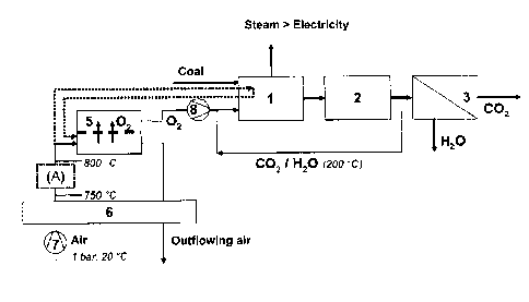
FIG. 3 illustrates the concept of the mode of operation of a coal-operated
power plant
according to the invention. In a manner similar to that of the oxycoal
process, a high-
temperature 02 membrane (5) is used for generating the required oxygen. In
order to avoid the
disadvantages described above, however, the flue gas is recirculated to the
combustion
chamber (1) directly after purification at a temperature of approximately 200
C, in a manner
similar to that of the oxyfuel process.
One of the differences, as compared to the prior art described above, is that
the air is
supplied on the feed side of the high-temperature 02 membrane (5) at
atmospheric pressure,
and that a negative pressure is automatically adjusted on the permeate side
for the oxygen
transfer. In this way, pure oxygen is produced on the permeate side, which
subsequently, after
cooling and compression, is supplied directly to the combustion chamber, or,
as an alternative,
first to the recycled flue gas. The preheating of the air is again achieved by
heat transfer (6)
from the air exiting the membrane, but here further preheating by an external
burner (7) as well
as preheating directly by the combustion chamber (1) can also optionally be
performed.
The following standard values can be provided as examples for the conditions
in the
transport membrane during this mode of operation for an oxycoal membrane power
plant using
a high-temperature 02 membrane having a permeate vacuum (OXYVAC-JUL).
8
CA 02705543 2010-05-12
The ratio of the oxygen partial pressures 02
( p feed Zu pber2mrat
in the membrane should
advantageously range between 10:1 and 2:1, and values between 7:1 and 3:1 are
considered to
be particularly advantageous.
peed
200 100 mbar
30 30 mbar
Preat ____________________
In order to estimate possible permeate flow densities with respect to the
membrane
surface requirement, exploratory measurements were conducted on a barium-
containing
perovskite BSCF5582 (thickness 1 mm, no substrate). The vacuum pressure of 30
mbar was
approximately simulated by adjusting to 02 partial pressures of approximately
30 mbar using
helium flushing gas. An 02 flow density of 2 Nm3/m2h was measured. This is
already within the
range of the target value (6 Nm3/m2h).
This target value appears achievable by reducing the membrane thickness as
well as by
optionally reducing any existing major surface resistance, which will dominate
when the
thickness is reduced, by way of roughening and/or doping using catalytically
active substances.
Finally, in order to illustrate the technical and economical potential of this
membrane
power plant technology, a simple estimation will be provided. For a 1000 M
oxycoal power plant
(02 requirement of approximately 200 kg/s, or 140 Nne/S, or 500,000 Nm3/h), a
membrane
surface of 100,000 m2 is required for a target 02 flow density value of 5
Nm3/m2h. In Germany,
the total power plant output is approximately 100 GW. If these power plants
were replaced by
oxycoal power plants and the membrane surface were related to the population,
the following 02
membrane surface and mass requirements would be obtained (for a membrane
thickness of
approximately 1 mm):
= approximately 0.1 m2/inhabitant
= approximately 0.5 kg/inhabitant
Since the power plant output is approximately 1 kw/inhabitant, the same
numbers are
obtained for the 02 membrane with respect to 1 kW (power plant output):
= approximately 0.1 m2/kW and
= approximately 0.5 kg/kW.
Membrane manufacturers estimate the investment costs for these ceramic
membranes
to be approximately Ã1000/m2 for prototypes and Ã200/m2 for mass production.
For a 1000 MW
power plant with an investment amount of approximately Ã1 billion,
approximately Ã20 million
would be added for the membrane module, plus the investment costs for the heat
exchanger,
9
CA 02705543 2010-05-12
vacuum pumps, CO2 compressor and CO2 pipeline, for example.