Note: Descriptions are shown in the official language in which they were submitted.
CA 02705678 2010-05-27
VAPOR BARRIER FOR FLAMMABLE LIQUID STORAGE TANKS
CROSS-REFERENCE TO RELATED APPLICATION
[0001] This application claims the benefit of U.S. Provisional Patent
Application Serial No. 61/213,265, filed May 21, 2009.
BACKGROUND OF THE INVENTION
1. FIELD OF THE INVENTION
[0002] The present invention relates to storage tanks for flammable
liquids, and particularly to a vapor barrier for flammable liquid storage
tanks
that provides a vapor impermeable barrier layer with fire-suppressing
capabilities for covering a surface of the flammable liquid.
2. DESCRIPTION OF THE RELATED ART
[0003] Flammable liquids, such as oil, gasoline and the like, must be
stored in specialized storage tanks due to the flammable vapor that forms
above the liquid surface. A common storage tank, often used in the
petrochemical industry, is the "floating roof' tank. A typical floating roof
1
CA 02705678 2010-05-27
tank is illustrated in Fig. 2. Tank 100 includes a hollow cylindrical housing
1 12 having an open upper end. The open upper end is seated by a buoyant
cover 114, having a circular contour matching the dimensions of the interior
of housing 112. Cover 114 floats on the flammable liquid L contained within
the housing 112, thus providing a seal between the surface of the liquid L
and the outside environment, preventing the buildup of flammable vapor
(and exposure thereof to external hazards, such as sparks).
[00041 Typically, the cover 114 is fabricated from metal and has a
hollow chamber divided by walls into an array of pontoons in order to
provide sufficient flotation to carry the weight of the cover plus additional
weight, such as the weight of snow which might form on the cover 114. In
older oil tank equipment, the cover was constructed of a metal plate with
pontoons mounted beneath the cover plate, while modern tanks typically
have the pontoons located above the metal cover plate. Repairs to the cover
may require welding equipment, which can be used only after the tank has
been taken out of service in order to ensure that the cover is clean and that
there are no flammable vapors present. If any flammable vapors are present
2
CA 02705678 2010-05-27
during repair work on the cover, such as the repair of a pontoon of the cover,
a spark from the welding may ignite an explosive burning of the vapor.
[0005] Repairs may also be made without taking the tank out of service.
For example, one of the pontoons may sustain a relatively small opening
through which liquid can seep resulting in a loss of buoyancy. By means of
an access port, a person may enter the pontoon and apply foamed urethane
plastic as a liquid that later hardens to maintain buoyancy. Use of the
plastic
is not intended as a permanent repair because the plastic may become
impregnated with the flammable liquid. Further, the plastic is
disadvantageous because, at the conclusion of the service interval when
reconditioning is mandatory, it is very difficult to remove the plastic so as
to
be able to clean the cover and make any permanent repairs. Obviously,
welding cannot be employed for repair until all liquid and liquid soaked
flotation, such as the foamed plastic, has been removed.
[0006] As an alternative procedure of repair, one might consider
insertion in the pontoons of hollow, non-foamed plastic bodies to provide
sufficient buoyancy so that it is not necessary to repair the leak in the
3
CA 02705678 2010-05-27
pontoon. However, the use of a plastic hollow body, such as a hollow ball,
has been avoided in the petrochemical industry because such a plastic body
is electrically insulating and susceptible to developing a static electric
charge.
There is a danger that the flotation body may suddenly discharge via a spark,
which can ignite an explosion.
[0007] Additionally, in the past, foam products have also been applied
to the surfaces of flammable liquids, creating an effective vapor seal between
the flammable liquid and the vapor space thereabove. However, the foam
degrades within a short period of time, thus defeating the desired
suppression qualities. Moreover, foam applied in the event of a flammable-
liquids fire is the traditional form of fire fighting, with the intent of the
foam
being to cool the surface of the liquid and to also separate the flammable
liquid from contact with oxygen, thus suppressing the fire. The difficulty
with this traditional method of using foam is that the strong convective hot
air currents caused by the fire tend to displace the foam, thus exposing the
flammable liquid to the existing fire.
4
CA 02705678 2010-05-27
[0008] Further, marine vessels currently do not typically employ any
physical barrier between a stored flammable liquid and the vapor space
formed thereabove. Typically, such vessels employ inert gas generators that
create an oxygen-deficient gas that is maintained above the flammable liquid
in order to preclude the flammable vapor from mixing with oxygen that
might otherwise create a flammable atmosphere. Such systems, however, do
not provide backup prevention in case the gas generator fails.
[0009] Thus, a vapor barrier for flammable liquid storage tanks solving
the aforementioned problems is desired.
SUMMARY OF THE INVENTION
[0010] The vapor barrier for flammable liquid storage tanks provides a
gas impermeable layer for covering the surface of a flammable liquid stored
within a conventional flammable liquid storage tank. The vapor barrier
further provides fire-suppression capabilities, and it should be understood
that the vapor barrier may be applied to tankers, vessels, barges or any other
type of container for flammable liquids. The vapor barrier prevents the
build-up of flammable vapors over the flammable liquid surface. The vapor
CA 02705678 2010-05-27
barrier is formed from a plurality of spherical buoyant members. Each
spherical buoyant member has a heat-resistant core or shell, a heat-reactive
intumescent or flame retardant layer formed on an outer surface of the heat-
resistant core or shell, and an antistatic layer formed on an outer surface of
the heat-reactive intumescent layer. The antistatic layer is also preferably
formed from an oil-phobic material. Further, each spherical buoyant
member has a specific gravity selectively chosen so that the spherical
buoyant members float at a desired level within the flammable liquid.
[0011] These and other features of the present invention will become
readily apparent upon further review of the following specification and
drawings.
BRIEF DESCRIPTION OF THE DRAWINGS
[0012] Fig. 1 is an environmental front view of a flammable liquid
storage tank, the tank being broken away to show a vapor barrier for
flammable liquid storage tanks according to the present invention deployed
therein.
6
CA 02705678 2010-05-27
[0013] Fig. 2 is a perspective view of a flammable liquid storage tank
according to the prior art, broken away to show a portion of the interior of
the tank and contents thereof.
[0014] Fig. 3 is an environmental, partial side view of the vapor barrier
for flammable liquid storage tanks according to the present invention.
[0015] Fig. 4 is a section view of a single buoyant member of the vapor
barrier for flammable liquid storage tanks according to the present invention.
[0016] Fig. 5 is an environmental, diagrammatic front view of an
alternative embodiment of a vapor barrier for flammable liquid storage tanks
according to the present invention.
[0017] Similar reference characters denote corresponding features
consistently throughout the attached drawings.
DETAILED DESCRIPTION OF THE PREFERRED EMBODIMENTS
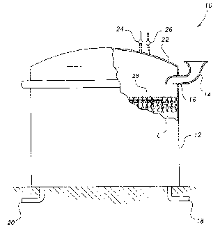
[0018] Referring to Fig. 1, an exemplary storage tank 10 has a vapor
barrier for flammable liquid storage tanks deployed therein, the barrier being
designated generally as 28. In addition to simply preventing the escape of
vapor, the vapor barrier further provides fire suppression capabilities, and
it
7
CA 02705678 2010-05-27
should be understood that the vapor barrier may be applied to storage
tankers, vessels, barges or any other type of container for flammable liquids.
The liquid storage tank 10 is shown for exemplary purposes only and
includes elements conventionally found in storage tanks for flammable
liquids, such as oil, gasoline and the like. The housing 12 may be formed
from steel or the like, as is conventionally known, and is either supported
above the ground surface, or is at least partly buried in the ground. The tank
is provided with a cover 22 and with pipes 18 and 20 for admitting
flammable liquid L into the open interior region of housing 12, and for the
withdrawal thereof when required. It should be understood that the vapor
barrier 28 may be used with any suitable type of flammable liquid L, such as
liquid natural gas, petroleum oil, gasoline or the like.
[0019] The surface of the liquid L is provided with at least one layer of
buoyant bodies or spheres forming the vapor barrier layer 28, as will be
described in greater detail below. The cover 22 may be further provided with
a vent 26 and/or with an admission valve 24 for admitting an inert gas to the
space above the stored liquid L, as is conventionally known. Preferably, a
s
CA 02705678 2010-05-27
port 16 is formed through the sidewall of the housing 12, allowing the
selective insertion of the vapor barrier layer 28 (in the form of individual
spherical members, as will be described below) within the housing 12 via a
chute 14. It should be understood that the chute 14 is shown for exemplary
purposes only. It should be further understood that the vapor barrier layer
28 may be introduced into housing 12 in any suitable manner, such as, for
example, through existing tank openings. Port 16 and chute 14 are shown
for exemplary purposes only.
[00201 As best shown in Fig. 3, the vapor barrier 28 is preferably
formed as a buoyant layer through the stacking of multiple sizes of buoyant
members 30, 32, 34. Each buoyant member 30, 32, 34 is preferably
spherical, the buoyant members 30 having the largest radii, the buoyant
members 34 having the smallest radii, and the buoyant members 32 having
radii therebetween. It should be understood that the relative dimensions
illustrated in Fig. 3 are shown for exemplary purposes only, and that a wider
variety of buoyant members having distinct radii may be utilized.
9
CA 02705678 2010-05-27
[0021] The spherical contour of the buoyant members 30, 32, 34 allows
for a stacked, interlocking arrangement, as shown in Fig. 3, the buoyant
members naturally settling under the force of gravity into a gas-impermeable
layer when inserted into the housing 12 to float on the surface of flammable
liquid L. The specific gravity of the buoyant members 30, 32, 34 is
preferably in the range of between 0.05 and 0.5 so that the buoyant
members 30, 32, 34 will remain partially submerged within liquid L, as
shown, when flammable liquid L is a common flammable material, such as
petroleum oil or gasoline. It should be understood that the specific gravity
may be varied, depending upon the particular composition of the flammable
liquid L. The specific gravity is selected such that the buoyant members are
partially submerged so that the buoyant members provide a lower cross-
sectional area below the level of the liquid L in the event of thermal wind
currents or convective thermal air currents generated within the tank 10 in
the event of a fire.
[0022] As shown in Fig. 3, the differently sized buoyant members 30,
32, 34 forming the vapor barrier layer 28 form a suppressing blanket effect
CA 02705678 2010-05-27
for the surface of liquid L, minimizing possible liquid-vapor contact within
tank 10 (of Fig. 1). The smaller spherical bodies 32, 34 fill in gaps between
the larger bodies 30, thus blocking potential evaporation paths from the
surface of the liquid L. Additional layers create interstitial vapor pockets,
trapping vapors therein and preventing the release thereof into the area
above the vapor barrier 28.
[0023] As shown in Fig. 4, each buoyant member is preferably formed
from three layers. A single buoyant member 30 is shown in Fig. 4, although
it should be understood that buoyant members 32, 34 are formed from
identical materials, although having differing radii. The central layer or
core
40 is formed from a material that is non-reactive to petroleum products and
that can withstand temperatures of approximately 350 OF or greater without
melting. Although shown as being solid, it should be understood that core
40 may also be in the form of a hollow shell or the like. The core 40 may be
coated with an intumescent layer 38. In the event of a fire within tank 10 of
Fig. 1, the intumescent layer 38, which is heat reactive, expands, thus
ensuring that buoyant members 30, 32, 34 form a vapor-impermeable
11
CA 02705678 2010-05-27
barrier. Alternatively, the intumescent layer 38 may be replaced with a
flame-retardant material, thus providing protection for the core 40. Heat-
reactive, expanding foam materials that are non-reactive with petroleum
products and that can withstand relatively high temperatures are well known,
and any suitable heat-reactive intumescent material (or, alternatively, flame
retardant material) may be utilized. in use, the smaller buoyant members, as
best illustrated in Fig. 3, fall into the spaces between the larger buoyant
members, thus forming a nearly continuous barrier against escaping vapor.
This continuous barrier acts as a floating roof for preventing escape of the
flammable vapor. In use, with liquid natural gas or a similar substance,
which is a liquid at cryogenic temperatures, the vapor barrier 28 forms a
thermal insulation layer, preventing the cryogenic liquid from boiling off too
quickly.
[0024] As noted above, alternatively, the middle layer 38 (best seen in
Fig. 4) may be formed from any suitable flame retardant material, the flame
retardant material replacing the intumescent material. The outer layer 36 is
formed from oil-phobic and antistatic material. Layer 36 is preferably
12
CA 02705678 2010-05-27
further hydrophobic. The outer layer 36 may be formed from, for example, a
high-density plastic resin mixed with an antistatic additive or agent. The
antistatic agent is effective in converting the electrically insulating
plastic
into an electrically conductive material that does not develop a static
electrical charge. Antistatic materials are well known. One example of such
a material capable of being mixed with a high-density plastic resin is
manufactured under the mark GLYCOSTAT, manufactured by Lonza of Fair
Lawn, NJ. It should be understood that the core 40, the intumescent or fire
retardant layer 38, and the oil-phobic and antistatic layer 36 may be formed
from any suitable materials, preferably so that the overall structure has a
specific gravity within the range of approximately 0.05 and 0.5.
[0025) The spherical buoyant members 30, 32, 34 may have any desired
size, although in the preferred embodiment, the diameters of the buoyant
members are preferably within the range of approximately 1/16 of an inch to
four inches. It should be understood that members 30, 32, 34 may include
all three layers of material, or may include any combination thereof. For
example, intumescent or flame retardant coating 38 is preferably applied at a
13
CA 02705678 2010-05-27
relatively large thickness, and thus may only be able to be applied to the
largest members 30 in order to maintain buoyancy. In this example,
members 32, 34 would only include the core 40 and the antistatic and oil-
phobic coating 36. Alternatively, the intumescent or flame retardant material
may be used as an outer shell for the spherical members, rather than being
solely formed in the core. It should be understood that any combination of
the above-described layers and materials may be used, depending upon the
liquid and the container.
[00261 Fig. 5 illustrates an alternative embodiment of the vapor barrier
in which the vapor barrier layer 28 is combined with the conventional floating
roof 1] 4 of Fig. 2. Conventional floating roofs are typically formed as
circular pans having a planar floor and a raised peripheral rim defining an
open interior region in the upper side thereof. Such roofs may sink due to
environmental conditions, such as earthquakes or other external stresses,
causing the pan to tilt and thus fill with liquid L. Some floating roofs
include
a central drain, but this can become clogged by snow or ice, for example.
14
CA 02705678 2010-05-27
[0027] In Fig. 5, a floating roof 114 is positioned within the tank, as in
Fig. 2, but with a bag 31 containing members 30, 32 and 34 positioned
within the open interior region thereof. The bag 31 is formed from a readily
dissolvable material so that if floating roof 1 14 sinks, the bag 31 will
dissolve
in liquid L and a vapor barrier layer 28 will cover the surface of liquid L as
described above, thus adding an additional layer of protection. It should be
understood that any suitable number of bags 31 containing members 30, 32,
34 may be positioned within the upper interior region of roof 114, and that
the bags 31 may be formed of any suitable material that is readily dissolvable
in a petroleum-based liquid. Additionally, it should be understood that any
suitable type of container may be utilized, and that bag 31 is shown for
exemplary purposes only.
[00281 As noted above, the vapor barrier may be applied to any type of
storage tank, storage vessel, etc. For example, the vapor barrier may be
used with conventional rectangular tanks or irregularly shaped tanks, such as
those typically found on crude oil tankers or barges. Such tankers and
barges typically have no floating vapor seal due to the difficulties of
CA 02705678 2010-05-27
maintaining a sealing surface during the turbulent and oscillatory motion of
the flammable liquid while the vessel is in motion.
[0029] The vapor barrier acts to suppress the evaporation of the
flammable liquid into the vapor space above the liquid surface, and further
provides a thermally activated barrier in the event of a fire. The spheres
provide an effective thermal barrier absent sufficient heat to activate the
intumescent layer. In the presence of sufficient heat (e.g., a fire within the
tank, above the liquid surface), the barrier would be formed by the reaction
of the intumescent layers of the spheres. Further, as noted above, the
spheres may be added to the tank following a detection of fire in order to
suppress the fire, either in support of, or in lieu of, fire fighting foam or
other substances. Additionally, it should be understood that the spherical
members may have additional coatings applied thereto. For example, a
fourth layer, in the form of an outer coating, may be formed about layer 36,
with the outer coating being oil-absorbent to wick up oil during an oil spill
on water. Alternatively, the present antistatic and oil-phobic coating 36 may
be replaced by an antistatic and oil-philic coating.
16
CA 02705678 2010-05-27
[0030] It is to be understood that the present invention is not limited to
the embodiments described above, but encompasses any and all
embodiments within the scope of the following claims.
17