Note: Descriptions are shown in the official language in which they were submitted.
CA 02705804 2010-05-13
WO 2009/076279
PCT/US2008/085835
SYSTEM AND METHOD FOR IMAGE EDITING
OF ELECTRONIC PRODUCT DESIGN
Field of the Invention
[001] The present invention relates to computer-implemented automated
electronic product design.
Background of the Invention
[002] Many individuals, businesses, and organizations occasionally have a
need
for custom printed or electronically displayed products, such as birth
announcements,
party invitations, product or service brochures, promotional postcards,
personalized
holiday cards, or any number of other items. For printed products, some of
these
individuals and businesses turn to sources such as a local print shop for
assistance in
preparing the materials. Those having access to a suitable computer may
perform the
product design process themselves using any of the various specialized
software products
available for purchase and installation on an appropriate computer system or
by using a
Web-based printing service provider that takes advantage of the capabilities
of the Web
and modern Web browsers to provide document design services from any computer
with
Web access at whatever time and place is convenient to the user. For either or
both
printed products and electronically displayed products, web-enabled service
providers, or
at least those service providers having computer systems available for
customer use,
typically provide their customers with the ability to access and view pre-
designed product
templates and to enter information to create a customized product design. As
used herein
the term "product template" or "product design template" is an electronically
displayed
editable WYSIWYG product design having a pre-designed format. As used herein,
the
term "WYSIWYG" stands for "What You See Is What You Get" in which the product
design template is displayed on the user's computer screen in a form
indicating how the
1
CA 02705804 2010-05-13
WO 2009/076279
PCT/US2008/085835
product will appear when printed. Thus, while the product design template is
edited by
the user, the product design template is being updated and displayed on the
user's
computer screen such that the product design template appears as the product
design will
appear if printed or otherwise electronically displayed. A product design
template is
typically used as a starting point for user personalization so that the format
does not have
to be created by the user or recreated each time it is used.
[003] The use of pre-designed electronic product templates imposes
limitations
and constraints on the flexibility of the product design system and its
usefulness to many
customers. Traditionally, the template provider has individually designed each
template
by defining various components of the template, such as the size and position
of all image
and text areas in the template; the selection, cropping and positioning of all
images; the
color schemes and selection of colors to be used for template components
having a color
attribute, and so forth. The template designer adjusts the various components
until the
designer is satisfied with the overall appearance of the template.
[004] Once a product design template is complete, it may be published by
the
service provider and made available to customers for selection and editing to
allow the
user to personalize the template design with customer-specific information.
Because the
product design template has been pre-designed, it allows a customer to quickly
add text
and upload images (or select one or more images from a number of possible
choices that
have been pre-selected by the template designer or service provider) to
quickly generate a
user-customized product design. However, user editing of the template is
typically
limited to allowing the user to add, modify and position text and perhaps
upload images
to be added to the product design.
[005] Not only is this prior art individual template design method time
consuming and a significant expense for the template provider, in several ways
it limits
the service provider's ability to fully satisfy the desires and requirements
of its customers.
For example, a product design. template provider may have many electronic
images that it
would like to make available for use by its customers, but the template
provider may only
2
CA 02705804 2010-05-13
WO 2009/076279
PCT/US2008/085835
have the resources to produce a limited number of template variations, leaving
many
images unused and unavailable to customers, In addition, the size and shape of
various
products offered by the template provider requires that the template provider
make image
cropping decisions regarding the portion of an image that will be incorporated
into a
particular product design. Some customers may wish to modify the crop settings
of an
image. While Crop tools do exist which allow the user to modify the cropping
boundaries of an image, when activated these Crop tools are typically opened
in an
entirely separate window or page without the ability to view the effects of
the cropping in
the product design without first exiting the tool or closing the window. Other
tools may
display the product design but do not update the changes to the image portion
displayed
in the product design until the Crop tool is exited. However, no tools
currently exist
which allow the customer to simultaneously view both the base image with a
cropping
indicator thereon (indicating the portion of the image appearing in the
product design
template) and the product design template displaying the portion of the image
therein as
selected by cropping indicator to allow the customer to modify aspects of the
cropping
window or image container and immediately see the effects of the modifications
in both
the cropping window and the product design. Furthermore, while some potential
customers may like the image content of a particular product design template,
they may
wish to have more template editing capability to manipulate the size,
placement,
magnification, and portion of the various images in the design while
simultaneously
being able to view the result of such changes in the product design template.
[006] There is therefore a need for a flexible electronic product editing
and
customization system that allows a user to select an image container of an
electronic
product design template and to readily and easily modify the placement,
scaling, and
displayed portion of an image associated with the image container, in a manner
that
allows the user to simultaneously view both the portion of the image selected
for display
relative to the base image associated with the image container and the
resulting image
content of the selected portion of the base image as it will appear in the
product design as
shown in the product design template.
3
CA 02705804 2014-09-24
Summary
[007] The present invention is directed to satisfying the need for computer
implemented systems and methods that provide flexible electronic product
design image
editing tools.
[008] In an embodiment, a computer-implemented method is provided for
facilitating user customization of the image content of an image container in
an electronic
product design. The method includes displaying an electronic design to a user,
the design
comprising at least one image container, the at least one image container
associated with
a corresponding base image and displaying a portion of the base image therein;
allowing
the user to select an image container from the electronic design for
customization; and
upon user selection of an image container from the electronic design,
displaying to the
user, simultaneously with the electronic design, an image pane displaying the
entire base
image associated with the selected image container, thereby allowing the user
to
simultaneously view both the base image associated with the selected image
container
and the portion of the base image appealing in the electronic design within
the context of
the electronic design.
[008a] In another embodiment, a computer-implemented method is provided
for facilitating user customization of image content of an image container in
an electronic
design. The method includes displaying in a customization window an electronic
design
to a user, the design comprising at least one image container, the at least
one image
container associated with a corresponding base image and displaying a cropped
version
of the image corresponding to a portion of the base image therein; allowing
the user to
select the image container from the electronic design displayed in the
customization
window; upon user selection of the image container, displaying to the user,
simultaneously with the electronic design in the customization window, an
image pane
displaying the entire base image associated with the selected image container;
providing
at least one active control allowing to modify the image container in the
electronic design
and simultaneously updating the image pane with corresponding modifications to
the
4
CA 02705804 2014-09-24
appearance of the base image or the portion thereof as the modifications are
made using
the at least one active control, thereby allowing the user to simultaneously
view both the
base image associated with the selected image container and the portion of the
base
image corresponding to the cropped version of the image and appearing in the
image
container within the context of the electronic design.
[009] In yet another embodiment, one or more computer readable media
having embodied therein computer program code for facilitating user
customization of
the image content of an image container in an electronic design are provided,
the code
comprising code for displaying an electronic design to a user, the design
comprising at
least one image container, the at least one image container associated with a
corresponding base image and displaying a portion of the base image therein;
code for
allowing the user to select an image container from the electronic design for
customization; code for receiving a user selection of an image container from
the
electronic design; and code for displaying to the user, simultaneously with
the electronic
design, an image pane displaying the entire base image associated with the
selected
image container, thereby allowing the user to simultaneously view both the
base image
associated with the selected image container and the portion of the base image
appearing
in the electronic design within the context of the electronic design.
[009a] In yet another embodiment, one or more computer readable media
tangibly embodying program instructions which, when executed by a computer,
implement a method for facilitating user customization of image content of an
image
container in an electronic design is provided. The method comprising:
displaying in a
customization window an electronic design to a user, the design comprising at
least one
image container, the at least one image container associated with a
corresponding base
image and displaying a cropped version of the image corresponding to a portion
of the
base image therein; allowing the user to select the image container from the
electronic
design displayed in the customization window; receiving a user selection of
the image
container from the electronic design; and displaying to the user,
simultaneously with the
electronic design in the customization window, an image pane displaying the
entire base
CA 02705804 2014-09-24
image associated with the selected image container; providing at least one
active control
allowing to modify the image container in the electronic design and
simultaneously
updating the image pane with corresponding modifications to the appearance of
the base
image or the portion thereof as the modifications are made using the at least
one active
control, thereby allowing the user to simultaneously view both the base image
associated
with the selected image container and the portion of the base image
corresponding to the
cropped version of the image and appearing in the image container within the
context of
the electronic design.
[0010] In yet another embodiment, a system is provided for facilitating
user
customization of the image content of an image container in an electronic
design, the
system comprising one or more processors; and one or more computer readable
media
having embodied therein computer code which, when executed by the one or more
processors, implements a method including displaying an electronic design to a
user, the
design comprising at least one image container, the at least one image
container
associated with a corresponding base image and displaying a portion of the
base image
therein; allowing the user to select an image container from the electronic
design for
customization; and upon user selection of an image container from the
electronic design,
displaying to the user, simultaneously with the electronic design, an image
pane
displaying the entire base image associated with the selected image container,
thereby
allowing the user to simultaneously view both the base image associated with
the selected
image container and the portion of the base image appearing in the electronic
design
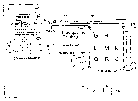
within the context of the electronic design.
[0011] In yet another embodiment, a computer-implemented method for
facilitating user customization of the image content of an image container in
an electronic
design, the method comprising downloading computer program code for
facilitating user
customization of the image content of an image container in an electronic
design to a user
computer for execution on the user computer, the code comprising code for
displaying an
electronic design to a user, the design comprising at least one image
container, the at least
one image container associated with a corresponding base image and displaying
a portion
6
CA 02705804 2014-09-24
of the base image therein; code for allowing the user to select an image
container from
the electronic design for customization; code for receiving a user selection
of an image
container from the electronic design; and code for displaying to the user,
simultaneously
with the electronic design, an image pane displaying the entire base image
associated
with the selected image container, thereby allowing the user to simultaneously
view both
the base image associated with the selected image container and the portion of
the base
image appearing in the electronic design within the context of the electronic
design.
[0011a] In yet another embodiment, a computer implemented method is
provided
for facilitating user customization of image content of an image container in
an electronic
design. The method comprising: downloading, by one or more processors,
computer
readable program instructions for facilitating user customization of the image
content of
the image container in an electronic design to a user computer for execution
on the user
computer, the computer readable program instructions including instructions
for
displaying in a customization window a cropped version of the image
corresponding to
an electronic design to a user, the design comprising at least one image
container, the at
least one image container associated with a corresponding base image and
displaying a
portion of the base image therein; allowing the user to select the image
container from the
electronic design for customization; displaying to the user, simultaneously
with the
electronic design, an image pane displaying the entire base image associated
with the
selected image container; providing at least one active control allowing to
modify the
image container in the electronic design and simultaneously updating the image
pane
with corresponding modifications to the appearance of the base image or the
portion
thereof as the modifications are made using the at least one active control,
thereby
allowing the user to simultaneously view both the base image associated with
the selected
image container and the portion of the base image appearing in the electronic
design
within the context of the electronic design.
[0012] In yet another embodiment, a system is provided for facilitating
user
customization of the image content of an image container in an electronic
design, the
system comprising one or more processors; and one or more computer readable
media
6a
CA 02705804 2014-09-24
having embodied therein computer code which, when executed by the one or more
processors, a method including downloading computer program code for
facilitating user
customization of the image content of an image container in an electronic
design to a user
computer for execution on the user computer, the code comprising code for
displaying an
electronic design to a user, the design comprising at least one image
container, the at least
one image container associated with a corresponding base image and displaying
a portion
of the base image therein; code for allowing the user to select an image
container from
the electronic design for customization; code for receiving a user selection
of an image
container from the electronic design; and code for displaying to the user,
simultaneously
with the electronic design, an image pane displaying the entire base image
associated
with the selected image container, thereby allowing the user to simultaneously
view both
the base image associated with the selected image container and the portion of
the base
image appearing in the electronic design within the context of the electronic
design.
6b
CA 02705804 2010-05-13
WO 2009/076279
PCT/US2008/085835
Brief Description of the Drawings
[0013] FIG. 1 is a block diagram of a computer system with which the
invention
may be employed;
[0014] FIGS. 2-16 are schematic representations of displays presented to a
user
engaged in designing an electronic document; and
[0015] FIG. 17 is a flowchart of an exemplary embodiment of a computer-
implemented method.
7
CA 02705804 2010-05-13
WO 2009/076279
PCT/US2008/085835
Detailed Description
[0016] Referring to FIG. 1, an exemplary user computer system UCS 100
includes processor 101 and memory 102. Memory 102 represents all UCS 100
components and subsystems that provide data storage, such as RAM, ROM, and
hard
drives. In addition to providing permanent storage for all programs installed
on UCS
100, memory 102 also provides temporary storage required by the operating
system and
the applications while they are executing. In a preferred embodiment, UCS 100
is a
typically equipped personal computer, but UCS 100 may also be a portable
computer, a
tablet computer or other device. The user views images from UCS 100 on display
140,
such as a CRT or LCD screen, and provides inputs to UCS 100 via input devices
150,
such as a keyboard and a mouse.
[0017] When UCS 100 is operating, an instance of the USC 100 operating
system
will be running, represented in FIG. 1 by operating system 103. In addition,
the user may
be running one or more application programs. In FIG. 1, UCS 100 is running Web
browser 105, such as Internet Explorer from Microsoft Corporation. Other
applications
that may be running in USC 100, such as spreadsheet, e-mail, and presentation
programs,
are represented as applications 104. In the depicted embodiment, design tools
106
include one or more product design programs downloaded to UCS 100 via network
120
from remote server 110, such as downloadable design tools provided by
VistaPrint
Limited and publicly available at vistaprint.com. Design tools 106 run in
browser 105
and allow the user to prepare a customized product design in electronic form.
Alternatively, design tools 106 may have been obtained by the user from memory
102 or
from another local source. Design tools 106 include an image editor tool 120,
which
provides the user with tools for scaling 121, placing 122, cropping 123, and
magnifying
124 images in an electronic product design. When the customer is satisfied
with the
design of the product, the design can be uploaded to server 110 for storage
and, if desired
by the user, subsequent production of the desired quantity of the physical
product on
appropriate printing and post-print processing systems. While server 110 is
shown in
8
CA 02705804 2014-03-12
FIG. 1 as a single block, it will be understood that server 110 may be
multiple servers
configured to communicate and operate cooperatively.
[0018] Memory 111 represents all components and subsystems that provide
server data storage, such as RAM, ROM, and disk drives or arrays. Template
memory
112 contains the various layout, design, color, font, and other information
provided by
the service provider to enable the creation and rendering of product design
templates. As
used in this embodiment, a template is an XML description of a product design
that
specifies the initial size, position and other attributes of all product
design elements such
as text containers, image containers, graphics, z-index values and so forth.
The site
operator may allow the user to modify one or more of the template elements.
[0019] Image memory 113 represents the portion of memory 111 that
contains the
images and any related image attributes used by the service provider to
generate the
product design, such as the image size, default colors associated with the
image, and one
or more keywords that have been associated with that image by the printing
service
provider. Image memory 113 includes a base image and may, but need not,
include one
or more cropped versions of the base image prepared by the service provider to
fit
various image container shapes. A wide variety of different templates can be
created by
combinations of layouts and images. U.S. Patent 7,133,050, assigned to the
assignee of
interest in the present application and entitled "Automated Image Resizing and
Cropping", discloses document editing systems for combining separately stored
images
and layouts to create document designs.
[0020] FIG. 2 is a simplified representation of an introductory product
selection
page 200 being viewed by the user of UCS 100 on user display 140. In this
example, the
page displays and promotes various products available from the service
provider and
offers active controls that allow the user of UCS 100 to select a desired type
of product
for a more detailed presentation of design options. By way of example, FIG. 2
shows
promotional images for business cards 210, postcards 220, stationery 230,
folded cards
9
CA 02705804 2013-12-09
r .
Docket Number 07-008 PCT
240, return address labels 250, and brochures 260. Images or promotions for
fewer,
different or additional products, such as presentation folders, invitations,
announcements,
thank you cards, gift tags, and so forth may also be presented along with
other
information and links. It will be understood that the invention is not limited
to
documents that are intended for eventual printing. The invention is also
applicable to the
design of documents intended for use in electronic form, such as electronic
business
cards, online brochures, and templates for presentation graphics software
programs. The
invention may as well be readily adapted to a wide range of products that a
user may
wish to customize, such as items of clothing, product containers, promotional
goods, and
so forth. It will also be understood that while the invention is described in
the context of
an embodiment of an electronic product design template, the image editing tool
may be
applied in the context of any type of electronic graphic design, for example
electronic
publishing tools, website design tools, etc.
[0021] As an illustrative example, it will be assumed that the user of
UCS 100
desires to create a personalized postcard and, therefore, selects the postcard
option, for
example by clicking with the user's mouse cursor on the postcard 220 image.
The user
will then be presented with one or more additional selection screens, not
shown, from
which the user can review the various postcard categories by general theme or
subject
matter and then, when the desired category is selected, review one or more
pages of
thumbnail images of postcard templates prepared by the service provider. When
a
desired template thumbnail is located, the user can click on the thumbnail
image to cause
server 110 to download the selected product design template information and
initiate a
custom product design session. As an alternative to providing a large gallery
of
thumbnail template images for the user to scan, the service provider may
provide a
keyword searching tool to allow the service provider to display only
thumbnails of
templates with images or other content corresponding to the user's search
terms.
[0022] Referring to FIG. 3, when the user selects a thumbnail image of a
specific
product design template that the user desires to customize, the user is
presented with a
customization window 300 which displays a larger customizable product design
template
CA 02705804 2013-12-09
Docket Number 07-008 PCT
301 of the selected product design. The selected product design template 301
may
contain a wide variety and number of images, colors, graphics and other design
components. For simplicity of discussion, in the example shown in FIG. 3,
product
design template 301 represents one side of a postcard being designed by a
user.
[0023] The selected product design template 301 may include text
containers 306,
308, 310, 312 which display text personalized by the user. Tools are provided
to allow
the user to customize the content of the text containers 306, 308, 310, 312.
In an
embodiment, the customization window 300 includes text prompts which prompt
the user
for personalized information for each of the text containers. In the example
template of
FIG. 3, the user is prompted for content related to "Headline" 316,
"Subheading" 318,
"Additional Information" 320, and "Call to Action or Phone Number" 322. When
the
user enters text for each prompt, the text is automatically displayed in the
corresponding
text containers 306, 308, 310, 312 in the product design template 301,
providing the user
with immediate feedback as to how the final product design will appear.
[0024] For ease of discussion, the product design template 301 is shown
as
having a single image container 302. It will be understood that template 301
could have
multiple image containers. As defined herein, an image container is an area in
an
electronic design that indicates the display boundaries of image content. When
a base
image associated with the image container 302 is uncropped, the image
container
dimensions match the base image dimensions. The product design template 301
may
automatically associate an image with the image container 302, for example as
pre-
associated by the template designer or as the result of a user keyword search,
and/or may
provide tools to allow the user to associate a user-provided image, or to
allow the user to
change the image associated with the container to any one of a number of
different
alternative images.
[0025] As mentioned above, the product design template 301 displayed to
the
user is the result of the combination of various separately stored template
component
elements including the text containers 306, 308, 310, 312, the image container
302, and
11
CA 02705804 2014-03-12
the layout describing the size and position of the containers. The initial
product design
template 301 is the starting point for the user's customized product design.
The user can
not only add the user's personalized text and additional images, but can also,
as discussed
below, modify the scaling, placement, sizing, magnification, and cropping of
images in
the product design template.
[0026] To allow the user to customize the product design template 301,
the user is
provided with template editing tools. Edit Tool Bar 330 contains various
buttons,
controls and menus allowing the user to add additional text boxes, insert
text, change the
font, change font attributes, and perform other typical editing actions. The
techniques
for designing and using edit tool bars are well known in the art. Navigation
buttons
Back 332 and Next 334 allow the user to move back to the previous display
screen or
ahead to the next. Different or additional navigation means may also, or may
alternatively, be employed.
[0027] Depending on the level of customization capabilities the service
provider
desires to give to the user, the service provider may also choose to provide
the user with
one or more additional instructions, tools, or controls (not shown) to
facilitate user
editing of the product design template 301, such as tools for changing the
template
layout, the color scheme, the design effects, or the font scheme. Co-owned
U.S. Patent
No. 7,322,007 entitled "Electronic Document Modification", issued January 22,
2008,
describes a document editing system and method using separately selectable
layouts,
designs, color schemes and font schemes.
[0028] Design tool 106 provides one or more methods to allow the user to
select
an image container for editing. In an embodiment, the user may select an image
container by single-clicking on the desired image in the product design
template, but it
will of course be understood that any of many other well-known techniques for
image
container selection may be used.
12
CA 02705804 2010-05-13
WO 2009/076279
PCT/US2008/085835
[0029] FIG. 4 illustrates the product design template 301 upon selection
of image
container 302, wherein selection of the image container is indicated by the
dashed line
bordering the perimeter of the image container 302. It will be understood that
many other
methods may be implemented for allowing the user to indicate selection of an
image
container, for example, by highlighting or otherwise providing a visual
distinction
between the selected image container 302 and the remaining non-selected
components of
the product design template 301.
[0030] Design tool 106 provides one or more methods to allow the user to
indicate a desire to modify an image in the product design template 301. For
example, as
illustrated in the pop-up instructions 341 in FIG. 5 which are displayed when
the cursor
303 is positioned over the image container 302, the design tools 106 may
require the user
to position the cursor 303 over the desired image container, right-click to
display a pull-
down action list, and click on an edit option. In another example, as
illustrated in FIG. 6,
the design tools may require the user to click on a link such as an Advanced
Editing
button 340. It will be understood that many other methods may be implemented
for
allowing the user to indicate a desire to modify an image container, for
example, by
positioning the user's mouse cursor over the desired image container and
double clicking
the image, or by displaying an editing tool automatically upon selection of an
image
container.
[0031] Referring to FIG. 7, in response to the user's action of
indicating a desire
to modify a selected image container, for example using one of the methods
illustrated in
FIGS. 5 or 6, a panel referred to herein as an image editor tool 400 is
presented to the
user simultaneously with the product design template 301 in the customization
window
300. Image editor tool 400 includes an image pane 410 which displays a
thumbnail
image of the base image 411 that is currently associated with the selected
image container
302. If the base image 411 has the same aspect ratio as image pane 410, it
will
completely fill the image pane 410 when displayed. More likely, however, the
base
image 411 will not have the same aspect ratio as the image pane 410 and
therefore, in
order to display the thumbnail, the thumbnail image of the base image 411 will
be scaled
13
CA 02705804 2010-05-13
WO 2009/076279
PCT/US2008/085835
to fit (i.e., maintaining the aspect ratio of the base image) within the image
pane 410.
Portions 413 of the image pane 410 not filled with the thumbnail image of the
base image
411 are filled with transparent overlays.
[0032] During the design of the product design template 301, the template
designer may have previously cropped the base image 411 to select only a
portion of the
image 411 to be displayed in the image container 302. For example, in the
embodiment
shown, the base image 411 has been previously cropped by the template designer
to the
portion of the base image within the dashed lines indicated at 414 so that
only the
cropped portion of the base image 411 appears in the product design template
301.
[0033] When an image is not previously cropped upon activation of the
image
editor tool 400, the dimensions of the base image 411 are proportional to the
dimensions
of the selected image container 302, and the image content of the image
container 302
corresponds to the full base image 411.
[0034] The image editor tool 400 offers the user the editing choices of
modifying
the current placement of the selected image container 302, modifying the
current scale
(i.e., size) of the selected image container 302, modifying the portion of the
base image
411 displayed in the selected image container 302, and modifying the
magnification of
the image content displayed in the selected image container 302. While it will
be
appreciated that there are many ways to implement the activation of these
various editing
choices (i.e., indicating the user's desire to perform one of these
operations), in the
illustrative embodiment, the image editor tool 400 has two modes: a Place and
Scale
mode in which the user may utilize a Place tool 351 and a Scale tool 352, as
will be
discussed below in connection with FIGS. 10-16, and a Crop and Magnify mode in
which
the user may utilized a Crop tool 353 and a Magnify tool 354, as will also be
discussed
below in connection with FIGS. 10-16. In the illustrative embodiment, the
Place and
Scale mode is activated by selecting a link in the image editor tool 400 in
the form of a
button 421. The Crop and Magnify mode is activated by selecting a link in the
image
editor tool 400 in the form of a button 422. Each of these modes will be
discussed in
14
CA 02705804 2010-05-13
WO 2009/076279
PCT/US2008/085835
more detail below. The user may also, if desired, choose to cancel the image
editor tool
400 by deselecting the image container 302, for example by clicking elsewhere
in the
product design image.
[0035] Upon initial activation of the image editor tool 400, in one
embodiment
(shown in FIG. 7), the Place and Scale mode is automatically active, i.e.,
available to the
user. Of course, in other embodiments, the Crop and Magnify mode may be
initially
automatically active, or other combinations, or only one, of the tools (Place,
Scale, Crop,
Magnify) may be automatically active. Alternatively, other embodiments may
dictate
that none of the tools are automatically active until the user actively
selects a particular
operation.
[0036] Turning now to the discussion of the Scale tool 352 in FIG. 7, the
Scale
tool 352 is an active control provided and displayed as drag handles 305
(shown as 305a,
305b, 305e, 305d) on the selected image container 302 in the product design
template
301. In the illustrative embodiment, the drag handles 305, indicated by small
square
boxes, are located on the corners of the selected image container 302. If a
user clicks on
one of the drag handles 305 and moves the mouse to drag the cursor 303, the
image
container 302 changes size while maintaining the aspect ratio of the original
container.
As is well known, the aspect ratio of an image is the ratio of the image's
width to the
image's height. The aspect ratio of the image container is the ratio of the
container's
width to height. Thus, if the mouse is moved to drag the cursor 303 in a
direction
towards the interior of the image container 302, the image container 302
becomes
proportionally smaller wherein the dimensions of the image container 302
maintain the
same aspect ratio as the dimensions of the originally sized image container
302 (i.e., the
ratio of the height to width of the image container 302 is constant even as
the actual
dimensions of the image container 302 are changed). Conversely, if the mouse
is moved
to drag the cursor 303 in a direction away from the interior of the image
container 302,
the image container 302 becomes proportionally larger wherein the dimensions
of the
image container 302 maintain the same aspect ratio as the dimensions of the
originally
sized image container 302.
CA 02705804 2010-05-13
WO 2009/076279
PCT/US2008/085835
[0037] Importantly, the image content of the image container 302
maintains the
same aspect ratio as the image content of the originally sized image container
302 as
well. Thus, if the image container 302 becomes larger, the displayed image
container
302 is the same content as the original image container 302 but is scaled
proportionally
larger such that it fills the larger image container 302. It will be noted
that because the
base image comprises only a fixed number of pixels, when the image container
is scaled
to a larger size in the Place and Scale mode, the resolution of the displayed
image content
will decrease. The opposite is true when the image container 302 is scaled to
a smaller
size, although the resolution of the displayed image content has an upper
bound limited to
the resolution of the user's display screen and associated graphic settings of
the user's
monitor. When a product design template is printed, however, the resolution
has an
upper bound of the resolution of the base image.
[0038] Referring now to FIG. 8, in this example the user has clicked on
drag
handle 305a and has moved the mouse to drag the cursor 303 in a direction
toward the
interior of the image container 302. Upon release of the mouse click, the size
of the
image container 302 is fixed to that indicated by 302a. Thus, the image
container 302
and associated image content has been resealed to a smaller proportional size,
as
indicated by 302a. Note that the aspect ratio of both the container dimensions
and the
image content is maintained. Thus, the ratio of height to width of image
container 302 is
the same as the ratio of height to width for modified image container 302a.
Note also that
while the drag handles 305 are implemented and displayed in the illustrative
embodiment
on the corners of the image container 302, in alternative embodiments they may
be
alternatively or additionally implemented and displayed along any point of the
perimeter
of the image container 302. For example, while not shown, drag handles may be
implemented and displayed on the midpoints of each image container boundary
section
between every set of two adjacent corners. Thus, if a user drags on a handle
305 that is
connected to only one boundary (e.g., only one of a horizontal or vertical
boundary of
image container 302), the Scale tool 352 automatically adjusts the adjacent
boundaries
(e.g., the vertical boundaries if the selected handle is connected to a
horizontal boundary,
16
CA 02705804 2010-05-13
WO 2009/076279
PCT/US2008/085835
and the horizontal boundaries if the selected handle is connected to a
vertical boundary)
to maintain a constant aspect ratio.
[0039] It will be appreciated that in scaling an image container 302 and
its
associated image content, one point of the image container 302 must be fixed,
or
"anchored", from which to allow relative expansion or compression of all of
the other
points in the image container 302 (and associated image content). In the
illustrative
embodiment, the anchor point is chosen as the opposite corner of the selected
drag handle
305. However, it will be appreciated that in practice, any point of the image
container
(either along the perimeter or within the interior) may serve as an anchor
point and it is
up to the image editor tool designer to select and implement the anchor
protocol and/or to
allow the user to choose an anchor point. For purposes of simplicity of
description of the
present invention, the anchor points of the image containers in the
embodiments
described herein are selected to be the corner of the image container 302
located opposite
from the selected drag handle.
[0040] In the example shown in FIG. 8, the image container 302 is scaled
to a
smaller size (shown as 302a). Note that because the scaling operation does not
alter the
base image, the thumbnail image of the base image displayed in the image pane
410
remains unchanged after a scale operation. To scale the image container 302 to
a larger
size, a similar technique is performed but the handle is dragged away from the
interior of
the image container 302. More specifically, the user selects one of the drag
handles 305a,
305b, 305c, 305d by clicking on the mouse and moves the cursor 303 in a
direction away
from the interior of the image container 302 until it is a desired size, and
then releases the
mouse click to fix the size of the image container 302 to that of the desired
size. Similar
scaling operations may be performed with selection of any one of the drag
handles 305
accompanied by a standard drag-and-drop action.
[0041] Turning now to discussion of the Place tool 351, the Place tool
351 allows
the user to modify the placement of the selected image container 302 in the
product
design template. Referring to FIG. 9, The Place tool 351 is an active control
wherein the
17
CA 02705804 2010-05-13
WO 2009/076279
PCT/US2008/085835
placement of an image container 302 (shown as resealed image container 302a)
may be
modified by single clicking within the interior of the selected image
container, moving
the mouse to drag the container to a desired alternative location, and
releasing the mouse
click. For example, as illustrated in FIG. 9, the image container 302 has been
moved
from an original location, shown as 302a, to a different location, shown as
302b. Note
that because the placement operation does not alter the base image, the
thumbnail image
of the base image displayed in the image pane 410 also remains unchanged after
a
placement operation.
[0042] In an embodiment, an image container 302 may be moved to any
location
within the boundaries of the product design template 301. In an alternative
embodiment,
an image container may be moved to any location within or partially outside
the
boundaries of the product design template 301; however, image content of any
portion of
an image container that is outside the boundaries of the product design
template 301 will
not appear in the actual product when the product design is finalized (e.g.,
printed or
published).
[0043] Turning now to discussion of the Crop and Magnify mode of the
image
editor tool 400, FIG. 10 illustrates the image editor tool 400 upon selection
of the button
422. As shown, upon selection by the user of the Crop and Magnify tool button
432, the
image editor tool 400 again includes the image pane 410 which displays the
base image
411 currently associated with the selected image container 302 and a cropping
window
412 overlaying the image pane 410. The boundaries of the cropping window 412
define
the portion of the base image 411 that is displayed in the selected image
container 302 in
the product design template 301. As discussed previously, the designer of the
product
design template 301 may have pre-cropped the base image 411, in which case the
cropping window 412 will circumscribe only a portion of the base image, as
illustrated in
FIG. 10. Alternatively, the entire base image may be used in the template, in
which case
the cropping window 412 will circumscribe the entire base image. The image
editor tool
400 also includes a Magnify tool 354, discussed in more detail hereafter,
which allows
18
CA 02705804 2010-05-13
WO 2009/076279
PCT/US2008/085835
the user to modify the magnification level of the image content in the
selected image
container 302.
[0044] Turning the discussion now to the Crop tool 353, the Crop tool 353
includes active controls which allows the user to reshape the dimensions of
the cropping
window 412 in either the image pane 410 or the product design template 301.
The effects
on the size of the image container 302 in the product design template 301 due
to changes
made to the cropping window 412 using the Crop tool's active control in the
image pane
410 are automatically visible to the user. Conversely, the effects on the size
of the
cropping window 412 in the image pane 410 due to changes made to the image
container
302 in the product design template 301 using the Crop tool's active control
are
automatically visible to the user.
[0045] In an embodiment, the Crop tool's active control in the product
design
template 301 comprises drag handles 315, shown as 315a, 315b, 315c, 315d,
315e, 315f,
315g, 315h connected to each of the boundaries of the image container 302. In
the
illustrative embodiment, drag handles 305, indicated by small circles, are
positioned on
the corners and midpoints of the boundary sections of the image container 302.
It will be
appreciated that the number and positions of the drag handles 315 may differ
from the
number and positions illustrated.
[0046] The Crop tool drag handles 315 allow a user to modify the shape
and size
of the image container 302 and to thereby automatically change the
corresponding shape
and size of the cropping window 412 displayed in the image pane. The drag
handles 315
are provided to allow the user to drag-and-drop the boundaries of the selected
image
container 302 displayed in the product design template 301 (resulting in
corresponding
modification of the shape and size of the cropping window 412 displayed in the
image
pane 410). Drag handles connected to only one boundary section (for example,
drag
handles 315e, 315f, 315g, 315h connected to the midpoints of the selected
image
container 302) can only be used to drag-and-drop the boundary to which they
are
connected. Drag handles connected to two different boundary sections (for
example,
19
CA 02705804 2010-05-13
WO 2009/076279
PCT/US2008/085835
drag handles 315a, 315b, 315e, 315d connected to the corners of the selected
image
container 302) simultaneously drag-and-drop both connected boundaries.
[0947J In the Crop tool 353, when a boundary section is moved to modify
the size
and shape of an image container 302, the image content displayed in the image
container
302 is correspondingly updated to display the portion of the base image 411
that is
bounded by the newly sized and shaped cropping window 412 as shown in the
image
pane 410. In an embodiment, while not shown, the base image 411 may be
displayed in
shaded versions of the image tones used to render the portion 413 of the base
image 411
circumscribed by the cropping window 412 in order to provide a more visually
distinct
indication of which portion 413 of the base image 411 corresponds to the image
content
displayed in the selected image container 302 of the product design template
301.
Importantly, changes to the size and shape of the cropping window 412 using
the Crop
tool do not result in any changes to the image content of the image container
302 in terms
of either scaling or magnification.
[0048] Turning now to an example application of the Crop tool, FIG. 11A
shows
the product design screen after the user has selected the drag handle 315e
positioned at
the midpoint of the top horizontal boundary section of the selected image
container 302
(shown as 302b), and dragged the handle 315e via the mouse to the position
shown,
resulting in the image container 302 having size and shape as shown (indicated
as 302c).
As illustrated, the top portion of the image content displayed in container
302b is cropped
off in the resulting image container 302c, yet the scaling and magnification
of the image
content remains the same. Note also that the cropping window 412 in the image
pane
410 is updated to reflect the change in dimensions of the image container 302,
and
maintains the same aspect ratio as the modified image container 302c. The
portion of the
base image 411 captured by the updated cropping window 412 corresponds to the
image
content displayed in the modified image container 302e.
[0049] Continuing with this example, FIG. 11B shows the product design
screen
after the user has selected the drag handle 315g positioned at the midpoint of
the bottom
CA 02705804 2010-05-13
WO 2009/076279
PCT/US2008/085835
horizontal boundary section of the selected image container 302 (shown as
302c), and
dragged the handle 315g via the mouse to the position shown, resulting in the
image
container 302 having size and shape as shown (indicated as 302d). As
illustrated, the
bottom portion of the image content displayed in container 302c is cropped off
in the
resulting image container 302d, yet again the scaling and magnification of the
image
content remains the same. Again, the cropping window 412 in the image pane 410
is
updated to reflect the change in dimensions of the image container 302, and
maintains the
same aspect ratio as the modified image container 302d. The portion of the
base image
411 captured by the updated cropping window 412 corresponds to the image
content
displayed in the modified image container 302d.
[00501 In FIG. 11C, the image is further cropped, this time by dragging
the
handle 315f on the right vertical boundary section of image container 302d to
the left,
resulting in the image container 302 having size and shape as shown (indicated
as 302e).
Again, the scaling and magnification of the image content remains the same
even as the
right portion of the image content displayed in container 302e is cropped off.
Again, the
cropping window 412 in the image pane 410 is updated to reflect the change in
dimensions of the image container 302, and maintains the same aspect ratio as
the
modified image container 302e. The portion of the base image 411 captured by
the
updated cropping window 412 corresponds to the image content displayed in the
modified image container 302e.
100511 The handle 315h on the left vertical boundary section of image
container
302 operates similarly and may be dragged to the right or to the left to move
the left
vertical boundary section to the right or left, as desired. It is to be
understood that the
vertical boundary sections may be moved right or left using the handles
connected
thereto, and the horizontal boundaries may be moved up or down using the
handles
connected thereto. The remaining corner handles 3I5a, 315b, 315e, 315d each
connect to
both a horizontal drag handle and a vertical drag handle. When these handles
are selected
and dragged, the connected horizontal and vertical boundary sections are
simultaneously
moved out or in.
21
CA 02705804 2010-05-13
WO 2009/076279
PCT/US2008/085835
[0052] The Crop tool 353 also includes an active control in the image
pane 410 to
allow the user to modify the position and dimensions of the cropping window
412 from
the image pane 410. In this regard, the active control may include a cropping
window
placement control, for example activated by clicking within the cropping
window 412 in
the image pane 410 to select the cropping window and then operating according
to a
standard drag-and-drop operation to allow the user to pick and move the
position of the
cropping window 412 over the base image 411 displayed in the image pane 410.
For
example, FIG. 12 illustrates the position of the cropping window 412 (show as
412a)
after the user has performed a drag-and-drop operation on the cropping window
412 from
its position as shown in FIG. 11C.
[0053] Although not shown, the Crop tool active controls in the image
pane 410
may also include drag handles connected to the cropping window 412 in the
image pane
410 which allow a user to drag-and-drop boundaries of the cropping window 412
to
modify the size and shape of the cropping window 412 from the image pane 410.
This
operation would operate similarly to Crop tool's active control in the product
design
template 301, but would be active in the image pane 410 and associated with
the cropping
window 412 rather than the image container 302.
[0054] In an embodiment, when the cropping window 412 is repositioned in
a
drag-and-drop operation using the active placement control in the image pane
410, the
boundaries of the cropping window 412 are limited to the outer boundaries of
the base
image 411. Thus, if the cropping window 412 is dragged such that one of its
edges
reaches the outer boundary of the underlying base image 411, it cannot be
dragged past
that edge.
[0055] In an embodiment, when the cropping window 412 is reshaped using
the
active control on the image container 302 in the product design template 301
(by
selecting a boundary on the image container 302 and performing a drag-and-drop
operation such that an edge of the resulting modified cropping window reaches
an edge
22
CA 02705804 2013-12-09
Docket Number 07-008 PCT
of the base image 411 in the image pane 410), the edge of the cropping window
is limited
to the edge of the base image 411 and the corresponding selected boundary of
the image
container 302 cannot be expanded further. If more than one boundary is
selected and
dragged simultaneously, when a first boundary of the corresponding cropping
window
412 reaches an edge of the base image 411 in the image pane 410, the crop tool
353 may
limit the first boundary of the cropping window 412 to that edge but allow
further
expansion on the remaining boundaries as long as and until the remaining
boundary
reaches another edge of the base image 411. As an example, FIG. 13 illustrates
the
expansion of the cropping window (from 412a to 412c) through the selection of
a corner
handle control 315b on the image container 302 when image editor tool 400 is
in the
Crop and Magnify mode. As illustrated, as the image container 302 is expanded
outward,
the resulting cropping window 412a in the image pane 410 approaches the left
edge of
the base image 411. When the resulting cropping window 412 reaches the left
edge
(indicated at 412b when the image container is as indicated at 3020 and the
cursor
movement continues to drag outward, the cropping window 412 hugs the left edge
of the
base image 411 (indicated at 412c when the image container is as indicated at
302g) yet
allows the top horizontal boundary to continue to expand upward until it
reaches the top
edge of the base image 411, where further upward expansion prevented.
[0056] FIG. 14A illustrates the customization window 300 upon selection
by the
user of the Magnify tool 354 in the image editor tool 400. In the embodiment
shown, the
Magnify tool 354 is implemented as a slider 431 which may be dragged to any
position
along a slide 432 to change the magnification of the image content in the
cropping
window 412 and simultaneously in the selected image container 302 displayed in
the
product design template 301. The location of the slider 431 along the slide
432 indicates
and determines the degree of magnification of the image content in the
selected image
container 302. In an embodiment, the range of magnification ranges from full
negative
cropping to a maximum magnification of 100 dots per inch (DPI).
[0057] FIG. 14A illustrates full negative cropping, wherein the slider
431 is on
the far left end of the slide 432. Full negative cropping occurs when the base
image 411
23
CA 02705804 2010-05-13
WO 2009/076279
PCT/US2008/085835
is scaled to fit the image container 302 and thus, unless the dimensions of
the base image
411 have the same aspect ratio as the dimensions of the image container 302,
the portions
of the image container 302 not filled by the image 411 are filled with
transparent overlays
313. Of course, the image container 302 (indicated as 302h) most likely will
not have the
same aspect ratio as the image pane 410 so the transparent overlays 313 would
not have
the same aspect ratio as the transparent overlays 413 displayed in the image
pane 410.
[0058] FIG. 14B illustrates some magnification, wherein the slider 431 is
positioned between the far left and far right points of the slide 432, and
FIG. 14C
illustrates maximum magnification, wherein the slider 431 is positioned on the
far right
end of the slide 432. It will be appreciated that the range of available
magnification is a
function of the pixel density of the image 411.
[00591 FIG. 14B shows that the slider 431 has been dragged from its
original
location on the far left end of the slide 432 (indicated at 434a) which
corresponds to full
negative cropping (i.e., "scale to fit the image container") as illustrated in
FIG. 14A, to
the location indicated at 434b. When the slider 431 is dragged along the slide
432, the
Magnify tool 354 responds by automatically resizing the cropping window 412 in
the
image pane 410 to a smaller size (preferably proportional to the position of
the slider 431
along the slide 432) while maintaining the center point of the image content
in the image
container 302 and maintaining the aspect ratio of the cropping window 412 and
corresponding image container 302. Since the image container 302 itself does
not change
in size or dimension during utilization of the Magnify tool 354, the image
content
captured within the boundaries of the cropping window 412 is automatically
resealed and
displayed in the selected image container 302 while maintaining the aspect
ratio of the
cropping window 412 and image container 302. These actions are performed
automatically by the image editing tool 400 upon detection of user input
indicating a
change in magnification. That is, upon detection of a user's desire to change
the
magnification (by way of a detection of a drag operation on the slider 431 by
the user),
the system automatically determines the degree of magnification corresponding
to the
updated position of the slider 431, determines the corresponding resolution
required to
24
CA 02705804 2010-05-13
WO 2009/076279
PCT/US2008/085835
achieve the degree of magnification, determines the dimensions of the cropping
window
412 corresponding to the determined resolution as required to maintain the
aspect ratio of
the cropping window 412 and image container 302, displays the cropping window
412
according to the determined dimensions, and displays the image content
captured by the
adjusted cropping window 412 in the image container 302 at the selected
resolution. A
typical embodiment of the Magnify tool 354, written in Java script, appears
in
Appendix A.
[00601 Thus, in FIG. 14B, the desired change in magnification resulting
from the
dragging of the slider 431 from position 434a to position 434b results in
automatic
resizing of the cropping window 412 to the correspondingly smaller size, as
illustrated.
Note that the current resolution in this example is displayed as having
decreased from the
original 2000 DPI down to 612 DPI after the change in magnification. Note also
that in
magnifying a small portion of the image in this way, a smaller detail of the
base image
411 may be enlarged to become more visible to the user. For example, in FIG.
14B, the
image content of the selected image container 302g (shown as 302f in FIG. 14A)
is
magnified to reveal more detail that may have not been visible to the user at
the previous
magnification level.
[0061} FIG. 14C illustrates the image container 302 (shown as 302k) when
the
slider is moved as far to right as allowed (indicated at position 434c on the
slide 432) to
further increase the magnification of the image content of the selected image
container
302g. In this example, the additional magnification seen in container 302g may
reveal
further detail in the selected portion of the base image 411.
[0062] FIG. 14D illustrates changes in the cropping window 412 resulting
from a
change in position of the slider 431 along the slide 432 from a higher
magnification level
to a lower magnification level. In this example, the cropping window 412
begins with an
initial size (indicated as 412a) and expands while maintaining its aspect
ratio until one of
the boundaries of the cropping window 412 reaches a boundary of the base image
411
(for example, the right boundary of the cropping window indicated at 412b).
Once this
CA 02705804 2010-05-13
WO 2009/076279
PCT/US2008/085835
happens, the cropping window 412 continues to expand as the magnification
decreases
(as a result of the slider 431 moving to the left) but the boundaries of the
cropping
window 412 are not allowed to expand past the corresponding boundaries of the
base
image 411. Thus, as the slider 431 is further moved to the left, the right
boundary of the
cropping window 412 remains at the right boundary of the image, but the
remaining
boundaries are allowed to continue to expand. As the bottom boundary reaches
the
bottom boundary of the base image, indicated at 412e, the bottom boundary of
the
cropping window 412 remains at the bottom boundary of the base image 411 while
the
remaining left and top boundaries of the cropping window continue to expand,
indicated
at 412d. The edge limitation feature of the Crop tool 353 has the additional
advantage of
providing seamless integration between positive and negative cropping. A
typical
embodiment of this seamless cropping tool 354, written in Java script,
appears in
Appendix C.
[0063] It will be appreciated by those skilled in digital imaging
techniques that
the magnification technique provided by the Magnify tool 354 must be balanced
against
the decrease in resolution which results from the magnification. That is,
because the base
image 411 is made of a discrete number of pixels, when the cropping window 412
is
made smaller to select a smaller number of the overall limited number of
pixels of the
base image 411, these smaller number of selected pixels are scaled to fit
within the
dimensions of the unchanged image container 302 to make the content of the
selected
pixels more visible to the user. However, because there are fewer actual
pixels selected,
the actual image content is decreased as the magnification is increased.
[0064] For this reason, the image editor tool 400 may include a Resolution
indicator 450 which monitors the current resolution of the selected image
container 302
and may generate a warning to the user if the current resolution dips below a
predetermined minimum threshold. This may be important to a user whose product
design is to be used in applications that require the image content to be of a
certain
minimum resolution, or which simply look better when the image content to be
of a
certain minimum resolution. For example, if the finalized product is to be
printed, it is
26
CA 02705804 2010-05-13
WO 2009/076279
PCT/US2008/085835
generally thought that printed material looks better with a minimum resolution
of
approximately 300 DPI. Therefore, in an embodiment, the Resolution indicator
450 may
generate a warning at 75% of the lowest desired DPI (i.e., at 225 DPI).
Certain printers
may not allow resolutions below this level, and therefore, if the user is
provided with an
indicator that the current resolution is below a given threshold, the user is
then provided
with the opportunity to increase the magnification to prevent this problem in
the final
product.
[0065] In both the Crop tool 353 and the Magnify tool 354, the image
editor tool
400 may provide the user with the additional flexibility of allowing
adjustment of the
placement of the cropping window 412 over the underlying base image 411
without
changing the placement or size and dimensions of the image container. In an
embodiment, illustrated in FIGS. 15A and 15B, the image editor tool 400 allows
the user
to click on the image content within the selected image container 302 in the
product
design template 301, and then drag the cursor 303 in the desired direction to
pull the
image content in the direction of the cursor. Thus, in FIG. 15A, the user
clicks on the
image content in image container 302 and drags the cursor 303 from a position
303a to a
position 303b, as indicated in FIG. 15A, resulting in the adjustment of the
image content
to that shown in FIG. 15B. In this operation, it appears to the user as if the
user is
essentially "sliding" the underlying base image 411 around underneath the
image
container 302 until the desired portion of the image appears in the image
container 302.
However, in implementation, the Crop tool 353 responds to the user's cursor
movements
within the boundaries of the image container 302 to adjust the position of the
cropping
window 412 over the base image 411 in the image pane 410 of the image editor
tool 400.
Thus, the user can simultaneously see the changes in the position of the
cropping window
412 when dragging the image content in the image container 302 to adjust the
placement
of the image in the image container 302. A typical embodiment of this cropping
window
placement tool, written in Java script, appears in Appendix C.
[0066] To achieve the same result, illustrated in FIG. 16, the user may
alternatively select the cropping window 412 in the image pane 410 and drag-
and-drop it
27
CA 02705804 2010-05-13
WO 2009/076279
PCT/US2008/085835
as desired to place the cropping window 412 over the desired image content.
Thus, as
shown in FIG. 16, the user has selected the cropping window 412 (indicated as
4120 and
dragged to another position (indicated as 412g), and the content of the image
container
302 is correspondingly updated.
[0067] In
either of the operations shown in FIGS. 15A/15B and 16, the results are
updated in both the product design template 301 and the image pane 410
simultaneously.
It will further be appreciated that while performing a drag-and-drop of the
image content
within the image container 302 of FIGS, 15A/15B and performing a drag-and-drop
of the
cropping window 412 over the base image 411 in the image pane 410 of FIG, 16
yield
identical results, each offers a different advantage to the user. The
operation illustrated in
FIGS. 15A/15B offers the user image placement adjustment from the product
design
context, whereas the operation illustrated in FIG. 16 offers the user the same
adjustment
from the image context.
[0068] FIG. 17
illustrates an embodiment of a computer-implemented method for
facilitating user customization of the image content of an image container in
an electronic
design. In performing the method, a computer executes program code which is
embodied
on one or more computer readable media and which instructs the computer to
perform the
various steps of the method 500. Turning now to the steps of the method, a
computer
performs the steps of displaying an electronic design having at least one
image container
on a screen of a user's computer wherein the at least one image container has
associated
with it a corresponding base image (step 502), determining a portion of the
base image to
be displayed in the image container (step 504), displaying the identified
portion of the
base image in the image container(step 506), receiving user selection of an
image
container from the electronic design for customization (step 508), and
displaying to the
user, simultaneously with the electronic design, an image pane displaying the
entire base
image associated with the selected image container (step 510), thereby
allowing the user
to simultaneously view both the base image associated with the selected image
container
and the portion of the base image appearing in the electronic design within
the context of
the electronic design.
28
CA 02705804 2013-12-09
, .
Docket Number 07-008 PCT
[0069] The computer may perform the further steps of displaying a
cropping
window circumscribing the portion of the base image that is displayed in the
selected
image container (step 512), displaying at least one active control which
allows
modification of how the base image, or portion thereof, appears in the
electronic design
(step 514), receiving user modification via the at least one active control
(step 516), and
simultaneously updating the display of both the product design and the
cropping window
with modifications to the appearance of the base image or the portion thereof
as the
modifications are made using the at least one active control (step 518),
preferably
limiting the position and boundaries of the cropping window to within the
boundaries of
the base image (step 520).
[0070] The scope of the claims should not be limited by the preferred
embodiments set forth in the examples, but should be given the broadest
interpretation
consistent with the description as a whole.
29
CA 02705804 2010-05-13
WO 2009/076279
PCT/US2008/085835
Appendix A
// Magnifying while keeping the center point //
// get zoom percent from new slider value (width)
var zoomPercentDelta = (newWidth / my.zoomStartRect.width) - 1;
// new size + position
var mainImage {};
// calculate new sizes
// -> add side deltas to dimensions
mainImage.width = my.zoomStartRect.width + zoomPercentDelta *
my.zoomStartRect.width;
mainImage.height = my.zoomStartRect.height + zoomPercentDelta *
my.zoomStartRect.height;
// calculate new position
// -> preserve center point of image!
var mainCropArea vp.ui.getLocalRect(my.mainCropArea); // container
// center % = where is the container's center point on the whole image
// ¨ image distance to container center / total image size
// = (crop area size /2 - image offset) / total image size
var heightCenterPercent = ((mainCropArea.height /2) - my.zoomStartRect.top) /
my.zoomStartRect.height;
var widthCenterPercent = ((mainCropArea.width / 2) - my.zoomStartRectleft) /
my.zoomStartRect.width;
// calculate new position, keeping center %s constant
mainImage.top = (mainCropArealeight / 2) - (mainImage.height *
heightCenterPercent);
mainImageleft = (mainCropArea.width /2) - (mainImage.width *
widthCenterPercent);
CA 02705804 2010-05-13
WO 2009/076279
PCT/US2008/085835
Appendix B
// Magnifying while hugging edges (for smooth transition to negative cropping)
//
var mainArea = vp.ui.getLocalRect(my.mainCropArea); II image container (is the
crop area)
var mainImage = vp.ui.getLocalRect(my.mainCropImage); // full image (is
bounding box for crop area)
// bounds checks vertical
if (mainImage.top > 0)
{
mainImage.top ¨ 0;
}
else if (mainImage.bottom < mainArea.height)
{
mainImage.top = mainArea.height - mainImage.height;
}
// bounds checks horizontal
if (mainImage.left > 0)
{
mainImageleft ¨ 0;
}
else if (mainImage.right < mainAreamidth)
{
mainImage.left = mainArea.width - mainImage.width;
}
// negative-cropping centering
// maintain invariant:
// if negatively cropped in a dimension, then:
// - image is centered in that dimension
// - other dimension never has white space on a side
if (mainImage.width < mainAreamidth)
f
mainlmageleft = (mainArea.width - mainImage.width) /2;
1
if (mainimage.height < mainArea.height)
{
mainImage.top = (mainArea.height - mainImage.height) /2;
}
31
CA 02705804 2010-05-13
WO 2009/076279
PCT/US2008/085835
Appendix C
II Adjusting the crop container's bounding box to be the actual, possibly
hidden
position of the image //
// find current image + container
var mainArea = vp.ui.getLocalRect(my.mainCropArea); II image container (is the
crop area)
var mainImage = vp.ui.getLocalRect(my.mainCropImage); // full image (is
bounding box for crop area)
// make image coordinates absolute with container
mainImage.top = mainImage.top + mainArea,top;
mainImage.left = mainlmageleft + mainArealeft;
// deal with negative cropping
II invariant: if negatively cropped in a dimension, then image is centered in
that
dimension
if (mainImage.width < mainArea.width)
// restrict resizing - this is the max zoom
mainImage.left = mainAreadeft;
mainImage.width = mainArea.width;
if (mainlmage.height < mainArea.height)
// restrict resizing - this is the max zoom
mainImage.top mainArea.top;
mainImage.height = mainArea.height;
my,mainCropManipulator.setBoundingBox(mainImage);
32