Language selection

Search

Patent 2706298 Summary

Third-party information liability

Some of the information on this Web page has been provided by external sources. The Government of Canada is not responsible for the accuracy, reliability or currency of the information supplied by external sources. Users wishing to rely upon this information should consult directly with the source of the information. Content provided by external sources is not subject to official languages, privacy and accessibility requirements.

Claims and Abstract availability

Any discrepancies in the text and image of the Claims and Abstract are due to differing posting times. Text of the Claims and Abstract are posted:

  • At the time the application is open to public inspection;
  • At the time of issue of the patent (grant).
(12) Patent Application: (11) CA 2706298
(54) English Title: IMPROVED VEHICLE SEAT
(54) French Title: SIEGE DE VEHICULE AMELIORE
Status: Deemed Abandoned and Beyond the Period of Reinstatement - Pending Response to Notice of Disregarded Communication
Bibliographic Data
(51) International Patent Classification (IPC):
  • B60N 2/42 (2006.01)
  • A47C 3/20 (2006.01)
  • F16F 7/00 (2006.01)
  • F41H 7/00 (2006.01)
(72) Inventors :
  • GRANT, NEIL (Canada)
(73) Owners :
  • MED-ENG, LLC
(71) Applicants :
  • MED-ENG, LLC (United States of America)
(74) Agent: GOWLING WLG (CANADA) LLP
(74) Associate agent:
(45) Issued:
(22) Filed Date: 2010-06-01
(41) Open to Public Inspection: 2011-12-01
Availability of licence: N/A
Dedicated to the Public: N/A
(25) Language of filing: English

Patent Cooperation Treaty (PCT): No

(30) Application Priority Data: None

Abstracts

English Abstract


This invention relates to a system and method of armed forces vehicle seating
which
reduces the potential for injury to occupants when the vehicle is subjected to
a landmine
or similar explosive device. The seats are floor, ceiling or wall mounted and
include a
trailer arm which allows deflection while providing stability. This
arrangement isolates
the occupants from the chassis of the vehicle via a pneumatic or other shock
absorber.
These seats can also be combined with shock absorbing/isolating foot rests,
appendage
(leg) restrain systems and an occupant four-point harness to offer a
completely
integrated system. This integrated system reduces acceleration/deceleration
related
injuries, shock injuries to the lower legs, flailing injuries to the lower
legs and internal
collision injuries. Other options and alternatives are also described.


Claims

Note: Claims are shown in the official language in which they were submitted.

WHAT IS CLAIMED IS:
1. A vehicle seat comprising:
a first vertically disposed tube;
a second vertically disposed tube slidably engaged within said first tube in
telescopic
relationship;
a base, mounted to said first tube, for bracing to a vehicle seat;
a second base, mounted to said second tube for mounting to a vehicle;
a shock absorber disposed within said first and second tubes, one end of said
shock
absorber being fixed to said first tube and the other end of said shock
absorber
being fixed to said second tube; and
a trailing arm pivotally connected between said seat and said vehicle,
providing stability.
2. A shock absorbing seat comprising:
first and second vertically disposed tubes;
one of said tubes having a base for mounting on a vehicle, the other of said
tubes having
a horizontally disposed base for supporting a vehicle seat;
a shock absorber having a first end engaged with said first tube, and having a
second
end engaged with said second tube; and
a trailing arm pivotally connected between one of said tubes and a fixed
position.
3. A shock absorbing seat comprising:
first and second vertically disposed tubes;
one of said tubes having a base for mounting on a vehicle, the other of said
tubes having
a base for supporting a vehicle seat;
a shock absorber having a first end engaged with said first tube, and having a
second
end engaged with said second tube; and
a trailing arm connected between one of said tubes and said vehicle.
4. The seat as described in any one of claims 1 - 3, wherein said first and
second
tubes are in telescopic relationship.
7

4. The seat as described in any one of claims 1-3, wherein said first and
second
tubes are slidably engaged.
5. The seat as described in any one of claims 1-3, further comprising a fabric
tether assembly to prevent rotation of said seat.
6. The seat as described in claim 5, wherein a first end of said tether is
pinned to a
seat pan.
7. The seat as described in claim 5, wherein a second end of said tether is
pinned
to the trailing arm base.
8. The seat as described in any one of claims 1-7, further comprising a fabric
tether assembly to prevent rotation of said seat.
9. The seat as described in any one of claims 1-8, wherein said seat base
comprises a roof mount design.
10. The seat base as described in any one of claims 1-8, wherein said seat
base
comprises a wall mount design.
11. The seat base as described in any one of claims 1-8 wherein said seat base
comprises a floor mount design.
12. The seat base as described in any one of claims 1-11, wherein all of said
components are fabricated out of steel.
13. The seat base as described in any one of claims 1-11, wherein all of said
components are fabricated out of aluminum.
14. The seat base as described in any one of claims 1-13, wherein the seat
comprises a crushable material/deformable material such as foam rubber.
8

15. A shock absorbing seat comprising:
a seat suspended from a shock absorber; and
a trailing arm pivotally engaged with said seat, to maintain stability of said
seat.
9

Description

Note: Descriptions are shown in the official language in which they were submitted.


CA 02706298 2010-06-01
ALLEN-VANGUARD CORPORATION
PATENT INFORMATION
Improved Vehicle Seat
Applicant:
Allen-Vanguard
Inventor:
Neil Grant
1930 County Road 12
Crysler, Ontario
Canada KOAIR0
Our Doc# 2483212 v I
1

CA 02706298 2010-06-01
Improved Vehicle Seat
BACKGROUND OF INVENTION
1. Field of Invention
This invention relates to the seating utilized in vehicles used by armed
forces to provide
strategic and tactical support on modern battlefields and in all areas where
land mines
have been placed by a defined enemy or insurgent force. The blast protection
seats of
the invention are optimized for use in armoured and/or non-tracked vehicles to
minimize
the potential for injury to occupants when the vehicle detonates a mine, but
may also be
used in other vehicles. The risk of injury is significantly reduced by
isolating the
occupants from the chassis of the vehicle (thereby minimizing shock induced
injuries)
and restraining appendages, including the head (minimizing flailing and
whiplash related
injuries).
2. Description of Prior Art
The requirement for crew mine blast protection in armoured vehicles has been
an
element of the technical specifications for many years. Previous solutions
have
centered on the philosophy that adding more armour plating would deflect the
blast.
However, there is a limit to the amount of additional armour that vehicles can
accommodate without severely limiting their capabilities. Some current vehicle
platforms
consider weight as a critical, performance-related factor. As a result, a
lighter more
efficient mine blast protection solution is advantageous.
SUMMARY OF THE INVENTION
The Applicant has furthered the state-of-the-art in mine blast protection
seats. The
invention provides a stabilizing connection at the bottom of the ceiling
mounted or wall
mounted seat, while allowing floor deformation (due to a blast event). This
represents a
2

CA 02706298 2010-06-01
step forward in understanding of vehicle deformation during blast events and
what is
required.
The system includes a multi-dimensional link between bottom of the seat and
the vehicle
structure (i.e. the trailing arm, and/or combination of the trailing arm and
tether
assembly). The multi-dimensional stabilizing feature increases the probability
that the
seat will provide attenuation during a blast event, minimizing injury to the
occupant.
Blast attenuation seats require that they be stabilized in order to function
properly during
a blast event due to forces imposed on the seats. In some events, deformation
of the
vehicle will result in damage to the seat and/or post assembly, preventing the
blast seat
attenuation system from functioning properly. For example, blast forces could
cause
various components to jamb or fail, particularly if deformation causes the
mechanical
advantage of the design to be lost. The blast attenuation seat trailing arm
described
herein provides a multi-degree of freedom connection at the lower end of the
seat post
and vehicle which allows for deformation of the vehicle. The double linkage at
both ends
allows for freedom of movement.
Operational and scientific experience has demonstrated the impact of mine
blasts on
vehicles and on the occupants of the vehicles. Seated occupants inside a
vehicle
subjected to a mine blast, experience:
= A vertical acceleration associated with the initial detonation of the mine;
= A brief period of weightlessness as the vehicle and the personnel reach the
apogee
(maximum height);
= A vertical deceleration associated with the vehicle and occupants hitting
the ground;
= Pitching and flailing due to movement/rotation of the vehicle and the
occupants; and
= Internal collisions between the body of the occupant and the inside of the
vehicle.
The magnitude and duration of the G (gravitational multiplier) loading to
which the
occupants are subjected will vary depending on the size of the explosive, its
depth in the
ground, the condition of the ground, the type of vehicle and the type of
seating being
utilized. A "perfect" vertical acceleration never occurs because the mine is
usually
3

CA 02706298 2010-06-01
detonated when a front corner (wheel or section of tread) passes over it. As a
result the
mine blast imparts an off-centre rotation, or pitching motion, to the
vehicle/occupants in
conjunction with the vertical acceleration.
A typical mine explosion (8 kg anti-tank mine) will impart a 200 G load on the
vehicle.
The configuration of the vehicle seating and suspension and the location of
the
explosion, with regard to the occupants, will result in the occupants of the
vehicle
experiencing approximately 80 Gs. Pulse durations are usually in the 10 ms
range.
Scientific data indicates that the human body can tolerate approximately 20 G
pulses for
ms without experiencing injury.
The present invention is a seating system that significantly reduces the
levels of injury
experienced by occupants in a vehicle subjected to a land mine blast.
Specifically:
= Acceleration/deceleration related injuries are reduced by attenuating the
level of
shock transmitted from the vehicle chassis to the occupants. This is
accomplished
by decoupling the occupant from the vehicle chassis by means of a multiple
link
pedestal, consisting of a shock absorbing system. This system allows the
seated
occupant to move with respect to the vehicle during the high G acceleration
(initial
explosion) and high G deceleration (return to ground) thereby decreasing the
shock
levels experienced by occupant.
= Shock injuries to the lower legs are reduced by isolating the occupant's
feet/legs
from the floor of the vehicle.
= Flailing injuries to the lower legs are reduced by restraining the
occupant's legs such
that they cannot move significantly with respect to the occupant's torso.
= Internal collision injuries are reduced by restraining the occupant to the
seat with a
four point restraint system.
The system may include the following, as shown in the Figures:
4

CA 02706298 2010-06-01
1) The trailing arm, which provides stability for the seat while allowing for
deflection of
the hull attachment points in a blast event.
2) The seat belt "antennas" which support the belts in the optimum position.
3) The seat pan which has a unique profile to get the pan as thin as possible
while still
meeting strength requirements. There are two aspects to the pan seat design:
those
which are due to the location of the shock post (i.e. behind the passenger and
to the
side), and those related to the seat pan being basically a cantilever. The
cantilevered,
low profile seat pan is strong, light and thin. It could be implemented as
shown, or using
other combinations of breaks, webs, stiffeners, corrugations, etc.
4) Design of the post allowing the housing of the shock absorber (allowing
energy
attenuation) and driver seat height.
5) Shear pin system; use of this system to isolate the energy attenuation
system from
normal road loads until a blast breaks the pin, bringing the EA system into
play. That is,
prior to a blast event, the weight of the passenger sits on the shear pin and
not on the
shock absorber. It is only when a blast occurs, that the pin fails and the
shock absorber
bears the load of the passenger.
In use the vehicle seat is mounted to the ceiling or wall of the crew cab of
the vehicle
(though it may be mounted to the floor, by reversing the arrangement
completely). The
occupant sits on the seat and places his/her feet on the optional foot
supports, which
isolate the feet from the floor. The occupant will restrain themselves in the
seat with the
4 point harness system and restrain their legs with the optional foot/leg
restraint straps.
In the event of a mine detonation, the vehicle will accelerate upwards due to
the force of
the explosion and experience a maximum G loading. The shock attenuation system
will
decouple the seat assembly from the vehicle so that the seat will not move as
quickly or
as far as the vehicle chassis, thereby exposing the occupant to significantly
less G
loading than the vehicle chassis experiences.

CA 02706298 2010-06-01
Figures of an exemplary embodiment of the invention are attached. Figures of
other
embodiments are also attached, wherein:
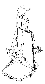
FIGURE 1 presents a front isometric view of a vehicle seat in an embodiment of
the
invention;
FIGURE 2 presents a rear isometric view of a vehicle seat in an embodiment of
the
invention;
TABLE 1 presents a bill of materials for a vehicle seat in an embodiment of
the
invention;
FIGURE 3 presents a rear isometric view of a vehicle seat in an embodiment of
the
invention, with the seat cushioning, seat back, occupant harness and antenna
system
removed. This Figure also shows how the tether system is pinned to the seat
pan and
vehicle end of the trailing arm;
FIGURE 4 presents a rear isometric view of a vehicle seat in an embodiment of
the
invention, with the seat cushioning, seat back, occupant harness and antenna
system
removed. This Figure also provides an exploded view of the seat pan assembly;
FIGURE 5 presents a side view of a vehicle seat in an embodiment of the
invention, with
cross-sectional details of the seat pan;
FIGURE 6 presents a cross-sectional detailed view of the seat pan,
corresponding to
portion A of Figure 5; and
FIGURES 7, 8 and 9 present photographs of an exemplary trailing arm.
While the invention has been described in connection with specific embodiments
and in
specific uses, various modifications thereof will occur to those skilled in
the art without
departing from the spirit and scope of the invention as set forth in the
appended claims.
6

Representative Drawing
A single figure which represents the drawing illustrating the invention.
Administrative Status

2024-08-01:As part of the Next Generation Patents (NGP) transition, the Canadian Patents Database (CPD) now contains a more detailed Event History, which replicates the Event Log of our new back-office solution.

Please note that "Inactive:" events refers to events no longer in use in our new back-office solution.

For a clearer understanding of the status of the application/patent presented on this page, the site Disclaimer , as well as the definitions for Patent , Event History , Maintenance Fee  and Payment History  should be consulted.

Event History

Description Date
Inactive: Dead - RFE never made 2016-06-01
Application Not Reinstated by Deadline 2016-06-01
Inactive: Abandon-RFE+Late fee unpaid-Correspondence sent 2015-06-01
Inactive: Office letter 2015-02-12
Letter Sent 2014-05-15
Reinstatement Requirements Deemed Compliant for All Abandonment Reasons 2014-05-14
Letter Sent 2014-01-17
Letter Sent 2013-11-06
Deemed Abandoned - Failure to Respond to Maintenance Fee Notice 2013-06-03
Application Published (Open to Public Inspection) 2011-12-01
Inactive: Cover page published 2011-11-30
Inactive: Reply to s.37 Rules - Non-PCT 2011-09-01
Inactive: Correspondence - Formalities 2011-09-01
Inactive: IPC assigned 2011-07-20
Inactive: Filing certificate - No RFE (English) 2010-10-28
Filing Requirements Determined Compliant 2010-10-28
Inactive: IPC assigned 2010-09-15
Inactive: First IPC assigned 2010-09-15
Inactive: IPC assigned 2010-09-15
Application Received - Regular National 2010-07-08

Abandonment History

Abandonment Date Reason Reinstatement Date
2013-06-03

Maintenance Fee

The last payment was received on 2015-05-22

Note : If the full payment has not been received on or before the date indicated, a further fee may be required which may be one of the following

  • the reinstatement fee;
  • the late payment fee; or
  • additional fee to reverse deemed expiry.

Please refer to the CIPO Patent Fees web page to see all current fee amounts.

Fee History

Fee Type Anniversary Year Due Date Paid Date
Application fee - standard 2010-06-01
MF (application, 2nd anniv.) - standard 02 2012-06-01 2012-04-05
Registration of a document 2013-10-18
Registration of a document 2013-12-06
Reinstatement 2014-05-14
MF (application, 3rd anniv.) - standard 03 2013-06-03 2014-05-14
MF (application, 4th anniv.) - standard 04 2014-06-02 2014-05-14
MF (application, 5th anniv.) - standard 05 2015-06-01 2015-05-22
Owners on Record

Note: Records showing the ownership history in alphabetical order.

Current Owners on Record
MED-ENG, LLC
Past Owners on Record
NEIL GRANT
Past Owners that do not appear in the "Owners on Record" listing will appear in other documentation within the application.
Documents

To view selected files, please enter reCAPTCHA code :


To view images, click a link in the Document Description column. To download the documents, select one or more checkboxes in the first column and then click the "Download Selected in PDF format (Zip Archive)" or the "Download Selected as Single PDF" button.

List of published and non-published patent-specific documents on the CPD .

If you have any difficulty accessing content, you can call the Client Service Centre at 1-866-997-1936 or send them an e-mail at CIPO Client Service Centre.


Document
Description 
Date
(yyyy-mm-dd) 
Number of pages   Size of Image (KB) 
Abstract 2010-06-01 1 20
Description 2010-06-01 6 209
Claims 2010-06-01 3 68
Drawings 2011-09-01 7 274
Representative drawing 2011-10-26 1 11
Cover Page 2011-11-17 1 41
Drawings 2010-06-01 8 1,357
Filing Certificate (English) 2010-10-28 1 166
Reminder of maintenance fee due 2012-02-02 1 113
Courtesy - Abandonment Letter (Maintenance Fee) 2013-07-29 1 172
Notice of Reinstatement 2014-05-15 1 163
Reminder - Request for Examination 2015-02-03 1 124
Courtesy - Abandonment Letter (Request for Examination) 2015-07-27 1 164
Correspondence 2010-07-09 1 23
Correspondence 2011-09-01 10 351
Fees 2014-05-14 1 24
Correspondence 2015-02-12 1 19