Language selection

Search

Patent 2706674 Summary

Third-party information liability

Some of the information on this Web page has been provided by external sources. The Government of Canada is not responsible for the accuracy, reliability or currency of the information supplied by external sources. Users wishing to rely upon this information should consult directly with the source of the information. Content provided by external sources is not subject to official languages, privacy and accessibility requirements.

Claims and Abstract availability

Any discrepancies in the text and image of the Claims and Abstract are due to differing posting times. Text of the Claims and Abstract are posted:

  • At the time the application is open to public inspection;
  • At the time of issue of the patent (grant).
(12) Patent: (11) CA 2706674
(54) English Title: CONCEALED CEILING PANEL SYSTEM
(54) French Title: SYSTEME DE PANNEAUX DE PLAFOND DISSIMULES
Status: Granted and Issued
Bibliographic Data
(51) International Patent Classification (IPC):
  • E04B 9/22 (2006.01)
  • E04B 9/24 (2006.01)
  • E04B 9/26 (2006.01)
(72) Inventors :
  • JAHN, PETER G. (United States of America)
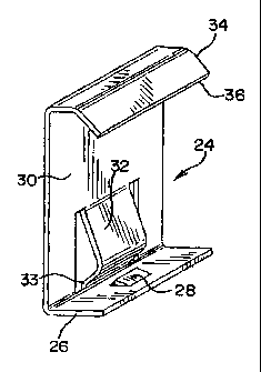
  • JANKOVEC, SCOTT G. (United States of America)
  • SMITH, THOMAS E. (United States of America)
(73) Owners :
  • ROCKWOOL A/S
(71) Applicants :
  • ROCKWOOL A/S (Denmark)
(74) Agent: FINLAYSON & SINGLEHURST
(74) Associate agent:
(45) Issued: 2011-08-16
(22) Filed Date: 2007-10-12
(41) Open to Public Inspection: 2008-04-16
Examination requested: 2010-06-16
Availability of licence: N/A
Dedicated to the Public: N/A
(25) Language of filing: English

Patent Cooperation Treaty (PCT): No

(30) Application Priority Data:
Application No. Country/Territory Date
60/852,044 (United States of America) 2006-10-16

Abstracts

English Abstract


Disclosed is a clip for securing a sheet metal ceiling panel to a suspended
ceiling
support grid wherein the ceiling panel has edges that are folded back to form
a hem and
the support grid comprises a plurality of runners having flanges thereon for
supporting the
ceiling panel. The clip has a first leg adapted to have at least a portion
thereof received
in the hem of the ceiling panel and a second leg extending generally
perpendicularly from
the first leg, the second leg including a detent extending toward the first
and adapted to
secure the clip to the flange of the runner. The invention also comprehends a
suspended
ceiling system with a plurality of such clips for securing the ceiling panel
to the grid.


French Abstract

La présente invention concerne un crampon pour la fixation d'un panneau de plafond en tôle métallique à un grillage de support de plafond suspendu, où le panneau de plafond comporte des rebords qui sont repliés pour former un rabat, et le grillage de support comporte une série de cadres-supports qui sont munis de saillies pour supporter le panneau de plafond. Le crampon de fixation comporte une première patte adaptée pour qu'une partie de ladite patte soit engagée dans le rabat du panneau de plafond, et une seconde patte généralement perpendiculaire à la première patte, la seconde patte comprenant une détente se prolongeant vers la première patte et adaptée pour fixer le crampon à la saillie du cadre-support. L'invention comprend également un dispositif de plafond suspendu muni d'une série de tels crampons pour fixer les panneaux de plafond au grillage de support.

Claims

Note: Claims are shown in the official language in which they were submitted.

-9-
WHAT IS CLAIMED IS:
1. A clip for securing a sheet metal ceiling panel to a suspended ceiling
support grid
wherein the ceiling panel has edges that are folded back to form a hem and the
support
grid comprises a plurality of runners having flanges thereon for supporting
the ceiling
panel, the clip comprising:
a first leg adapted to have at least a portion thereof received in the hem of
the
ceiling panel;
a second leg extending generally perpendicularly from the first leg, the
second leg
including a detent extending toward the first leg adapted to secure the clip
to the flange
of the runner.
2. The clip of claim 1 wherein the first leg further comprises a tab adapted
to be
received in a corresponding aperture in the hem of the ceiling panel.
3. The clip of claim 1 wherein the detent has a free end adapted to engage an
edge
of the flange of the runner.
4. A suspended ceiling system comprising:
at least one sheet metal ceiling panel, the panel having a plurality of edges,
the
edges being folded back to form a hem about the periphery of the panel;
a support grid comprising a plurality of runners having flanges thereon; and
a plurality of clips for securing the sheet metal panel to the grid system,
the clips
comprising a first leg received in the hem of the ceiling panel, a second leg
extending
generally perpendicularly to the first leg, and a detent extending from the
second leg
toward the first leg.

-10-
5. The system of claim 4 wherein the hem of the ceiling panel includes an
aperture
for locating each clip and the first leg of the clip includes a tab received
in the aperture.
6. The system of claim 4 or 5 wherein the detent on the clip engages the
flange of
the runner.

Description

Note: Descriptions are shown in the official language in which they were submitted.


CA 02706674 2010-06-16
CONCEALED CEILING PANEL SYSTEM
This application is a divisional application of Canadian Patent
File No. 2,606,754 filed October 12th, 2007.
FIELD AND BACKGROUND
[0001] The present invention relates to a suspended ceiling system and, more
particularly,
a ceiling panel adapted for use in a curved suspended ceiling system in which
the suspension
grid is substantially concealed from view by the ceiling panels and in which
the panels can be
shipped in a flat configuration. In one aspect of the invention, the ceiling
panel includes tabs
formed integrally therewith for attaching the ceiling panel to the suspension
grid. In second
aspect, a clip is provided for securing the ceiling panel to a suspension
grid.
[0002] Curved suspended ceiling systems are becoming increasingly popular.
This
application discloses a unique curved suspension grid system in which the main
runners are
secured to a plurality of primary carriers that are oriented transversely to
the main runners and
extend substantially the width of the suspended ceiling.

CA 02706674 2010-10-25
-2-
[0003]As shown in the referenced application, the ceiling panels are supported
directly on the top surfaces of the flanges of the main runners, as is typical
in many
suspended ceiling systems, and are secured in place by hold-down clips that
are
placed over the reinforcing bulb of the runner. However, it is sometimes
desirable,
usually for aesthetic reasons, to disguise or hide the supporting grid system
for the
panels. While this has been done for flat ceiling grids, the problems of
creating a
curved ceiling panel system that substantially conceals the support grid
system have
not been adequately addressed before the present invention.
SUMMARY OF THE INVENTION
[0004 The present invention comprises a novel flexible ceiling panel
preferably
formed from sheet metal, such as aluminum sheet. Each ceiling panel has a
generally
rectangular shape (corresponding in width to the spacing between the main
runners)
and is formed with a hem on all four edges.
[0005 ]Two different approaches for securing the panels to the grid system are
contemplated. In a first embodiment of the present invention, a series of
bendable
tabs are formed integrally with the hem of the panel. To secure the panel to
the
associated grid system, the tabs are folded upwardly and outwardly from the
panel
along two axes to secure the panel to the grid system.

CA 02706674 2010-06-16
-3-
0006 ) In a second embodiment, a plurality of separate spring clips is used to
secure
the panel to the grid system. Each clip includes a first leg adapted to have
at least a
portion thereof received in the hem of the ceiling panel. A second leg extends
generally perpendicularly from the first leg and includes a detent extending
toward the
first leg, the detent being adapted to secure the clip to the flange of the
runner. In one
embodiment of the clip, the detent is adapted to engage an edge of the flange
of the
runner. In a second embodiment, the detent is adapted to engage an upper
surface of
the flange of the runner.
[ 0007 ] In a further aspect of the clip, the clip may include an angled
segment
extending from the second leg having a free end that is adapted to engage the
flange
of the runner during installation of the ceiling panel into the support grid.
BRIEF DESCRIPTION OF THE DRAWINGS
[ 0008 1 Fig. 1 is a plan view of a ceiling panel according to a first
embodiment of the
present invention.
[ 0009 Fig. 2 is a fragmentary view of the ceiling panel of Fig. 1, enlarged
to show
detail.
[00010]Figs. 3 and 4 are fragmentary perspective views illustrating the
process for
securing the ceiling panel of Fig. 1 to a grid member or runner.

CA 02706674 2010-06-16
-4-
[00011]Fig. 5 is a cross-sectional view taken along line 5-5 in Fig. 4 showing
the
ceiling panel of Fig. 1 secured to a grid member.
[0001 2]Figs. 6, 8 and 10 illustrate a clip for securing a hemmed ceiling
panel to a grid
member, with Fig. 6 being a perspective view showing the relationship between
the
clip, the ceiling panel and the grid member, Fig. 8 being a cross-sectional
view taken
along line 8-8 of Fig. 6, and Fig. 10 being a perspective view of the clip.
( 00013 Figs. 7, 9 and 11 illustrate a variation of the clip of Figs. 6, 8 and
10 for
securing a hemmed ceiling panel to a grid member.
[00014]Fig. 12 is a perspective view of a tool designed to assist in removal
of a ceiling
panel secured to a grid member by the clip of Figs. 7, 9 and 11.
DETAILED DESCRIPTION
( 00015 1 With reference to the accompanying drawings, the basic construction
of a
flexible ceiling panel 10 in accordance with the present invention is shown.
Specifically, the panel 10 is made from sheet metal, and preferably from
aluminum
sheet of an aluminum alloy such as 3003 H-14 or 3105 aluminum alloy. The panel
10
is typically 24 inches in width to match a standard grid module. However, a 30-
inch
width is also possible. The panel 10 may be perforated to improve acoustical
performance. Additionally, acoustical materials (such as non-woven matt and

CA 02706674 2010-06-16
-5-
insulation pads, rolls or batts) can be added to the back side of the panel 10
to
improve sound absorption and reduce sound transmission.
000161The panel 10 has an edge perimeter comprising a hem 12 formed by folding
the edges of the panel 10 back on themselves on all four sides. A preferred
width for
the hem is .472 inches, although other widths may be selected without
departing from
the invention. The panel hem design allows for the panel to curve to adapt to
the
profile of the suspension grid. The panels can conform to varying convex
and/or
concave contours in a single panel, with lengths up to 12 feet being
contemplated,
depending upon handling limitations.
00017 1 With reference to Figs. 1-5, a plurality of tabs 14 are formed
integrally with
the hem 12 spaced at intervals about the perimeter of the panel. As
illustrated, the
tabs 14 are generally rectangular in shape and have an overall dimension of 1
1/2
inches by 11/16 inches, although other shapes and dimensions may be used. Each
tab 14 is bendable relative to the hem 12 along a first axis to an angle of
approximately
90 with respect to the panel 10. A minor portion 14a (measuring
approximately 1/2
inch by 11/16 inch) of each tab 14 is bendable along a second axis at an
obtuse angle
with respect to the major portion 14b of the tab 14 to provide the portion of
the tab that
engages the flange 17a of the runner 17. The tab 14 is provided with slots or
cutouts

CA 02706674 2010-06-16
-6-
16 along the first and second axes that facilitate bending of the tab as
described above, although
other techniques for predisposing the clip to bend at the desired locations
may be used, such as
pre-creasing the tab 14 along the first and second axes.
[00018] The panels 10 are shipped with the tabs 14 unbent, as shown in, e.g.,
Figs. 1-3.
with reference to Figs. 4 and 5, the panels 10 are secured to a grid member or
runner 17 by first
partially bending the tabs 14 along the first axis to help guide the panel 10
into the grid opening
from below. Then, after the panel 10 is in position in the grid opening, the
tabs 14 are bent
along the second axis so that the minor portion 14a thereafter engages the
back side of the
horizontal flange 17A of the runner 17.
[00019] With reference to Figs. 6-11, a second system for securing the ceiling
panel 10
to the grid system is shown. In this system, a hemmed sheet metal panel 10 is
also provided.
However, instead of having tabs being formed integrally therewith, the hems 12
include pre-
punched holes 22 (best seen in Figs. 6 and 7) at spaced intervals that
cooperate with a clip,
generally designated 24, to locate and appropriately space the clips and to
secure the clips to the
panel.
[00020] The clip 24 is generally L-shaped, with a first or lower leg 26 having
a tab 28
being bent upwardly therefrom that is of a size and shape so that it can be
received in

CA 02706674 2010-06-16
-7-
the pre-punched hole 22 in the hem 12. A second, longer leg 30 of the clip
includes a spring
tongue or detent 32 that extends generally toward the first leg 26 of the
clip. With reference
to Figs. 6, 8 and 10, the free end 33 of the detent 32 extends toward the edge
of the panel 10,
when the clip 24 is installed thereon, with an intermediate portion of the
detent 32 being curved
or bowed so as to overlie the flange 17a of the runner 17. During installation
of the panel into
the grid, the curved portion of the detent 32 pulls the panel 10 upwards and
holds the panel hem
12 against the face of the grid. The clip 24 also includes an upper angled
portion 34 that allows
the panel be initially installed below the face of the grid, with the free end
36 of the angled
portion resting on the flange of the runner, thus allowing the panels 10 to be
installed without
the clip 24 interfering with the reinforcing bulb of the runners in the grid.
[00021] The panels secured to a grid by means of the clip 24 of Figs. 6, 8 and
10 can be
removed or demounted without a special tool by simply pulling downward at the
edge of the
panel and inserting a screw driver or bladed tool at the edge. By prying
downwardly, the detent
32 can be disengaged from the flange of the runner and the panel lowered so
that the free end
of the upper angled portion 34 of the clip 24 rests on the flange of the
runners.
Final demounting of the panels is then accomplished by

CA 02706674 2010-06-16
-8-
bending the vertical leg 30 by applying forger pressure to provide clearance
between the angled
portion 34 of the clip 24 and the flange 17a of the runner 17.
[00022] Alternatively, and as illustrated in Figs. 7, 9 and 11, the spring
tongue or detent
32 may be shortened so that it extends over the inner edge of the hem. When
the panel is
installed, using this clip, the free end 33 of the detent 32 engages the upper
surface of the flange
17a of the support runner 17. As such, the spring clip 24 locks the panel in
place, clamping the
flange 17a of the grid between the detent 32 and the ceiling panel 10.
Consequently, a special
tool is required to remove a panel utilizing this clip embodiment, such as the
tool 40 shown in
Fig. 12. The tool 40 has a working end 42 that is inserted between the hem of
the panel and
the bottom of the flange of the runner and then slid along the edge thereof to
disengage the
detent 32 from the top of the flange.
[00023] Thus, a system has been provided for securing a ceiling panel to a
grid system
in a manner that conceals the grid system from view. While the inventions
disclosed in the
present application are intended to be used with a curved suspension grid,
they may also be used
with a standard flat suspension grid without departing from the invention.

Representative Drawing
A single figure which represents the drawing illustrating the invention.
Administrative Status

2024-08-01:As part of the Next Generation Patents (NGP) transition, the Canadian Patents Database (CPD) now contains a more detailed Event History, which replicates the Event Log of our new back-office solution.

Please note that "Inactive:" events refers to events no longer in use in our new back-office solution.

For a clearer understanding of the status of the application/patent presented on this page, the site Disclaimer , as well as the definitions for Patent , Event History , Maintenance Fee  and Payment History  should be consulted.

Event History

Description Date
Maintenance Request Received 2024-10-04
Maintenance Fee Payment Determined Compliant 2024-10-04
Letter Sent 2023-04-21
Change of Address or Method of Correspondence Request Received 2023-03-24
Inactive: Multiple transfers 2023-03-24
Common Representative Appointed 2019-10-30
Letter Sent 2015-02-18
Inactive: Correspondence - Transfer 2014-12-18
Letter Sent 2014-10-07
Grant by Issuance 2011-08-16
Inactive: Cover page published 2011-08-15
Pre-grant 2011-05-31
Inactive: Final fee received 2011-05-31
Letter Sent 2011-02-03
Notice of Allowance is Issued 2011-02-03
Inactive: Approved for allowance (AFA) 2011-02-01
Amendment Received - Voluntary Amendment 2010-10-25
Inactive: S.30(2) Rules - Examiner requisition 2010-09-21
Inactive: Cover page published 2010-08-04
Inactive: IPC assigned 2010-07-21
Inactive: First IPC assigned 2010-07-21
Inactive: IPC assigned 2010-07-21
Letter sent 2010-07-15
Application Received - Regular National 2010-07-13
Letter Sent 2010-07-13
Divisional Requirements Determined Compliant 2010-07-13
All Requirements for Examination Determined Compliant 2010-06-16
Application Received - Divisional 2010-06-16
Request for Examination Requirements Determined Compliant 2010-06-16
Application Published (Open to Public Inspection) 2008-04-16

Abandonment History

There is no abandonment history.

Maintenance Fee

The last payment was received on 2010-06-16

Note : If the full payment has not been received on or before the date indicated, a further fee may be required which may be one of the following

  • the reinstatement fee;
  • the late payment fee; or
  • additional fee to reverse deemed expiry.

Please refer to the CIPO Patent Fees web page to see all current fee amounts.

Owners on Record

Note: Records showing the ownership history in alphabetical order.

Current Owners on Record
ROCKWOOL A/S
Past Owners on Record
PETER G. JAHN
SCOTT G. JANKOVEC
THOMAS E. SMITH
Past Owners that do not appear in the "Owners on Record" listing will appear in other documentation within the application.
Documents

To view selected files, please enter reCAPTCHA code :


To view images, click a link in the Document Description column. To download the documents, select one or more checkboxes in the first column and then click the "Download Selected in PDF format (Zip Archive)" or the "Download Selected as Single PDF" button.

List of published and non-published patent-specific documents on the CPD .

If you have any difficulty accessing content, you can call the Client Service Centre at 1-866-997-1936 or send them an e-mail at CIPO Client Service Centre.


Document
Description 
Date
(yyyy-mm-dd) 
Number of pages   Size of Image (KB) 
Description 2010-06-16 8 257
Abstract 2010-06-16 1 25
Drawings 2010-06-16 4 120
Claims 2010-06-16 1 21
Representative drawing 2010-08-04 1 10
Cover Page 2010-08-04 2 47
Description 2010-10-25 8 257
Abstract 2010-10-25 1 18
Claims 2010-10-25 2 41
Cover Page 2011-07-14 2 44
Confirmation of electronic submission 2024-10-04 2 68
Acknowledgement of Request for Examination 2010-07-13 1 177
Commissioner's Notice - Application Found Allowable 2011-02-03 1 162
Correspondence 2010-07-15 1 37
Correspondence 2011-05-31 1 37