Note: Descriptions are shown in the official language in which they were submitted.
CA 02707397 2010-06-14
1
A Tool Box Storage Assembly
General Background
Field of the Invention
The present invention generally relates to a tool box
storage assembly and more particularly to a tool box storage
assembly having components which cooperatively allow the
assembly to be selectively formed in a wide variety of
configurations to meet the needs of a diverse group of users
and applications.
General Background
Toolbox storage assemblies are generally used to
selectively store tools and other items in order to allow
these stored tools and other items to be selectively retrieved
for use in certain applications. After use they must be re-
stored until needed again. One non-limiting example of such an
application involves the selective storing and use of
automotive tools.
While such toolbox assemblies do allow certain items to
be stored and later retrieved, they suffer from some
drawbacks. By way of example and without limitation, these
prior and current toolbox assemblies are usually of a fixed
configuration and while this storage configuration may be fine
CA 02707397 2010-06-14
2
for a certain type or amount of items, it may be unsuitable
for other applications having different numbers and shapes of
tools and implements. Storage needs change over time, and a
"fixed type" of configuration may need to be replaced over
time, to meet these ever changing needs, thereby undesirably
increasing cost and expense to the user. Moreover, these prior
and current toolbox assemblies are not readily adapted to
address the needs of a wide variety of dissimilar applications
and therefore their overall utility is impaired.
There is therefore a need for and it is a non-limiting
object of the present inventions to provide a tool box
assembly which may have a variety of selectable storage
configurations which allow the tool box assembly to serve the
needs of a wide variety of dissimilar applications and users
and to meet the ever-changing needs of a user. These and other
non-limiting objects are met by the various inventions
detailed below.
Summary Of The Invention
It is a first non-limiting object of the present
invention to provide a tool box assembly which overcomes some
or all of the previously delineated drawbacks of prior and
currently utilized tool box assemblies.
CA 02707397 2010-06-14
3
It is a second non-limiting object of the present
invention to provide a tool box assembly which overcomes some
or all of the previously delineated drawbacks of prior and
currently utilized tool box assemblies and which, by way of
example and without limitation, allow a variety of dissimilar
applications and needs to be addressed.
It is a third non-limiting object of the present
invention to provide a tool box assembly which allows for the
selective use of a base storage component and at least one of
a top and a side storage component, each of the top and side
components being adapted to be easily and removably attached
to the base storage component.
According to a first non-limiting aspect of the present
invention, a tool box assembly is provided and includes a
first cabinet assembly; a plurality of wheels which are
operatively coupled to the first cabinet assembly; a second
cabinet assembly which is removably and selectively coupled to
a first surface of the first cabinet assembly; and a hutch
which is removably and selectively coupled to a second surface
of the first cabinet assembly.
According to a second non-limiting aspect of the present
invention, a tool box assembly is provided and includes a
first cabinet assembly; a plurality of wheels which are
operatively coupled to the first cabinet assembly; and a side
CA 02707397 2010-06-14
4
cabinet assembly which is selectively coupled to the first
cabinet assembly and which includes an internal storage cavity
and a door which is selectively movable from a first closed
position to a second extended position and wherein the door
includes a back surface which communicates with the internal
storage cavity when the door is placed in the closed position
and which includes a pair of substantially similar and
linearly coextensive tracks; and a plurality of trays which
are selectively and removably coupled to the tracks, and
wherein at least one of the plurality of trays has a first top
surface which has a plurality of holes and a second open
bottom surface.
According to a third non-limiting aspect of the present
invention, a tool box assembly is provided and includes a base
portion having a plurality of stacked drawers which are each
selectively movable from a first respective closed position to
a second respective open position, wherein the base portion
includes an internal cavity into which the plurality of
drawers are movably disposed; a side door which is
selectively movable from a first closed position in which the
door overlays the plurality of drawers and cooperates with the
plurality of drawers to form an internal storage cavity, to
second open position in access to the internal storage cavity
is allowed; a plurality of wheels which are coupled to the
CA 02707397 2010-06-14
base portion; and a top hutch portion which is removably
attached to the base portion.
These and various other aspects, advantages, and objects
of the various inventions will become apparent from a reading
5 of the detailed description of the preferred embodiment of the
invention, including but not limited to the subjoined claims,
and by reference to the included drawings.
Brief Description Of The Drawings
Figure 1 is a perspective view of a tool box storage
assembly which is made in accordance with the teachings of a
preferred, although non-limiting, invention and which further
depicts the selective combination of a bottom cabinet and a
side cabinet assembly which are each made in accordance with
the teachings of the preferred embodiment of the inventions.
Figure 2 is a perspective view of the side cabinet
assembly which is shown in Figure 1 in a selective open
position.
Figure 3 is perspective view of a side cabinet assembly
which is made in accordance with the teachings of an alternate
embodiment of the invention.
Figure 4 is a perspective view of the side cabinet which
is shown in Figure 3 in a selective open position.
CA 02707397 2010-06-14
6
Figure 5 is perspective unassembled view of the bottom
and side cabinets which are shown in Figure 1.
Figure 6 is a perspective unassembled view of the bottom
and side cabinets which are made in accordance with the
teachings of an alternate embodiment of the invention.
Figure 7 is a fragmented enlarged view taken around
Fragment "7".
Figure 8 is a fragmented enlarged view taken around
Fragment "8".
Figure 9 is a fragmented enlarged portion of the mated
side and bottom cabinets.
Figure 10 is a partially unassembled perspective view of
the bottom cabinet which is shown in Figure 1 and further
shown in a selective open position.
Figure 11 is an enlarged perspective and unassembled view
of a portion of the bottom cabinet which is shown in Figure
10.
Figure 12 is a view taken in the direction of view arrow
"12"
Figure 13 is a view similar to that which is shown in
Figure 10 but with the drawers removed.
CA 02707397 2010-06-14
7
Figure 14 is an unassembled perspective view of a first
portion of a locking assembly which may be selectively and
operatively deployed within the bottom cabinet portion which
is shown in Figure 13.
Figure 15 is an unassembled perspective view of a second
portion of a locking assembly which may be selectively and
operatively deployed within the bottom cabinet portion which
is shown in Figure 13.
Figure 16 is an unassembled perspective view of a third
portion of a locking assembly which may be selectively and
operatively deployed within the bottom cabinet portion which
is shown in Figure 13.
Figure 17 is an unassembled and perspective view of a
fourth portion of a locking assembly which may be selectively
and operatively deployed within the bottom cabinet portion
which is shown in Figure 13.
Figure 18 is an unassembled and perspective view of a
fifth portion of a locking assembly which may be selectively
and operatively deployed within the bottom cabinet portion
which is shown in Figure 13.
Figure 19 is an unassembled and perspective view a sixth
portion of a locking assembly which may be selectively and
CA 02707397 2010-06-14
8
operatively deployed within the bottom cabinet portion which
is shown in Figure 13.
Figure 20 is an unassembled and perspective view of a
seventh portion of a locking assembly which may be selectively
and operatively deployed within the bottom cabinet portion
which is shown in Figure 13.
Figure 21 is an unassembled and perspective view an
eighth portion of a locking assembly which may be selectively
and operatively deployed within the bottom cabinet portion
which is shown in Figure 13.
Figure 22 is a perspective view of the bottom cabinet
which is shown in Figure 10 and further showing the back door
being selectively opened.
Figure 23 is an unassembled perspective view of back door
portion which is shown in Figure 22.
Figure 24 is a perspective view of a tool box assembly
which is made in accordance with the teachings of an alternate
and non-limiting embodiment of the inventions.
Figure 25 is a perspective view of the tool box assembly
which is shown in Figure 24 and shown in a selective open
position.
CA 02707397 2010-06-14
9
Figure 26 is a perspective view of the top or hutch
portion of the tool box assembly which is made in accordance
with the teachings of an alternate and non-limiting embodiment
of the invention.
Figure 27 is a perspective and enlarged view of a portion
of the hutch portion which is shown in Figure 26.
Figure 28 is a perspective and enlarged view of a second
portion of the hutch portion which is shown in Figure 26.
Figure 29 is a perspective and enlarged view of a third
portion of the hutch portion which is shown in Figure 26.
Figure 30 is a side view of the third portion which is
shown in Figure 29.
Figure 31 is a perspective and enlarged view of a fourth
portion of the hutch portion which is shown in Figure 26.
Figure 32 is a side view of the fourth portion which is
shown in Figure 31.
Figure 33 is a perspective and enlarged and unassembled
view of a fifth portion of the hutch portion which is shown in
Figure 26.
Figure 34 is a side view of the fifth portion which is
shown in Figure 33.
CA 02707397 2010-06-14
Figure 35 is a perspective and enlarged and unassembled
view of a sixth portion of the hutch portion which is shown in
Figure 26.
Figure 36 is a side view of the sixth portion which is
5 shown in Figure 35.
Figure 37 is a perspective and enlarged and unassembled
view of a seventh portion of the hutch portion which is shown
in Figure 26.
Figure 38 is an enlarged view of a portion of the seventh
10 portion which is shown in Figure 37.
Figure 39 is a perspective and unassembled view of an
eighth portion of the hutch portion which is shown in Figure
26.
Figure 40 is a top and unassembled view of a ninth
portion of the hutch portion which is shown in Figure 26.
Figure 41 is a side view of a tenth portion of the hutch
portion which is shown in Figure 26.
Figure 42 is a top view of an eleventh portion of the
hutch portion which is shown in Figure 26.
Figure 43 is a perspective view of a twelfth portion of
the top portion which is shown in Figure 26.
CA 02707397 2010-06-14
11
Figure 44 is an exploded perspective view of the pin
which is shown in Figure 43.
Figure 45 is a perspective view of the hutch portion
which is shown in Figure 26 is combination with the lock
portion which is shown in figure 42.
Detailed Description Of The Preferred Embodiments of The
Invention
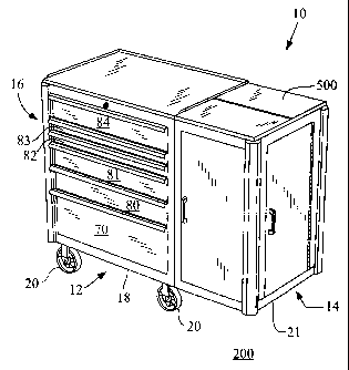
Referring now to Figure 1, there is shown a tool box
assembly 10 which is made in accordance with the teachings of
the preferred, although non-limiting embodiment of the
invention.
In this non-limiting preferred embodiment, the assembly
10 includes a base or central cabinet or storage portion 12
and a side cabinet or storage cabinet 14 which is selectively
and removably coupled to the portion 12 as will be more fully
explained or delineated later. That is, each portion 12, 14
may respectively be used on a "stand-alone" basis or
selectively joined in order to meet a wide range of ever
changing user needs. Portions 12 and 14 are therefore
independent, but selectively "joinable" storage components.
Particularly, the portion 12 includes a hollow and
generally cubic shaped body 16 having a bottom surface 18 to
which a plurality of substantially identical wheels 20 are
CA 02707397 2010-06-14
12
coupled. In the most preferred embodiment of the invention,
four such wheels 20 are deployed upon the surface 18 (i.e.,
each unique corner of the surface 18 has a unique one of the
wheels 20 operatively deployed upon it). In a similar manner,
wheels may be operatively disposed upon bottom surface 21 of
side cabinet 14.
As is perhaps shown best in Figures 1 and 10, the hollow
body 16 of base or central cabinet 12 forms a central storage
cavity 22 which is adapted to allow various items to be
removably placed, for storage, and then to be retrieved for
use in a particular application. After use, these items may be
returned to the storage cavity 22, until needed again. The
body 16 includes a generally flat top portion 26 which is
coupled to the edge 11 of the body 16 by a pair of
substantially identical hinges 28, 30 and is therefore
selectively movable from a first open position, shown in
Figure 10, in which the top portion 26 exposes the central
cavity 22, to a closed position in which the top portion 26
overlays and closes the cavity 22.
The body 16 further includes a first generally flat side
door 31 which is coupled to the body 16 along edge 40 by the
use of a pair of substantially identical hinges 42, 44, and a
second side door 48 which is substantially identical to the
side door 31 and which is also hingedly coupled to the body
CA 02707397 2010-06-14
13
16. Side door 31 is selectively movable from first open
position, shown in Figure 10 in which the door 31 is remote
from the rest of the body 16, to a second closed position in
which the door 31 wholly lies in a plane which is
perpendicular to the plane containing the top 26 when the top
26 is in a selectively closed position. Similarly, the side
door 48 is also selectively movable from a first open position
which is shown in Figure 10 and in which the side door 48 is
remote from the rest of the body 16, to a second closed
position in which the door 48 wholly lies in a plane which is
perpendicular to the plane which contains the top 26 when the
top 26 is in a selectively closed position. The side doors 31,
48 lie upon opposite sides of the body 16.
Further, in the most preferred although non-limiting
embodiment of the invention, a rib panel 60 is formed and/or
disposed within the body 16 to prevent communication between
the internal storage cavity 22 and the door 31. That is, when
the door 31 is in a selective open position, the panel 60
prevents communication with and access to the internal storage
cavity 22, through the open door 31. A similar panel (not
shown) is also disposed within the body 16 to prevent
communication between the internal storage cavity 22 and the
door 48 and to prevent access to the internal storage cavity
22 when the door 48 is placed in a selective open position.
CA 02707397 2010-06-14
14
Moreover, it should be apparent that the door 31 and the panel
60 cooperate to form a second storage compartment located
between the internal door surface 61 and the panel 60, and
that a similar side storage compartment is formed between the
internal surface 49 of the door 48 and the panel with which it
communicates (not shown). These two secondary storage
compartments increase the amount of overall storage space
provided by the assembly or component 12 and are respectively
formed when the doors 31, 48 are respectively closed.
Additionally, in the most preferred although non-limiting
embodiment of the invention, a pair of substantially identical
pockets 64, 66 are formed within the body 16 and these pockets
64, 66 are generally rectangular and are each adapted to
selectively and removably receive an insert or trough 68. Each
insert 68 is selectively and removably placed within one of
the pockets 64, 66 and these removable inserts are adapted to
selectively receive and store parts and items for use within
one or more applications. The removable nature of the inserts
or troughs 68 allows the contained items and material to be
easily and quickly transported to the place where the
contained items are needed or to a place where items are
located which are to be placed in the insert(s) 68.The
removable nature of the inserts or troughs 68 enhances the
usefulness of the assembly 12.
CA 02707397 2010-06-14
The body 16 further includes a generally flat front door
70 which is coupled to the body 16 along edge 72 by a hinge
member 74 and which is movable from a first open position
(shown in Figure 10) in which access to the central storage
5 compartment 22 is allowed, to a second closed position in
which the door 70 overlays the storage compartment 22. The
body 16 also includes drawers 80, 81, 82, 83, and 84 which are
each movably deployed within the body 16 by the use of
respective and opposed tracks 3, 5 and which are each
10 independently movable from a respective closed position in
which the drawers respectively 80-84 reside within the
internal storage cavity 22, to a respective open position in
which the respective containment cavity 86 is removed from the
internal storage cavity 22 and exposed. Respective track pairs
15 3, 5 are fixed to opposed sides of a drawer 70,80,81, 82, 83,
and 84 and are slidably coupled to and disposed within the
body 16( e.g., each track 3, 5,is slidably disposed in a track
which is fixed within the body 16). It should be apparent that
even when all the drawers 80-84 are respectively in a
selectively closed position, when the top member 26 is placed
in a selectively opened position, the storage compartment 86
of the drawer 84 is accessible. Also, when top member 26 is in
a closed position, the cavity 22 may be accessed by opening
drawer 84.
CA 02707397 2010-06-14
16
Further, as is perhaps best shown in Figures 1, 10, 11,
and 12 in the most preferred although non-limiting aspect of
the invention, upon the internal surface 61 there is deployed
a pair of substantially identical and linearly coextensive
tracks 91, 93. The tracks 91, 93 are equidistantly spaced,
linearly coextensive, and parallel to each other. Each track
91, 93 include equidistantly spaced and substantially
identical clips 100. Each clip 100 on track 91 is linearly and
horizontally aligned with a unique clip on track 93. Each clip
100 includes a pair of flexible and substantially identical
arms 101, 102 which are deployed upon a generally flat and
flexible base 103. Each base 103 may be welded or otherwise
coupled to a track 91, 93 by a conventional technique and each
respective pair of arms 101, 102 of a clip 100 are linearly
aligned and substantially identical.
The assembly 12 includes at least one member 105 which
has a generally flat bottom surface 107 having a plurality of
holes 109 and side portions 110, 111, 112, and 113 which
cooperate with the surface 107 to form a cavity 115. Side
surface 113 includes a first plurality of generally "cross
shaped" openings 120 which are aligned along a first axis 121
and a second plurality of openings 122 which are aligned along
a second axis 123. The openings 122 and 120 are each
substantially identical and each opening 120 is linearly and
CA 02707397 2010-06-14
17
horizontally aligned with a unique one of the openings
122.Axis 121 is an axis of symmetry of openings 120 and axis
123 is an axis of symmetry of openings 122.
Each opening 122 and 120 is adapted to allow for receipt
and retention of arms 101, 102 and in this manner the openings
120 are each respectively adapted to receive clips 100 of
track 91 while openings 122 are each respectively adapted to
receive clips 100 of track 93, thereby allowing the member 105
to be placed upon any desired location on the tracks 91, 93
and the placement is removable in that the clips 100, once
received by and retained within the openings 120, 122 may be
forcibly and selectively dislodged. That is, each opening
120, 122 includes a slit 141 through which arms 101, 102 are
placed and then the "placed" arms 101, 102 are made to contact
side 113 and the length 119 of the slit 121 is only slightly
larger than the length 125 of the substantially identical
clips 100, thereby ensuring that once a pair arms 101, 102 are
selectively placed through a slit 141, the clip 100 is not
readily removable (e.g., it is not likely that the arms 101,
102 will "slide out" of the slit 141 due to the contact with
side 113 and due to the fact that the length 119 is only
slightly larger than length 125). It should be appreciated
that openings 120, 121 are each "complementary" to clips 100
in that openings 120, when receiving the arms 101, 102, allow
CA 02707397 2010-06-14
18
clips 100 to selectively fasten the member 105 within the
assembly 12 in the manner described above. Clips 100 within
track 93 are aligned along vertical axis of symmetry 1700 and
clips 100 within track 91 are aligned along vertical axis of
symmetry 1800.
Importantly, the openings 120, 122 may selectively
receive the clips 100 in the manner which is shown in Figure
11 (with the surface 107 positioned as shown). In this
selective configuration, the surface 107 (namely the openings
109) are adapted to receive tools and other implements (such
as by way of example and without limitation screw drivers) and
to allow the received implements to be easily removed for
later use. Alternatively, the surface 107, in the shown
position, may be used to contain loose parts and material
which are larger than holes 109. In another non-limiting
embodiment, the holes 109 are not formed in the surface 107.
In another selectable configuration, as is best shown in
Figure 10, the surface 107 may be made to face downward (in a
direction toward the surface 200 upon which the assembly 10
rests). This is accomplished by selectively rotating the
member 105, shown in Figure 11, by about one hundred and
eighty degrees in a clockwise manner. In this manner, screw
drivers and other implements may be easily placed and removed
from the formed holes 109. These clips 100 allow the members
CA 02707397 2010-06-14
19
105 to be placed on the tracks 91, 93 in at least two distinct
positions (either surface 107 or cavity 115 may face away from
surface 200).
As is further shown in Figure 10, another non-limiting
body of a storage tray or member is represented by member 212
(a plurality of members 212 may be utilized) which has a flat
base portion 214 which has a side portion 201 which is
substantially similar to side 113 (i.e., the portion 201 is
generally flat and has openings 120, 122). The member 212
further includes a generally flat ledge portion 215 which
orthogonally protrudes from the surface 201 and away from
surface 61. The member 212 includes a plurality of
equidistantly spaced and substantially similar flexible arms
217 which all wholly reside in the same plane and this plane
is parallel to the plane which wholly contains the portion
201. The member 212 also includes a plurality of second
flexible members 220 which are substantially similar and
equidistantly positioned along edge 221 and are co-planar. The
members 220 are orthogonally positioned with respect to
portion 212 and protrude away from surface 61. Each arm 217 is
positioned above a unique one of the members 220. It should be
appreciated that surface 201 is made to selectively receive
clips 100 and to therefore be selectively placed upon tracks
91, 93 in the manner which has been previously described.
CA 02707397 2010-06-14
It should be apparent that the tools and other implements
may be selectively placed between adjacent arms 217 and/or
between adjacent arms or members 220, thereby further
facilitating the storage of a plurality of dissimilar
5 implements and members. It should be apparent that the two
track system (i.e., columns 91, 93) allows a user to select
which, if any type or number of members 212 and/or 105, they
desire to utilize and then to determine the respective amount
and placement of the selected members 212, 105. The
10 configurations can be easily changed at any time by simply
removing a member 105, 212, putting another member 105, 212 in
its place, moving the removed member 105, 212 to a different
location, or turning the member 105 to a new position. This
feature allows the assembly 12 to be utilized in a wide
15 variety of applications and to meet the needs of ever changing
applications which require new and different implements and
tools. This "two track" system thus increases the versatility
and usefulness of the entire tool box assembly 12.
In another non-limiting embodiment, as is best perhaps
20 shown in Figure 22, a back door 302 is coupled to the edge 304
by the use of hinge 306 and this door 302 is selectively
movable from a first open position (which is shown in Figure
22) in which access to the internal cavity 22 is allowed to a
second closed position in which the door 302 overlays the
CA 02707397 2010-06-14
21
cavity 22 and prevents access to the cavity 22, through the
door passage. In one non-limiting embodiment, the door 302
includes a generally flat back surface 308 and two
substantially identical side surfaces 310,312 which
orthogonally extend from and integrally terminate into the
back surface 308 along respective edges 314, 316. Each side
surface 310, 312 may have two respective tracks 91, 93,
thereby allowing members 105 and 212 to be placed upon the
surfaces 310, 312. A handle 320 may be deployed upon the
surface 308 to facilitate the selective movement of the door
302.
Referring now to Figure 23, there is shown an alternate
embodiment of the door 302. In this alternate and non-limiting
embodiment, two tracks 400, 401 of substantially identical
clips 404 appear on each of the respective side surfaces 310,
312. Each clip 404 includes a generally flat back portion 405
which is attached to one of the surfaces 310, 312 by glue or
some other conventional fastening technique, and a front
portion 407 which cooperates with the back portion 405 to form
a groove 409. The tracks 400, 401 on surface 312 are linearly
coextensive and of equal length and are parallel to each
other. The tracks 400, 401 on surface 310 are similarly
linearly coextensive and of equal length and are parallel to
each other. Each clip 404 of track 401 on surface 312 is
CA 02707397 2010-06-14
22
linearly and horizontally aligned with a unique one of the
clips 404 on track 401 on surface 310 and each clip 404 of
track 401 on surface 312 is linearly aligned with a unique one
of the clips 404 on track 401 on surface 310.
A container 430 may be selectively attached and removed
from the back door 302. As shown, container or member 430
includes a generally flat top surface 432 having a plurality
of holes 434 , opposed and generally flat side surfaces 436,
438 which orthogonally terminate into and project from the
surface 432, and opposed short side surfaces 440, 444 which
orthogonally terminate into and project from the top surface
432. The surfaces 440, 444 are substantially identical.
Moreover, each surface 440, 444 includes a pair of
substantially similar notches 446, 448.
In operation, notches 446, 448 from the side portion 440
are made to be respectively and frictionally placed in groove
409 of a clip 404 on track 400 of surface 310 and within a
groove 409 of a clip 404 on track 401 of surface 310.
Particularly, the respective clips 404 which frictionally
receive the notches 446, 448 are linearly and horizontally
aligned. Then notches 446, 448 from the side portion 444 are
made to be respectively placed in groove 409 of a clip 404 on
track 400 of surface 312 and within a groove 409 of a clip 404
on track 401 of surface 312. The grooves 409 which receive the
CA 02707397 2010-06-14
23
notches 446,448 on the surface 312 are linearly and
horizontally aligned. In this manner, the container 430 is
made to be selectively and removably attached to surfaces 310,
312 and the surface 438 abuts the door surface 460. Additional
members 430 may be similarly and removably deployed between
the surfaces 310, 312 in a substantially similar manner. In
this manner, additional and configurable storage may be
created within the tool box assembly 12.
Further, in a non-limiting alternative embodiment, a
plate 490 may be attached to edge 492 and, as shown perhaps
best in Figure 23, the plate 490 includes a reception trough
494 and this trough 494 is adapted to selectively and
removably receive relatively long tools and other implements
which may be placed within the holes 434 and increases the
overall useable length 499 of the back door 302 and reduces
the likelihood that these relatively long implements and tools
will protrude from the tool box assembly 12 above the top
member 26 and away from surface 200, where they will be
unsightly and cause injury.
In yet another non-limiting alternate embodiment of the
invention, a handle 503 may be deployed above the door 31 to
facilitate the movement of the tool box assembly component 12.
It should be realized from the foregoing, that tool box
assembly component or portion 12 may function as a stand alone
CA 02707397 2010-06-14
24
tool box assembly having an easily configurable storage
profile and may be easily maneuvered and placed at a desired
location.
To further enhance the overall usefulness of the tool box
assembly 10, a side tool box or cabinet or storage portion 14
may be selectively attached and detached from the component or
assembly 12.Sidebox 14 is an independent storage assembly
(i.e., independent of assemblies 12 and 800). In one non-
limiting embodiment, as is perhaps best shown in Figures 1 and
2, the storage portion 14 includes a generally cubic shaped
and hollow body 500 having an internal storage cavity 502. The
body 500 further includes a front door 504 which is
selectively movable, by the use of handle 505, from a closed
position (shown in Figure 2) in which access to the cavity 502
through the front door passageway 504 is prevented, to an open
position (not shown) in which such access is allowed. The door
504 is movably coupled to the body 500 by a hinge member 507,
or by any other conventional fastening strategy or technique.
In another non-limiting embodiment, the body 500 may also
include a side door 510 which is movably coupled to the body
500 by a hinge member 511 or by any other conventional
fastening strategy or technique. The door 510 is selectively
movable, by the use of handle 513, from a first closed
position in which access to the internal cavity 502 through
CA 02707397 2010-06-14
the passageway of the side door 510 is prevented, to an open
position, shown in Figure 2, in which such access is allowed.
Further, the internal door surface 517 may have the two tracks
91, 93 of clips 100 which have been previously explained.
5 These two tracks 91, 93 may receive members or components 105
and/or212 which have also been previously explained, thereby
increasing the amount of storage provided by the assembly 14.
The assembly or component 14, in another non-limiting
embodiment of the invention, includes a top member 530 which
10 has a first generally flat portion 531 which is coupled to the
body 500 by a hinge member 533, and a second generally flat
portion 534 which is coupled to the first generally flat
portion 531 by a hinge member 535. In this manner, the top 530
may be made to selectively overlay or cover the top of the
15 cavity 502 by causing the portions 531 and 534 to
cooperatively overlay the top of the cavity 502 (portion 534
is made to extend from the member 531) as these members 531,
534 are moved down toward the cavity 502. When it is desired
to selectively open or allow top access to the cavity 532, the
20 members or portions 531, 534 are lifted upwards away from the
cavity 502, in the manner shown in Figure 2, and member 534,
by the use of hinge 535, folds back against the portion 531,
as shown.
CA 02707397 2010-06-14
26
Referring now to Figures 3 and 4, there is shown a second
and alternate embodiment of a side cabinet or storage assembly
14. In this non-limiting configuration, a second front door
550 is added to that which has been previously described and a
handle 551 is disposed upon the front door 550. The door is
movable from a first closed position, which is shown in Figure
3, to a second open position which is shown in Figure 4.
The door 550 includes a generally rectangular body 553
having a top trough or storage portion 554 and a pegboard side
portion 555 which is adapted to selectively and removably
receive "U-shaped" pins or members 556 and/or hook type
members 557. Tools and other implements may be selectively
hung on and easily removed from these members 556, 557 and the
side portion 555 facilitates additional storage. Members 556
may secure a tool, implement, or item against the pegboard
555. Various loose type items may be placed within the trough
554 and later taken away for use in various applications. The
door 550 selectively slides within and frictionally fits
within the formed pocket 570 within the cavity 502.Moreover, a
storage tray 579 may be placed within the body 500 and overlay
the cavity 502 and this tray or trough 579 is adapted to store
various loose items for later use in a variety of
applications. A shelf 580 may also be formed and fixedly
reside within the body 500 and within the internal cavity 502
CA 02707397 2010-06-14
27
to facilitate the storage of items. Further, a single top
member 583 may be utilized and is coupled, by use of hinge 584
to body 500. In this manner, the single top member 583 is
selectively movable from a first open position, shown in
Figure 4, in which the cavity 502 or the tray 579 is exposed,
to a closed position in which the top member 583 covers the
tray 579 or cavity 502.
Referring now to Figure 5, there is shown a first non-
limiting strategy or technique for selectively coupling the
storage assembly or member 12 to the storage assembly or
member 14. According to this first non-limiting strategy,
handle 503 is removed from the body 500 (or not utilized) and
door 30 is closed (or not utilized). Then surface 600 of
component 12 abuts surface 602 of component 14 and a plurality
of bolts, such as bolt 604 are used to selectively secure the
two components 12, 14 by being made to pierce surfaces 600 and
602. Other conventional securing techniques and strategies may
be utilized. Each bolt 604 may be received by a unique one of
the nuts 605 to further strengthen the respective connections.
Referring now to Figures 6-9 there is shown an alternate
connection strategy for selectively and removably securing the
components 12 and 14. In this alternate strategy, a raised
edge 690 is formed on surface 692 of the component 12 and the
door 48 is not used or closed. The door 510 is closed or not
CA 02707397 2010-06-14
28
used and a member 700 having a generally flat body 702 and a
longitudinal hooked edge 704 is used to connect component or
assembly 12 to component or assembly 14.
Particularly, the hooked edge 704 receives the edge 690
and the edges 704 and 690 are linearly coextensive. Then the
flat body 702 is coupled to surfaces 692 and 706 by the use of
a plurality of bolts 707, thereby securing component or
assembly 12 to component or assembly 14. Each bolt 707 may
receive a nut or other fasteners. Member 700 allows for a more
secure connection between assemblies 12 and 14.
Referring now to Figures 24 and 25, there is shown a
hutch assembly 800 which is made in accordance with the
teachings of an alternate embodiment of the invention and
shown in selective assembled relationship with the storage
compartment or assembly 12.The hutch assembly 800 may or may
not be used, depending upon the storage needs of a user and it
can also be used on a "stand-alone" basis. As shown perhaps
best in Figures 24, 25, and 26, the hutch 800 includes a
generally hollow body 802 to which opposed and substantially
identical handles 804, 806 are attached. The handles 804, 806
are adapted to cooperatively allow the hutch 800 to be
selectively lifted off of the assembly 12 and easily
transported to a certain location in which a certain
application is being accomplished which needs or utilizes the
CA 02707397 2010-06-14
29
various items contained within the hutch 800.The handles 804,
806 also cooperatively allow the hutch 800 to be easily
transported back onto the top of the assembly 12, or to be
used without portions 12, 14.
Particularly, the hollow body 802 forms an interior
cavity 810 and the interior cavity, as is more fully described
below includes several features which greatly enhances the
storage capability of the provided storage system. As can be
readily seen, a user of the inventions can mix and match the
various components 12, 14, 800 to achieve various levels or
amounts and types of storage capabilities. For example and
without limitation, component 12 may be used on a stand-alone
basis or it may be used in combination with hutch 800 and/or
component 14. Similarly, hutch 800 may be used on a stand
alone basis as can component 14. The combination of hutch 800
and component 14 may also be used together in another non-
limiting configuration. Further, the desired or selected
storage configuration can be readily altered or changed by
adding or removing various components to meet the wide ranging
storage needs of a wide variety of users, thereby making
storage assembly 10 ( perhaps best shown in Figure 1)truly a
"mix and match" storage system.
The hutch 800, as is best shown perhaps in Figures 26,
and 40, includes a movable top 820 having a first generally
CA 02707397 2010-06-14
flat portion 822 which is coupled to portion 823 by the use of
a hinge 824. The hinge 824 allows the portion 822 to
selectively articulate or rotate in directions toward and away
from the portion 823 and the portion 823 may have a crease 9
5 which forms two separate selectively articulable portions 7,
17 and these portions may allow portion 823 to form a
selectable "L" shape. Further, the shaped or angled portion
823 is pivotally coupled by opposed pins 827, 828 to the body
802 and by hinge 21. In this manner, the top member 820 is
10 movable from a first open position (shown in Figure 25) in
which access to the cavity 810 is allowed, to a second closed
position (shown in Figure 24) in which access to the cavity
810 is blocked. This movement is accomplished by moving the
top 820 in a downward motion, towards the surface 200. This
15 downward movement causes the portion 822 to pivot about the
hinge 824 and to abut side members 831, 833, as does the
angled portion 823. To allow access to the cavity 810, the top
member 820 is moved upwards away from the surface 200.
The hutch 800 (as is perhaps shown best in Figures 25, 26
20 and 43) includes a first side drawer 840 which selectively
emanates from the side member 831 and which is selectively
movable from a first closed position in which it is contained
within the cavity 810 (see, for example and without limitation
Figure 24), to an open position (see, for example and without
CA 02707397 2010-06-14
31
limitation Figure 26) in which the drawer 840 selectively
emanates from the member 831. The drawer 840 allows various
items to be selectively stored and removed for use, and
includes a griping depression 842 which facilitates the
described drawer movement. An electrical power strip 3000 may
be deployed within the drawer 840 and coupled to a contained
and selectively removable, replaceable, and rechargeable
battery 3001 or adapted to be selectively coupled to an
"outside" or external power outlet. In this manner drawer 840
may contain a laptop or portable computer (not shown) and
strip 3000 may allow electrical power to be provided to the
computer. Such a power strip 3000 (including a battery 3001)
may also be placed anywhere else in assembly 10 and in
multiple independent locations.
The hutch 800 includes a second side drawer 851, opposed
to the first side drawer 840, and this second side drawer 851
contains a peg board 857 upon which various items may be
securely and removably placed and stored. In one non-limiting
embodiment, the pegboard 857 may be partially "dimpled" or
depressed towards the bottom surface 5007 of the drawer 851 in
order to prevent items from "sliding" off the board 857. As
best shown in Figure 43, drawer 840 is selectively received by
drawer 851 and in the selectively closed position, drawer 840
selectively and removably nestles within drawer 851 and
CA 02707397 2010-06-14
32
pegboard 857 covers the portions 3000 and 3001. Such nestling
allows the drawers 840, 851 to have respective and relatively
long lengths then they would if they only abutted within the
hutch 800.the drawers 851, 840 thereby cooperatively form a
telescoping storing arrangement.
Hutch 800 includes a back wall 866 and in the interior
cavity 810 are placed opposed and substantially identical
walls 867, 869 which cooperatively define a cavity 871 into
which drawer 870 is movably disposed and frictionally fits.
The drawer 870 is selectively movable from a first closed
position in which the drawer 870 is made to reside within the
formed cavity 871, to an open position, shown perhaps best in
Figure 26, in which the drawer 870 is exposed and removed from
the cavity 871. In one non-limiting embodiment of the
invention, the drawer 870 includes a double sided peg board
body 875 which is adapted to receive hooks, such as hook or U
shaped member 876 and these members 876 may secure tools and
other implements upon the body 875. Attached to the body 875
is bracket or member 890.
As shown best in Figure 27, bracket 890 includes a flat
base portion 900 which terminates into an orthogonally
extending portion 902 which lies along the longitudinal axis
of symmetry 903 of the base portion 900. Along the edge 904 of
the orthogonally extending portion 902 is a generally flat
CA 02707397 2010-06-14
33
portion 906 which is parallel to and longitudinally
coextensive to the flat body portion 900 and which further
includes a plurality of openings, such as opening 910 and
opening 911. It should be apparent that openings 910, 911 are
dissimilar in size and could even be dissimilar in shape. The
openings, such as openings 910 and 911 are adapted to
selectively and removably receive implements (e.g., such as
drill bits) and tools of varying sizes and shapes. Further,
the bracket 890 includes another generally flat portion 915
which orthogonally terminates into and projects from the edge
917 and which wholly resides in a plane which is parallel to
the plane in which portion 902 wholly resides. Another
generally flat portion 920 terminates into and projects from
the edge 921 of portion 915 and the portion 920 includes a
plurality of openings, such as opening 922. The plane wholly
containing portion 920 is parallel to the plane wholly
containing body 900. Additionally, the bracket 890 includes
yet another generally flat portion 932 which terminates into
and orthogonally projects from edge 934 of the portion 915 and
the portion 932 includes a plurality of openings, such as
opening 932, which may be dissimilar in size and in shape. It
should be apparent that openings, such as openings 932 and 920
are adapted to selectively receive tools and other implements
for use in various applications. Thus, above flat bottom 900
CA 02707397 2010-06-14
34
lie at unique heights above bottom 900, surfaces 920, 932 and
906 which each have openings.
In operation, the back surface 950 of portion 915 is
attached to the surface 875 by an adhesive, by a pin or by
another conventional fastener technique. Additionally or
alternatively, the base 900 may be segmented along
longitudinal axis of symmetry 903 and actually comprise two
distinct portions segments 970, 972. Segment 970 may be folded
(a hinge may couple the segments 970, 972) such that it is
selectively parallel to the portion 902 and then attached to
the surface 875 by pins, bolts, or other conventional fastener
techniques and assemblies. Bracket 890 may be placed anywhere
on the surface 875 and multiple brackets may be used.
Hutch 800 further includes, as is perhaps best described
in Figures 28 and 25, a storage bracket 978 which includes a
generally flat top portion 979 having a plurality of
substantially identical openings 980. Terminating and
angularly projecting from edge 981 is generally flat portion
982 having a plurality of dissimilarly sized holes, such as
holes 983. Particularly, each of these dissimilarly sized
holes 983 have dissimilar diameters.
Terminating and angularly projecting from edge 986 is
generally flat portion 987 which forms an acute angle 989 with
the edge 986. Portion 982 forms an obtuse angle 990 with edge
CA 02707397 2010-06-14
981. A reinforcing member 993 couples portion 987 to portion
982. A ledge member 1000, having a plurality of substantially
identical notches 1001, angularly projects from the edge 1002
of the portion 982 and the center of each notch 1001 is
5 aligned with the center of a unique one of the holes 983.
In operation, the top portion 979 is attached to a plate
1004 which spans the interior cavity 810 of the hutch 800 and
is attached to the end portions 831, 833 and includes
dissimilarly sized holes, such as hole 1005, for storage.
10 Particularly, the surface 979 is made to be attached to the
underside surface 1007 of the plate 1004 and bolts or other
fasteners are made to traverse openings 980 and attach to the
surface 1007, thereby attaching bracket 978 to plate 1004. In
this manner, tools and other implements may be easily and
15 removably placed within the holes 983 and supported in such
placement by the notches 1001.
Hutch 800 further includes three drawers 1011, 1012, and
1013 which are each movably disposed(by the use of respective
and opposed tracks (not shown)) within the internal cavity 810
20 and which are respectively and selectively movable from a
respective first position in which the respective drawer 1011,
1012, and 1013 are wholly contained within the internal cavity
810, to a respective and selectable and second extended
position in which the respective drawers 1011, 1012, and 1013
CA 02707397 2010-06-14
36
are extended out of the internal cavity 810 in a direction
opposite or away from surface 802. Each of the drawers 1011,
1012, and 1013 may and does provide respective storage space
in which tools, implements and/or other items may be deposited
for use in a variety of applications.
In one non-limiting and alternate embodiment of the
inventions, a bracket 1020 (see, for example Figures 29, 30
and 25) is attached to and angularly deployed upon the front
of each of the drawers 1011, 1012, and 1013. The bracket 1020
has body 1021 having a "U shaped" cross sectional area with a
top surface 1022 having a plurality of dissimilarly sized
holes, such as hole 1023. The plurality of holes, such as hole
1023 may even be dissimilarly shaped. A groove 1029 is formed
in the bottom surface 1030 and the back row of holes 1033,
such as hole 1023, have a depth which is less than the depth
of the front row of holes 1035 due to the placement or
formation of member 1040 which is linearly coextensive to the
length of the surface 1022 and which is parallel to the
surfaces 1022 and 1030. The member 1040 is coupled to the top
surface 1022 and to the side surface 1042 and resides below
the back row of holes 1033 but above the formed groove 1029.
The amount and type of holes 1023 may vary as desired.
In operation, (see, for example, figure 37),the bottom
surface 1030 of a bracket 1020 is attached to a planar member
CA 02707397 2010-06-14
37
1050 (by a rivet, bolt, or other fastener) and the member 1050
is coupled to and forms an acute angle 1052 with the bottom
surface 6000 of a drawer 1011, 1012, and 1013. Member 1050 may
form as integral part of each drawer 1011, 1012, 1013. The
front row 1035 and the back row 1033 of holes are adapted to
selectively, cooperatively, and removably receive tools and
implements of various sizes and shapes. The angled attachment
of a bracket 1020 to a drawer 1011, 1012, and 1013 makes it
relatively easy for a user to selectively place and remove an
implement from the bracket 1020. Such attachment of a bracket
1020 to drawers 1011, 1012 and 1013 may be done by welding or
by any other desired fastening strategy. Further, in an
alternate and non-limiting embodiment of the invention, a tray
1060 is attached to and protrudes from each bracket 1050 and
provides yet more storage space for a variety of loose items
and implements and tools. Thus, in one non-limiting
embodiment, each drawer 1011, 1012 and 1013 has such a member
1050 and upon each respective member 1050 resides a bracket
1020 and tray 1060 is respectively attached to each such
bracket 1050. Tray 1060 may be integrally formed with a
bracket 1050. The front of each drawer 1011, 1012, 1013
includes a movable bracket 1050 with a trough portion 1060, in
one non-limiting embodiment.
CA 02707397 2010-06-14
38
More particularly, as is perhaps best shown in Figures 37
and 38 and in a non -limiting and alternate embodiment of the
invention, each drawer, such as drawer 1011, has an angled
portion 1050 which is integrally formed with a tray or trough
portion 1060 and the bracket 1020 or a pin assembly 1100
(which will be described later) may be respectively and
selectively attached to a planar or generally flat member
1101. It is this member 1101 which is then selectively coupled
to the member 1050.
The flat member 1101 has four shoulder type rivets
(i.e., rivets 1102, 1103, 1105, and 1107) which respectively
and operatively reside at a respectively unique corner.
Member 1050, in this non-limiting embodiment, includes
substantially identical "tear drop shaped" slots 1109, 1110,
1111, and 1113 which are each respectively located at a
respective unique corner. Each tear drop shaped slot 1109,
1110, 1111, and 1113 has a large opening portion 1120 and a
narrow opening portion 1121. The narrow portions 1121 of each
slot 1109, 1110, 1111, and 1113 each point to side 833. In the
most preferred although non-limiting embodiment of the
invention, the portion 1050 is substantially similar in size
and shape to the portion 1101, although portion 1050 is
slightly longer along length 1104. Thus, when portion 1101
overlays and fully covers portion 1050, each rivet 1102, 1103,
CA 02707397 2010-06-14
39
1105, and 1107 easily and respectively resides within a unique
one of the large open portions 1120. Once the rivets 1102,
1103, 1105, and 1107 selectively and respectively reside
within a unique one of the open portions 1120, the portion
1101 is moved in the direction of side 833, thereby causing
each captured rivet 1102, 1103, 1105, and 1107 to be moved to
a unique one of the small openings 1121 and preventing the
portion 1101 to be easily dislodged from its assembled
position on the portion 1050. One advantage of this non-
limiting embodiment is that various dissimilar brackets or pin
assemblies or any other desired assembly may be formed or
placed on the top surface 1901 of portion 1101 and selectively
and removably used on any one of the drawers 1011, 1012, and
1013, thereby making the storage hutch 800 very malleable to
meet ever changing needs.
Further, in a non-limiting alternate embodiment of the
invention, the portion 1050 is pivotally coupled to the drawer
surface 1151, by the use of connecting pins 1170, 1171, such
that the portion 1050 is movable from a first position in
which the trough 1060 is extended away from the surface 1151
to a second position in which the trough 1060 moves in the
arcuate direction 1155 toward the interior 1157 of the drawer,
such that the trough 1060 resides within the interior 1157.
Such movement can be done manually.
CA 02707397 2010-06-14
As shown best in Figures 25 and 39, a single pin assembly
1200 may be utilized on the top surface 1901 of the portion
1101 and the assembly 1200 includes a plurality of identical
pins 1201 which are adapted to selectively receive hollow
5 parts and other implements. Such a pin assembly 1200 may also
be deployed on the top shelf 1203 of the hutch 800.
In yet another non-limiting embodiment, an assembly 1205
may be deployed on the top surface 1901 of the portion 1050,
as is perhaps best shown in Figures 26, 33, and 34. This
10 assembly 1205 includes a flat bottom surface 1207 upon which
a plurality of substantially identical pins 1209 are deployed
and emanate from, and second portion 1210 comprising a dual
stepped surface having a plurality of substantially identical
holes 1211 on each step 1212, 1213. The pins 1209 may receive
15 hollow implements or other tools or items and the holes 1211
may receive elongated type implements, tools, and/or other
items. A "C-Shaped" guide 1240 may be received by a single row
1241, 1242 of pins and is effective to reduce the length of a
row of pins 1241, 1242 which is received by an item, tool and
20 implement. Such a guide 1240 makes it easier for a relatively
small or short type implement, tool, or item to be placed on
the row of pins 1241, 1242 which guide 1240 receives (e.g.,
the row of pins 1241, 1242 which receive the guide to 1240 do
so through openings 1999). That is, the pins of the row 1241,
CA 02707397 2010-06-14
41
1242 traverse openings 1999 and the guide 1240 receives the
pins 1241, 1242 before an implement or tool is received. So,
if a relative small or short implement, tool, or item is
received by a long pin there exists the requirement for a user
to place their hands or fingers within the two rows of pins
1241, 1242 which might cause injury and these long rows of
pins 1241, 1242 might even make it appear that the small or
short implement is missing, since these rows 1241, 1242 might
appear to hide the short or small implement, tool or item. The
guide abuts the received tools and implements (since the guide
is first positioned on the pins) and raises the received tool,
implement, and/or item closer to the user.
In yet another non-limiting embodiment of the invention,
a full pin assembly 1260 might be selectively attached to the
top surface 1901 of the portion 1050 (perhaps best shown best
in Figures 35, 36). This assembly 1260 includes a first row
1261 and a second row 1262 of pins 1259 and a guide 1263 might
be selectively deployed on a row 1261, 1262. In this non-
limiting embodiment, each pin 1259 has a bent top 1268 which
reduces the likelihood of a received item, implement, or tool
to be easily removed off a pin 1259.
In yet another non-limiting embodiment of the invention,
a full pin assembly 1270 may be utilized on the portion 1050
(as is perhaps best shown in Figures 31, 32). This assembly
CA 02707397 2010-06-14
42
1270 is substantially similar to assembly 1260, except that
the plurality of substantially identical pins 1280 each have a
linearly body and a non-bent top 1281. Assembly 1270 may even
be operatively deployed on the shelf 1005.
In yet another alternate and non-limiting embodiment of
the invention, the storage assembly or storage component 12
includes a centralized locking system, which will now be
explained in greater detail.
In this non-limiting embodiment, the back surface 1300 of
the drawer 70 includes two substantially identical corner
brackets 1301, 1303 (see, for example Figures 15 and 16). Each
bracket 1301, 1303 has a slot 1305 and the inside lip 1307 of
top 26 includes another bracket 1309 which is substantially
similar to brackets 1301, 1305. Further, the top 26 has an
inside surface 1310, including a groove 1311. A bent rod 1313
operatively resides within the groove 1311 and is coupled to
surface 1310 by the use of pin 1315 and a nut 1314. Between
the nut 1315 and the rod 1313 resides a biasing spring 1320
(which is coupled to surface 1310 by welding, glue, or some
other known technique) and which engages and biases the rod
1313 in a direction away from the surface 1310. A plate 1322
is attached to the inside surface 1310, by a conventional
fastening strategy, and covers most of the rod 1313 and the
groove 1311.The panel 1322 includes a slot 1325.
CA 02707397 2010-06-14
43
Further, as is perhaps best shown in Figures 13 and 18,
each side door 40, 48 respectively includes substantially
identical side brackets 1340, 1342 and each drawer 80, 81, 82,
83, and 84 have respective and opposed brackets 1360
(partially shown in Figure 17).That is, more specifically,
each drawer 81-84 respectively includes a respective bracket
1360 on the respective corner nearest the side door 40 and on
the respective corner nearest the side door 48.
In this alternate and non-limiting embodiment, there is
disposed within the component 12 two stationary guides or
channels 1400, 1401, which are linearly coextensive,
substantially similar, and have a respective longitudinal axis
of symmetry which is perpendicular to surface 200. Each
channel 1400, 1401 may be respectively welded to members 8000,
8001 of body 12 and may even protrude through the cavity 22
and be attached to the bottom surface 18. Further, a member
1405 is movably disposed within channel 1400 and a member 1407
is movably disposed within channel 1401. The channels 1400 and
1401 respectively constrain the members 1405 and 1407 to
generally and only reciprocally move in directions which are
perpendicular to the surface 200.
The component includes a selectively rotatable lock
member 1410 having a key slot 1411 and, as should be
understood, upon reception of a proper key within the slot,
CA 02707397 2010-06-14
44
the member 1410 may be selectively rotated in a
counterclockwise or clockwise direction. The lock member 1410
is coupled to members 1430 and 1432 and the member 1430 is
coupled to the guide 1405 while member 1432 is coupled to
guide 1407.
Particularly, the coupling of lock member 1410 to member
1432 is accomplished by an assembly 1440 (see, for example,
Figures 16 and,19) which includes a generally flat member 1442
having a slot 1443. The flat member 1442 is coupled to a cam
assembly 1450 which turns in the direction of the turn of the
lock member 1410 and which imparts the received rotation onto
member 1432. Further, member 1432 is coupled to the guide
member 1407 (see, for example, Figures 16 and 20) by arcuate
shaped member 1470. The member 1470 is coupled to member 1432
by pin 1471 and is coupled to guide member 1407 by pins 1472
and 1473. The member 1470 selectively pivots at these pins
1471, 1472, and 1473 in response to the selectively rotation
of the lock member 1410, such lock member rotation begin
transferred to the member 1470 by the cooperative coupling
arrangement of member 1432 and the cam assembly 1450. Member
1430 may be similarly coupled, in an alternative embodiment,
to guide member 1405.
Further, as is perhaps shown best in Figures 21 and 16,
guide members 1405 and 1407 each have respective and
CA 02707397 2010-06-14
protruding flanges 1500, 1501 and each flange 1501 is
respectively coupled to a biasing spring 1502 which couples a
flange 1500 to a flange 1501 and each flange 1501 is
respectively and stationary disposed within a unique one of
5 the brackets 1340, 1342. The biasing spring 1502 normally
biases the flange member 1501 upward, in a direction opposite
off and away from edge 1690. Each member 1405, 1407
respectively includes a plurality of substantially similar and
equidistantly placed slots 1503. The operation of the spring
10 1502 and the other locking components will now be described.
In operation, each bracket 1360 of each drawer 80-84
resides within a unique one of the openings 1503. The brackets
1360 closest to the door 40 reside within openings 1503 which
are positioned on the member 1407 while those closes to the
15 door 48 reside within openings 1503 which are formed within
member 1405. When the assembly 12 is unlocked, the brackets
1360 may easily be moved in and out of the respective openings
1503 that they reside within. When the lock member 1410 is
turned counter- clockwise, then the members 1405, 1407 are
20 raised (moved in a direction opposite to surface 200) and this
causes the respective edges 1575 formed at the bottom of each
respective opening 1503 to catch or engage or be received in
the slot 1576 of the respective bracket 1360 that the openings
1503 respectively contain or receive and such selective
CA 02707397 2010-06-14
46
engagement prevents the drawers 80, 81, 82, 83, and 84 from
being moved outwardly or opened.
Further, in the selective open position, the portion 1442
resides within the slot 1325 without engagement. In this
manner, the top 26 is allowed to be selectively opened and
closed. When the lock member 1410 is turned counter-clockwise,
the portion 1442 moves within the slot 1325 such that the
grove 1443 engages the edge 1600 and prevents the top 26 from
being opened. In this non-limiting embodiment, the biasing
spring 1320 allows the top 26 to remain in an open position
unless forced to become locked, because the spring 1320
normally prevents engagement of slot 1443 with the edge 1600.
Further, in this non-limiting embodiment and when the
locking member is in an unlocked state, the brackets 1340,
1342 each respectively receive a unique one of the flanges
1501 and these flanges 1501 do not prevent movement of the
brackets 1340 because the respective biasing springs, such as
spring 1502, prevent substantial engagement with the bracket
1340, 1342 and the respective flange 1501. When the lock
member 1410 is moved to a locked position (i.e., when it is
selectively rotated in a counter-clockwise manner) then each
bracket 1501 contacts the respective edge 1690 of the bracket
1340 in which it resides and such contact prevents the
respective doors 40, 48 from moving outwardly away from the
CA 02707397 2010-06-14
47
interior cavity 22. The spring 1502 prevents contact between a
flange 1501 and an edge 1690 until and unless the lock member
1410 is turned in a counter-clockwise direction.
Further, as is perhaps best shown in Figure 16, the
flanges 1301, 1303 usually and respectively reside within the
bottom openings 1503 on members 1405, 1407 (the term "bottom"
means those closest to the surface 200). When the assembly 12
is in an "unlocked" state, the flanges 1301, 1303 are free to
move in and out of the respective openings 1503 that they
reside within. When the lock member 1401 is selectively turned
counterclockwise, the members 1405, 1407 move upwards in a
direction opposite the surface 200 and such selective upward
movement causes the edge 1710 of each such opening to engage a
respective flange 1301, 1303 and prevent outward movement of
the drawer 70. Thus, as described, a centralized locking
system may lock all the movable drawers 70, 80,81,82,83,84;
the top 26; and the side doors 40, 48 of the component 12 and
this is achieved by a selective counter-clockwise turning of
the lock member 1410 (i.e., a single centralized lock member).
Turning now to Figures 41, it should be appreciated, as
shown, that in an alternate embodiment of the invention, at
least one gas spring 1800 may be deployed to assist the user
in opening the top 820.
CA 02707397 2010-06-14
48
It is to be understood that the inventions are not
limited to the exact construction which has been delineated
above, but that various modifications may be made without
departing from the spirit and the scope of the inventions as
are more fully detailed in the following claims. Moreover,
while the assembly 10 may be referred to as a "toolbox"
assembly, it should be appreciated that a wide variety of
dissimilar items, not just tools, may be stored within
assembly 10. Also, a portable computer may be selectively and
removably stored in drawer 840 and electrical power sockets
may be selectively and removably placed anywhere in the
assembly 10.
In another non-limiting embodiment, as shown best in
Figures 37 and 44, a pin 1700 is fastened, at end 1701, to the
back surface 1703 of the angled portion 1050 and has a
protuberance 1710 at free end 1709. The end 1701 may be
fastened by a rivet or screw 1711 which passes through hole
1713. Further, in the fastening arrangement, the middle
portion 1717 engages the surface 1703, and may even pass
through the bracket 1050.
When the member 1101 selectively resides on portion 1050,
the protuberance 1710 is made to reside in and through hole
1790 and a variety of non-limiting strategies may be used to
ensure that protuberance 1710 stays within and through hole
CA 02707397 2010-06-14
49
1790, thereby, preventing portion 1100 from appreciably
"sliding" along the surface of portion 1050 and being
dislodged from portion 1050. One such technique involves the
use of very rigid material to form pin 1700 making it
relatively inflexible and prone or based to stay in a position
in which protuberance 1710 passes through hole 1790 unless
forcibly moved away from the hole 1710. Once the force is
removed, the stiff pin 1700 will return to its original
position. Thus, when placing portion 1101 on bracket 1050, the
protuberance 1710 may be moved away from contact with portion
1101 and then protuberance 1710 will readily go through hole
1790.
In another non-limiting embodiment, as perhaps shown best
in Figures 42 and 45, a lock member 1900, similar to lock
member 1410, may be deployed on portion 823, and is connected
to opposed arms 1901, 1903. These arms move away from lock
1900 when the lock 1900 is part in a closed position and
retract when the lock 1900 is part into an open position.
The hutch 800 includes opposed catch plates, 1990, 1991
and plungers 1992, 1993 are respectively placed on members
1901 and 1903. When the lock 1900 is put in a closed position,
plungers 1992, 1993 respectively move in opposite directions
away from lock 1990 and engage and are received by plates 1991
and 1990 thereby, preventing portion 823 from being opened.
CA 02707397 2010-06-14
The plungers 1992, 1993 respectively disengage from the catch
plates 1991, 1990 when the lock 1900 is opened, thereby,
allowing the portion 823 to be opened. It shall further be
apparent that in alternate and non-limiting embodiment, one or
5 more magnets may be deployed within bracket 978 and 890 and
1050 to provide magnetic attractive force to whatever is
selectively and respectively abutted to it or put in
respective contact with it, thereby making for a more secure
respective connection.