Note: Descriptions are shown in the official language in which they were submitted.
CA 02707798 2012-09-06
ELECTRICAL CONNECTOR
BACKGROUND OF THE INVENTION
100011 Electrical connectors are used to connect electrical devices to
power sources or to join
electrical circuits. Electrical connectors generally operate by connecting
ground and power
terminals of respective connector elements together in a manner that
facilitates electrical
continuity between the respective elements. In some embodiments, for example,
a male
connector may be inserted into a corresponding female connector to effect the
connection.
[0002] In high voltage environments, additional factors may arise, such as
the possibility of
arcing or flashover between conducting elements of an electrical connector
during connection of
disconnection of the connector. These flashover or arcing events may cause
injury to users, may
ignite flammable or combustible gases in the ambient environment, or may
damage equipment.
[0003] Accordingly, connectors in such high voltage or hazardous
environments should
apply power in a manner that will not damage equipment, and in a manner that
provides a safe
environment for users.
SUMMARY OF THE INVENTION
[0004] In accordance with one aspect of the present invention, there is
provided an electrical
connector assembly, comprising a first connector including a first housing
having a contact, and
a second connector configured for connection with the first connector, wherein
the second
connector includes a second housing having a conductor, wherein the first
connector is
configured for connection to the second connector in at least a first attached
position and a
second attached position, where, in the first attached position, the first
connector is connected to
the second connector, and the conductor of the second connector is not in
electrical contact with
CA 02707798 2012-09-06
the contact in the first connector, where, in the second attached position,
the first connector is
connected to the second connector, and the conductor of the second connector
is in electrical
contact with the contact in the first connector, and wherein transition from
the first attached
position to the second attached position is made by both axial and rotational
movement of the
first connector relative to the second connector.
[0004.1] In accordance with another aspect of the present invention, there is
provided an
assembly, comprising a first connector comprising a first housing, a contact
assembly supported
by the first housing, wherein the contact assembly includes at least one
contact, and a first
insulative cover, and a second connector configured for connection with the
first connector, the
second connector comprising a second housing having at least one conductive
pin extending
therefrom, and a second insulative cover, wherein the first connector is
configured for
connection to the second connector in at least a first position and a second
position, and wherein
the first insulative cover provides a seal with the second insulative cover in
both the first and
second positions, where, in the first position, the first connector is
mechanically coupled to the
second connector, and the at least one conductive pin is not in electrical
contact with the at least
one contact, where, in the second position, the first connector is
mechanically coupled to the
second connector, and the at least one conductive pin is in electrical contact
with the at least one
contact, and wherein transition from the first position to the second position
is made by both
axial and rotational movement of the first connector relative to the second
connector.
BRIEF DESCRIPTION OF THE DRAWINGS
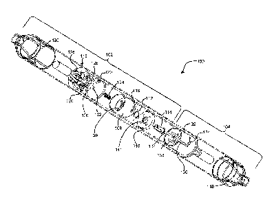
[0005]
Figure 1 is an isometric view of an exemplary embodiment of a electrical
connector
consistent with implementations described herein;
- la-
CA 02707798 2010-06-18
[0006] Figure 2 is a cross-sectional view of the connector of Fig. 1 in a
connected
configuration;
[0007] Figure 3 is an enlarged, cross-sectional isometric view of the first
housing and contact
assembly of Fig. 1;
[0008] Figs. 4A-4E are cross-sectional diagrams illustrating exemplary
implementations of
the connector of Fig. 1;
[0009] Figs. 5A-5C are cross-sectional diagrams illustrating additional
exemplary
implementations of the connector of Fig. 1;
[0010] Figures 6A-6D are isometric illustrations of the connector of Fig. 1
in various stages
of connection; and
[0011] Figures 7A and 7B are isometric illustrations of the exemplary
connector of Fig. 1 in
various stages of disconnection.
DETAILED DESCRIPTION OF THE PREFERRED EMBODIMENTS
[0012] The following detailed description refers to the accompanying
drawings. The same
reference numbers in different drawings may identify the same or similar
elements.
[0013] Consistent with implementations described herein, an electrical
connector may be
provided that minimizes deleterious effects associated with high voltage
implementations and/or
hazardous environment conditions. For example, in one implementation, an
electrical connector
may include a male connector and a female connector, with the male connector
configured for
insertion into the female connector. The female connector may include an
access assembly
configured to prevent unintentional or undesired access to a contact assembly
of the female
connector. During connection, conductors in the male connector first bypass a
dead front and
- 2 -
CA 02707798 2010-06-18
proceed axially along the female connector to the contact assembly without
electrically
contacting the conductors in the contact assembly.
[0014] In one implementation, the connector may be placed into a first
connected position in
which the male connector is securely attached to the female connector, but
with the conductors
of the male connector not electrically coupled to the female connector. This
may be referred to
as the connected ¨ OFF position. Additional movement of the female connector
and the male
connector may bring the conductors into electrical contact and may place the
connector into a
second connected position, referred to as the connected ¨ ON position.
[0015] Figure 1 is an exploded isometric diagram illustrating an exemplary
electrical
connector 100 consistent with embodiments described herein. Figure 2 is a
cross-section
diagram of connector 100 taken in an axial direction. As illustrated,
electrical connector 100
may include a female connector 102 and a male connector 104. Female connector
102 may
further include a first housing portion 106, an intermediate housing portion
108, a dead front
110, a dead front spring 112, a dead front pin 114, first notched slots 116, a
contact assembly
118, guide pins 120, a center contact sleeve 122, spring 124, cup-connectors
126, contacts 128,
and female cover 130. Male connector 104 may include a second housing portion
132, second
notched slots 134, a center connector pin 136, connector pins 138, and a male
cover 140.
[0016] As described briefly above, high voltage electrical connectors may
be implemented in
a variety of environments and applications. Furthermore, arcing or flashover
of electricity
between the contacts on the male and female sides of the connector may be
possible prior to
seated contact between the male and female contacts, due to the high voltages.
In environments
in which flammable or combustion sustaining gases (e.g., a mixture of a
explosive gas and
oxygen, for example) are present, such flashovers may result in catastrophic
damage to
- 3 -
CA 02707798 2010-06-18
personnel, equipment, and/or property. In the manner described in detail
below, connector 100
may include a configuration that provides an insulating and reduced
atmospheric environment
between male and female contacts at the time of contact connection.
[0017] As illustrated in Fig. 1, male connector 104 may include second
housing 132, center
connector pin 136 and connector pins 138. As described in additional detail
below, center
connector pin 136 may be configured for insertion into a central hole through
the components of
female connector 102. In one implementation, center connector pin 136 may be
configured to
carry ground or common electrical signals/current. Connector pins 138 may be
configured to
carry current or electrical signals, such as current for high voltage
electrical applications.
Connector pins 138, as described more fully below, may be configured for
insertion through
dead front 110, intermediate housing 108, and first housing 106. Furthermore,
following rotation
of male connector 104 relative to female connector 102, connector pins 138 may
be configured
for insertion into cup-connectors 126.
[0018] Second housing 132 of male connector 104 may include notched slots
134 configured
to receive guide pins 120 connected to first housing 106. Travel of guide pins
through notched
slots 134 may guide rotational and axial movement of female connector 102
relative to male
connector 104 in a predetermined manner, as will be described in additional
detail below. Male
cover 140 may be formed over second housing 132 and may form a protective
covering for male
connector 104 as well as approximately one half of an enclosed environment for
connector 100
upon connection to female connector 102.
[0019] Female connector 102, as described above, may include first housing
106,
intermediate housing 108, and dead front 110. In one exemplary implementation,
first housing
106, intermediate housing 108, and dead front 110 may be substantially
cylindrical and may be
- 4 -
CA 02707798 2010-06-18
configured to reside within female cover 130 in a substantially nested manner.
More
specifically, first housing 106 may include a cavity therein for receiving
intermediate housing
108 and dead front 110.
[0020] In one implementation, as shown more clearly in Fig. 2, first
housing 106,
intermediate housing 108, and dead front 110 may be configured such that a
cylindrical gap 200
is provided between an outer diameter of intermediate housing 108/dead front
110 and an inner
diameter of first housing 106 when intermediate housing 108/dead front 110 is
mounted axially
within intermediate housing 106. Gap 200 may be of a width suitable for
receiving second
housing 132 of male connector 104 during connection of connector 100.
[0021] Dead front 110 may be connected axially to intermediate housing 108
via dead front
pin 114. As illustrated, dead front 110 may include a flanged/notched
configuration that engages
a corresponding notched portion of intermediate housing 108 such that rotation
of dead front 110
about dead front pin 114 is enabled within a predetermined range of motion. In
addition,
intermediate housing 108 and dead front 110 may be further configured to
include holes 109 and
111, respectively, corresponding to a spacing of connector pins 138 in male
connector 104.
[0022] In one implementation, dead front 110 may be spring-loaded with
respect to
intermediate housing 108, such that the holes in dead front 110 are not
initially aligned with the
holes in intermediate housing 108. In one exemplary embodiment, a central
portion of
intermediate housing 108 and dead front 110 may be recessed to receive dead
front spring 112.
The biasing force provided by dead front spring 112 may urge dead front 110
into a first position
relative to intermediate housing 108. Rotation of dead front 110 about dead
front pin 114 may
oppose the biasing force of dead front spring 112 and may cause holes 111 in
dead front 110 to
align with holes 109 in intermediate housing 108.
- 5 -
CA 02707798 2010-06-18
=
[0023] Dead front 110 may operate to prevent an unintended or rushed
connection of male
connector 104 to female connector 102 in that a user must first insert
connector pins 138 into
dead front 110, rotate dead front 110 relative to intermediate housing 108
until holes 109 align
with holes 111, and insert connector pins 138 further into intermediate
housing 108.
100241 In one implementation consistent with implementations described
herein, the length
and width of first housing 106, intermediate housing 108, and holes 109 are
configured to allow
potentially combustible or hot gases to vent away from contact assembly 118
during insertion or
removal of connector pins 138 into female connector 102. In other
implementations, holes 109
(and/or holes 111) may be filled with a conductive brush material or other
assembly for
increasing an efficiency of a potential flame path, in the event of an
explosion in connector 100.
Additional details relating to the flame path provided in connector 100 are
described below in
relation to Figs. 4A-4E and 5A-5C.
[0025] First housing 106 may be configured to support or otherwise
connect to contact
assembly 118. Fig. 3 is an enlarged isometric view illustrating first housing
106, contact
assembly 118, center contact sleeve 122, and cup-connectors 126. As
illustrated in Fig. 3, first
housing 106 may be configured to include cavity 300 for receiving intermediate
housing 108
therein, and contact openings 310 and center spring opening 320 therein which
engagingly
support cup-connectors 126 and center spring 124, respectively. Contact
openings 310 may be
further configured to include axial grooves to receive connector pins 138 in a
first non-connected
position. Rotation of connector pins 138 relative to cup-connectors 126 may
cause connector
pins 138 to move within contact openings 310 and engage with cup-connectors
126.
[0026] Consistent with embodiments described herein, center sleeve
opening 320 and contact
openings 310 may be configured to have a minimal volume for containing
environmental air and
- 6 -
I
CA 02707798 2010-06-18
. .
exhaust gases. For example, center sleeve opening 320 may be configured to
closely conform to
an outside diameter of center contact sleeve 122. Similarly, contact openings
310 may be
configured to closely conform in size to cup-connectors 126 and an outside
diameter of
connector pins 138. In one exemplary implementation, a total volume of space
within center
spring opening 320 and contact openings 310 is less than or equal to
approximately 10 milliliters
(m1). By reducing the volume of gas available within connector 310, the
likelihood of an
explosion occurring during arcing or flashover (or the severity of such an
explosion) is
significantly reduced.
[0027] Furthermore, as illustrated in Fig. 3, in one exemplary
implementation, cup-
connectors 126 may be formed of a resilient, conductive material, having a
compressed C-shape
as indicated by pinched portion 330, in which an open end of cup-connectors
126 is slightly
narrower than a width of connector pins 138. The configuration of cup-
connectors 126 may
provide a snap-engagement with connector pins 138 upon rotational engagement
between cup-
connectors 126 and connector pins 138. More specifically, the compressed C-
shape of cup-
connectors 126 allows for a build up of potential energy as connector pins 138
traverse and
slightly deform the "arms" of cup-connectors 126 and travel toward pinched
portion 330 from
within the base of cup connectors 126. Upon reaching the peak of pinched
portion 330, the built
up potential energy may be released by projecting connector pins 138 out of
and away from cup-
connectors 126, thus providing a snap disconnect releasing connector pins 138
from cup-
connectors 126.
[0028] By providing such a snap-engagement between connector pins
138 and cup-
connectors 126, the speed in which a connection may be disengaged (or engaged)
is significantly
- 7 -
CA 02707798 2010-06-18
=
increased over non-snap-engagement implementations. This speed increase
further reduces a
likelihood of arcing or flashover during connection or disconnection of
connector 100.
[0029] Center contact sleeve 122 may be configured to receive center
connector pin 136.
Additionally, spring 124 may be positioned about center contact sleeve 122
within center spring
opening 320, such that the biasing force of spring 124 urges first housing 106
axially away from
intermediate housing 108. As discussed above, the volume of center spring
opening 320 as well
as contact openings 310 may be reduced to minimize the likelihood that an
explosion will occur
or the severity of an explosion in the event of arcing or flashover between
connector pins 138
and cup-connectors 126.
[0030] Contacts 128 may be connected to cup-connectors 126 and
center contact sleeve 122.
Each contact 128 may be further configured to receive wires or leads that
extend through female
cover 130. As illustrated in Fig. 2, male connector 104 may include similar
contacts.
[0031] As illustrated in Fig. 1, first housing 106 may be further
configured to include guide
pins 120. Guide pins 120 may be positioned such that the inwardly extending
ends of guide pins
120 are received within first notched slots 116 in intermediate housing 108.
For example, during
assembly of female connector 102, intermediate housing 108 may be inserted
into first housing
106 prior to insertion of guide pins 120 into corresponding holes in first
housing 106.
[0032] The size and location of first notched slots 116 may be
configured to enable both
rotational and axial movement of intermediate housing 108 relative to first
housing 106 within a
predetermined range of motion. As illustrated in Fig. 1, intermediate housing
108 may be
configured to include a notched slot 116 allowing two stages of rotational
movement, and one
stage of axial movement. Second housing 132 in male connector 104 may be
configured to
include a similar notched slot 134.
- 8 -
CA 02707798 2010-06-18
[0033] As will be described in additional detail with respect to Figs. 4A-
4D, rotational and
axial movement of guide pins 120 within slot 116, as well as corresponding
notched slot 134 in
male connector 104, may facilitate connection of female connector 102 to male
connector 104 in
two distinct positions. In a first position, female connector 102 may be
connected to male
connector 104, but connector pins 138 are not electrically coupled to cup-
connectors 126. This
may be referred to as the connected ¨ OFF position. In a second position,
connector pins 138
may be moved into electrical engagement with cup-connectors 126. This may be
referred to as
the connected ¨ ON position. As briefly discussed above, the shape of cup-
connectors 126 may
effectively secure connector pins 138 within cup-connectors 126 upon movement
of connectors
102 and 104 from the first position to the second position.
[0034] As illustrated in Fig. 2, upon connection of female connector 102 to
male connector
104, second housing 132 may become inserted in the gap formed between
intermediate housing
108 and first housing 106. Connector 100 may be further configured such that
guide pins 120
restrain relative movement between first housing 106, intermediate housing
108, and second
housing 132. Because contact assembly 118 is fixed relative to first housing
106 and connector
pins 138 are fixed relative to second housing 132, rotation between first
housing 106 and second
housing 132 effectively brings connector pins 138 into electrical contact with
cup-connectors
126. However, because electrical contact is only possible following initial
insertion of male
connector 104 into female connector 102 in the first (e.g., non connected)
position, female cover
130 and male cover 140 may form a contained environment sufficient to minimize
an exposure
to potentially volatile environmental conditions prior to electrical contact
or proximity between
connector pins 138 and cup-connectors 126.
- 9 -
CA 02707798 2010-06-18
[0035] As will be discussed below in relation to Figs. 4A-4E and 5A-5C,
interaction of
components within connector 100 may provide a flame path for venting of a
flame or explosion
in the event of an explosion within connector 100. More specifically, elements
of intermediate
housing 108, female cover 130, and/or male cover 140 may be configured to
provide for the
venting or extinguishing of any such flame without destroying connector 100 or
damaging the
surrounding environment or personnel.
[0036] Furthermore, spring 124 may provide an opposing force between guide
pins 120
affixed to first housing 106 and notched slots 116 in intermediate housing
108. This biasing
force may be suitable for preventing or minimizing unintended movement of
guide pins 120
relative to notched slots 116 through the positioning and size of the notches
in notched slots 116.
[0037] Female cover 130 may be formed over first housing 106 and may form a
protective
covering for female connector 104 as well as approximately one half of the
enclosed
environment for connector 100 upon connection to male connector 102. In one
exemplary
implementation, female cover 130 and/or male cover 140 may be formed of a
plastic, rubber, or
elastomeric material that provides both a high friction, easily grippable
surface, in additional to
protective insulative properties. In other implementations, female cover 130
and male cover 140
may include a textured or ridges surface to further enhance secure handling
and connection of
connector 100.
[0038] Figures 4A-4E are cross-sectional diagrams illustrating exemplary
implementations
of the connector 100. In Fig. 4A, an explosion or spark 400 at an interface
between connector
pin 138 and cup-connector 126 may travel along a flame path 410 provided for
in connector 100.
As shown, flame path 400 may include interfacing surfaces between first
housing 106 and
intermediate housing 108 CI, interfacing surfaces between second housing 132
and first housing
- 10 -
I
CA 02707798 2010-06-18
. ..
106 0, and interfacing surfaces between first housing 106 and male cover 140
0. As
illustrated, an explosion or spark may travel along flame path 410 and may
vent from connector
100 at the interface between male cover 140 and female cover 130. By providing
an exhaustible
flame path for enabling the release of explosive energy or flames from
connector 100, connector
100 may be capable of operating safely in hazardous environments.
[0039] Fig. 4B illustrates another exemplary implementation of the
interface between male
cover 140, female cover 130, and first housing 106. As illustrated in Fig. 4B,
a gap 415 may be
provided between male cover 140 and female cover 130. Gap 415 may be suitably
sized to
efficiently enable release of explosive energy or flames from flame path 410
in the event of
arcing or flashover within connector 100, as described above in relation to
Fig. 4A.
[0040] Figs. 4C and 4D illustrates another exemplary
implementation of the interface
between male cover 140, female cover 130, and first housing 106. As
illustrated in Figs. 4C and
4D, a male cover 140 may be provided with a hinged portion 420 or flap
proximate to the
interface with female cover 130. As illustrated in Fig. 4D, in the event of an
explosion or flame
within flame path 410, hinged portion 420 may open or deform to allow the
explosive energy,
flames, and/or hot gases to exhaust from connector 100. Although Figs. 4C and
4D depict
hinged portion 420 as being part of male cover 140, hinged portion may also be
provided in
female cover 140, or in both male cover 140 and female cover 130.
[0041] Fig. 4E illustrates yet another exemplary implementation of
the interface between
male cover 140, female cover 130, and first housing 106. As illustrated in
Fig. 4E, male cover
140 and female cover 130 may be configured to overlap. For example, male cover
140 may be
provided with an enlarged portion 425 configured to receive female cover 130
in an overlapping
manner. In some implementations, female cover 130 may be configured to
interlock with
- 11 -
1
1
CA 02707798 2010-06-18
enlarged portion 425 to further secure female connector 102 to male connector
104 during
connection.
[0042] In the event of an explosion or flame within flame path 410, flame
path 410 may
continue along the interface between enlarged portion 420 and female connector
130 to allow the
explosive energy, flames, and/or hot gases to exhaust from connector 100.
Enlarged portion 425
may be suitably sized to efficiently enable release of explosive energy or
flames from flame path
410 in the event of arcing or flashover within connector 100.
[0043] Figs 5A-5C are cross-sectional diagrams illustrating additional
exemplary
implementations of connector 100. As illustrated in Fig. 5A, intermediate
housing 108 may
include one or more expansion chambers 500 for receiving explosive energy
resulting from an
explosion or spark experienced at an interface between connector pin 138 and
cup-connector.
For example, each interface between a connector pin 138 and a cup-connector
126 may be
connected to a respective expansion chamber 500, e.g., via conductor opening
310. In one
implementation, as illustrated in Figs. 5A-5C, expansion chambers 500 may
include a resilient
and/or compressible material 510 configured to compress and absorb explosive
energy in the
event of an explosion or spark. Compression of material 510 also opens up a
volume of
expansions chamber 500 thereby allowing explosive energy to dissipate.
[0044] As illustrated in Fig. 5A, in an initial, uncompressed state,
material 510 substantially
fills a volume of each expansion chamber 500. However, as illustrated in Fig.
5B, an explosive
event 520, such as an arcing or flashover event, may cause explosive energy or
flames to travel
from connector opening 310 into expansion chambers 500.
[0045] As illustrated in Fig. 5B, the explosive energy may cause a
compression of material
510 within expansion chambers 500, to ameliorate or dissipate the explosive
energy in expansion
-12-
CA 02707798 2010-06-18
chambers 500. Upon dissipation of the explosive energy, material 510 may
decompress and
refill expansion chambers 500, as illustrated in Fig. 5C.
[0046] By providing an expansion chamber having a compressible material
there, the
embodiment of Figs. 5A-5C may prevent or minimize damage to connector 100
and/or the
surrounding environment resulting from explosive events.
[0047] Figures 6A-6D are isometric illustrations of an exemplary connector
100 in various
stages of connection. In Fig. 6A, female connector 102 is being brought into
initial contact with
male connector 104. In Fig. 6B, connector pins 138 have been inserted through
dead front 110
and dead front 110 has been rotated relative to intermediate housing 108 to
align holes 109 in
intermediate housing 108 with holes 111 in dead front 110.
[0048] In Fig. 6C, connector pins 138, center connector pin 136, and second
housing 132 has
been fully inserted into female connector 102. More specifically, connector
pins 138 may be
received into contact openings 310 in the first position, as described above,
center connector pin
136 may be received into center contact sleeve 122, and second housing 132 may
be received
into the gap formed between intermediate housing 108 and first housing 106.
[0049] Moreover, when connector pins 138 are inserted through intermediate
housing 108,
guide pins 120 become aligned with an exposed opening in second notched slots
134 in second
housing 132. Guide pins 120 may travel axially along notched slots 134 until
they reach the first
notch in notched slots 134. Following axial insertion, rotation of female
connector 102 relative
to male connector 104 may place guide pins 120 into the first position in
notched slots 134 and
(not shown in Fig. 6C) notched slots 116.
[0050] As described above, the biasing force created by compression of
spring 124 between
intermediate housing 108 and first housing 106 causes guide pins 120 to remain
in the first
- 13 -
CA 02707798 2010-06-18
position in notched slots 116 and 134, rather than travel further axially
along notched slots 116
and 134. In this position, a gap remains between female cover 130 and male
cover 140 for
enabling gases contained within connector 100 to be vented prior to connector
100 being placed
into the second position.
100511 Fig. 6C represents connector 100 in the first connected position, in
which female
connector 102 is securely attached to male connector 104, but connector pins
138 are not in close
electrical proximity with cup-connectors 126.
[0052] Fig. 6D illustrates connector 100 in the second connected position,
in which female
connector 102 is securely attached to male connector 104 and connector pins
138 are electrically
connected to cup-connectors 126. To enter the second position, female
connector 102 is initially
moved axially toward male connector 104. This axial movement causes guide pins
120 to travel
along notched slots 134 and 116 and also causes female cover 130 to come into
contact with
male cover 140, effectively sealing the environment in which the electric
connection is made.
Female connector 102 is then moved rotationally with respect to male connector
104. Upon this
rotational movement, connector pins 138 may move within contact openings 310
(shown in Fig.
3) and into electrical contact with cup-connectors 126. As described briefly
above, the shape of
cup-connectors 126 may cause male connector 104 to snap connect with female
connector 102,
such that the electrical contact between connector pins 138 and cup-connectors
126 is secure.
Axial and rotational movement of female connector 102 relative to male
connector 104 is
represented by directional arrows in Figs. 6B-6D.
100531 Because transition from the first connected position to the second
connected position
can only occur following full insertion of male connector 104 into female
connector 102,
exposure to outside environmental conditions is minimized or reduced by the
interrelation of the
- 14 -
CA 02707798 2010-06-18
components of connector 100, as illustrated in Fig. 2, thus reducing the
likelihood of an
explosive accident in the event of arcing or flashover.
[0054] Figures 7A and 7B are isometric illustrations of an exemplary
connector 100 in
various stages of disconnection. In Fig. 7A, female connector 102 is moved
rotationally with
respect to male connector 104 in a direction opposite to the connection
direction as referenced by
the directional arrow in Fig. 7A. In one exemplary embodiment, the snap
connection created
between cup-connectors 126 and connector pins 138 may be disengaged by
rotating the female
connector 102 relative to the male connector 104 with a predetermined amount
of torque. As
described above, the C-shape and resilient nature of cup-connectors 126 may
cause potential
energy to build up as connector pins 138 move out of engagement with cup
connectors 126. The
potential energy may be released when connector pins 138 pass the narrowest
portion of cup-
connectors 126, thereby projecting or snap releasing connector pins 138 from
cup connectors
126.
[0055] Continued rotational movement of female connector 102 relative to
male connector
104 causes guide pins 120 to travel along notched slots 116 and 134 until they
reach an end of
the second notch. The biasing force created by spring 124 then causes female
connector 102 to
move axially away from male connector 104 and back to the first connected
position.
[0056] As illustrated in Fig. 7B, female connector 102 is again moved
rotationally with
respect to male connector 104, causing guide pins 120 to travel along notched
slots 116 and 134
until they reach an end of the first notch. Female connector 102 may then be
axially removed
from male connector 104, thereby freeing guide pins 120 from notched slot 134.
Although not
explicitly illustrated in Fig. 7B, removal of connector pins 138 from female
connector 102 allows
dead front 110 to snap back to its resting position, by virtue of dead front
spring 112. In this
- 15-
CA 02707798 2010-06-18
position, the holes in dead front 110 (e.g., holes 111 in Fig. 1) are no
longer axially aligned with
the holes in intermediate housing 108 (e.g., holes 109 in Fig. 1). In this
manner, a user may
break electrical contact within connector 100 prior to releasing mechanical
attachment between
female connector 102 and male connector 104. This may help to prevent
electrical current
flashover when connector 100 is detached from a live circuit.
[0057] The foregoing description of exemplary implementations provides
illustration and
description, but is not intended to be exhaustive or to limit the embodiments
described herein to
the precise form disclosed. Modifications and variations are possible in light
of the above
teachings or may be acquired from practice of the embodiments.
[0058] For example, various features have been mainly described above with
respect to a
electrical connectors having four contact pins and a ground pin. In other
implementations, any
suitable number of contact pins may be used, depending on the type of
connector being designed
or equipment being used. In some implementations, connector consistent with
the above
description may be used in various environments and systems, such as,
indoor/outdoor lighting
systems, conveyors and light motors, assembly plants, processing plants, pulp
and paper
facilities, sawmills, steel foundries, etc. In addition, the above-described
connector may be used
in hazardous environments, such as oil refineries, gas processing plants, gas
pipelines, chemical
manufacturing facilities, etc.
[0059] Although the invention has been described in detail above, it is
expressly understood
that it will be apparent to persons skilled in the relevant art that the
invention may be modified
without departing from the spirit of the invention. Various changes of form,
design, or
arrangement may be made to the invention without departing from the spirit and
scope of the
- 16 -
CA 02707798 2010-06-18
invention. Therefore, the above-mentioned description is to be considered
exemplary, rather
than limiting, and the true scope of the invention is that defined in the
following claims.
[0060] No element, act, or instruction used in the description of the
present application
should be construed as critical or essential to the invention unless
explicitly described as such.
Also, as used herein, the article "a" is intended to include one or more
items. Where only one
item is intended, the term "one" or similar language is used. Further, the
phrase "based on" is
intended to mean "based, at least in part, on" unless explicitly stated
otherwise.
-17-