Note: Descriptions are shown in the official language in which they were submitted.
CA 02707973 2010-06-03
WO 2009/089322 PCT/US2009/030399
TIP FOR AN EARTH WORKING ROLL
Field of the Invention
[01] The present invention pertains to a tip for an earth-working roll such as
used in a roll crusher, surface miner, underground mining machines, milling
machine
and the like.
Background of the Invention
[02] A number of machines involved in mining, construction and public
works use rolls that are driven for the crushing, mining, milling and the like
of
earthen materials. These earth working rolls include an array of tips to
engage the
material to be worked. The tips are releasably secured to holders attached to
the roll
at various locations. The tips are wear parts that are replaced after a
certain length
of use.
[03] As one example, earth working tips can be provided in a roll crusher
for the crushing of earthen material in a mining operation. In a typical
operation (Fig.
53), the mined material I is dumped into a chute 3 and directed onto a
conveyor 5
for transport to a roll crusher 7. The roll crusher 7 is a double roll
crusher, which
includes a pair of opposed rolls 9 to break up the mined material 1. Each roll
9 is
fitted with an array of tips 11 adapted to engage the mined material and break
it up
(Fig. 54). The tips are secured to holders 13 that are fixed to the rolls 9.
The rolls 9
are rotated in opposite directions so that the tips 11 are driven toward each
other
from the top. The broken material 1A passing through the roll crusher 7 is
deposited
on a second conveyor 17 for transport to rotary screens 19 for separation of
the
material.
1
CA 02707973 2010-06-03
WO 2009/089322 PCT/US2009/030399
[04] Tip 11 is a one-piece member that includes a mounting shaft 21 for
attachment to a holder 13, and a cone 23 for engaging the mined material I
(Figs.
55-57). Cone 23 has a conical exterior 25 with a rounded front end 27
corresponding to a generally spherical segment. The driving of the cone
through the
material in a conventional tip 11 imposes a substantial drag on the rotation
of the
roll as the earthen material drags along a full one half of the cone's large
periphery.
The use of many cones on a roll multiplies the drag such that high power
requirement are needed to drive the rolls.
[05] Mounting shaft 21 has a stepped configuration for a. mating fit into a
hole in holder 13, and a securing groove 31 into which the free end of a screw
threaded into the holder is received to permit rotation of the cone during
use. On
account of the shape of the cones and its intended rotation, hardfacing 29 is
applied
over the entire cone 23. A double layer of hardfacing is applied over the
leading
portion 23A of the cone to extend the usable life of the tip. Hardfacing,
however, is
expensive and adds considerably to the overall cost of the tip.
[06] The tip's shaft and the wall of the hole in the holder receiving the
shaft
are machined and close fitting to provide sufficient support for the tip. Even
so, due
to the invasiveness of earthen fines and the chaotic nature of a crushing or
mining
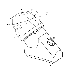
operation, fines commonly get embedded in the hole around the shaft. These
fines
tend to restrict and oftentimes prevent the rotation that is intended for the
tip, thus,
nullifying the potential gain of even wearing. Moreover, the presence of fines
in the
holder around the shaft can make the tip difficult to remove from the holder.
2
CA 02707973 2010-06-03
WO 2009/089322 PCT/US2009/030399
Summary of the Invention
[07] The present invention pertains to an improved tip for use on an earth
working roll for mining, construction and public works machines such as
crushers,
surface miners, underground mining machines, milling machines and the like.
[08] In accordance with one aspect of the invention, the tip comprises two
components secured together by a retainer. One component is a base that is
secured to a holder, and the other component is a wear cap that engages the
earthen material. The wear cap sets over the base and contacts the earthen
material for crushing, mining, etc. As a result, the wear cap wears out well
before
the base. With this construction, only the wear cap needs to be replaced, and
successive wear caps can be mounted onto the same base. This results in less
material being. discarded and an easier change out process.
[09] In accordance with other aspects of the invention, the tip is defined as
a wear cap with a cavity that mounts over a protruding seat defined by the
holder. In
this arrangement, the need for an integral or separate base for the tip is
eliminated.
Since much less material is needed, manufacturing cost and storage
requirements
for the tips are reduced. Moreover, as with the two piece tips, the use of a
tip
formed solely as a wear cap means less material is discarded and the tips can
be
replaced much more easily.
[10] In accordance with another aspect of the invention, at least the front
portion of the tip is provided with side relief to reduce drag and wearing,
require less
power to drive the rolls, and lengthen the usable life of the tip. The side
surfaces
connecting the leading and trailing surfaces of at least the front portion of
the tip are
predominantly within the width of the leading surface. The provision of such
side
3
CA 02707973 2010-06-03
WO 2009/089322 PCT/US2009/030399
relief can reduce wear and drag irrespective of whether the tip is a two piece
tip with
a base and a wear cap, is a tip defined solely by a wear cap, or is a one
piece tip with
a working end and a mounting shaft. In one preferred construction, the front
portion
of the tip has a generally trapezoidal transverse configuration with the
leading
surface being wider then the trailing surface. Nevertheless, side relief could
be
provided with other constructions.
[11]: In another aspect of the invention, the front portion of the tip has
side
relief in its penetration profile for increased reduction in wear and drag.
The
penetration profile is the transverse configuration taken in the general
direction of
the material flow relative to the tip during operation of the machine.
[12] It has been determined that the intensive wearing effects associated
with the operation of a driven roll is experienced primarily on the front end
of the tip
and in the primary direction of the flow of the material relative to the
movement of
the tip. By providing side relief in this portion and in the direction of the
primary flow
of the material, hardfacing need only be provided on this front end without
shortening the useable life of the tips. The use of less hardfacing reduces
costs and
eases manufacturing.
[131 In another aspect of the invention, the tip has a leading surface
inclined upward to the front surface to define a foremost impact corner for
striking
the rock and other earthen material. The intersection of the front and leading
surfaces to define a corner as the foremost leading portion of the tip to
strike the
material provides a high strength construction that is not easily broken.
[141 In another aspect of the invention, the front surface is inclined
rearward from the leading surface in the primary direction of the flow of the
material
4
CA 02707973 2010-06-03
WO 2009/089322 PCT/US2009/030399
relative to the tip. Arranging the front surface at such an angle reduces the
wear
experienced by the tip and provides for even wearing of the tip.
[15] In another aspect of the invention, the tip is attached to the holder to
restrict rotation of the tip about its longitudinal axis. This arrangement
simplifies the
mounting assembly and enables the use of more varied mounting constructions.
[16] In another aspect of the invention, the renewing of worn tips in an
earth working machine having a driven roll can be accomplished easily and
quickly.
In a method in accordance with the present invention a retainer holding a wear
cap
of each worn tip that needs to be renewed is released. Each wear cap is
removed
from a seat that is secured to the roll. A new wear cap is installed onto each
seat
where a wear cap was removed. Each installed wear cap is then secured to the
seat
with a retainer.
Brief Description of the Drawings
[17] Figures 1 and 2 are each a perspective view of a: tip in accordance
with the present invention mounted in a holder.
[18] Figure 3 is a sectional view of the tip mounted in a holder.
[19] Figure 4 is a side view of the tip mounted in a holder in operation in a
double roll crusher.
[20] Figure 5 is a side view the tip.
[21] Figure 6 is a cross sectional view taken along line 6-6 in Figure 5.
[22] Figure 7 is a cross sectional view taken along line 7-7 in Figure 5.
[23] Figure 8 is a top view of the tip.
[24] Figure 9 is a bottom view of the tip.
[25] Figure 10 is a front view of the tip.
CA 02707973 2010-06-03
WO 2009/089322 PCT/US2009/030399
[26] Figure 11 is a perspective view of the tip.
[27] Figure 12 is an exploded perspective view of the tip.
[28] Figure 13 is a perspective view of the tip in an inverted position.
[29] Figure 14 is an exploded perspective view of the tip in an inverted
position.
[30] Figures 15 and 16 are each a perspective view of a base of the tip.
[31] Figure 17 is a perspective view of the base in an inverted position.
[32] Figure 18 is a side view of the base.
[33] Figure 19 is a top view of the base.
[34] Figure 20 is a bottom view of the base.
[35] Figure 21 is a front view of the base.
[36] Figure 22 is a rear view of the base.
[37] Figures 23 and 24 are each a perspective view of a wear cap of the tip.
[38] Figure 25 is a perspective view of the wear cap in an inverted position.
[39] Figure 26 is a. side view of the wear cap.
[40] Figure 27 is a top view of the wear cap.
[41] Figure 28 is a bottom view of the wear cap.
[42] Figure 29 is a rear view of the wear cap.
[43] Figure 30 is a front view of the wear cap.
[44] Figure 31 is a cross sectional view taken along line 31-31 in Figure 30
with a screw in exploded view.
[45] Figure 32 is a perspective view of a retainer for the tip.
[46] Figure 33 is an exploded perspective view of the retainer.
[47] Figure 34 is an exploded side view of the retainer.
6
CA 02707973 2010-06-03
WO 2009/089322 PCT/US2009/030399
[48] Figure 35 is an exploded top view of the retainer.
[49] Figure 36 is a front view of the retainer.
[50] Figure 37 is a rear view of the retainer.
[51] Figure 38 is a sectional view of the retainer.
[52] Figure 39 is a perspective view of an alternative holder.
[53] Figure 40 is a side view of the alternative holder.
[54] Figure 41 is a top view of the alternative holder.
[55] Figure 42 is a perspective view of a second alternative holder and an
alternative wear cap.
[56] Figure 43 is an exploded, perspective view of the second alternative
holder and alternative wear cap.
[57] Figure 44 is a perspective view of the alternative wear cap.
[58] Figure 45 is a perspective view of the second alternative holder.
[59] Figure 46 is a perspective view of another alternative tip in
accordance with the present invention.
[60] Figure 47 is a side view of the alternative tip of Figure 46.
[61] Figure 48 is a top view of the alternative tip of Figure 46.
[62] Figure 49 is a front view of the alternative tip of Figure 46.
[63] Figure 50 is a partial perspective view of a scroll crusher with tips in
accordance with the present invention.
[64] Figure 51 is an end view of the two rollers in the scroll crusher.
[65] Figure 52 is a perspective view of a tip in accordance with the present
invention in a holder for the scroll crusher.
7
CA 02707973 2010-06-03
WO 2009/089322 PCT/US2009/030399
[66] Figure 53 is a schematic illustration of a mining operation with a
double roll crusher.
[67] Figure 54 is a schematic illustration of the operation of the rolls in a
double roll crusher.
[68] Figure 55 is a perspective view of a conventional tip.
[69] Figure 56 is a side view of the conventional tip.
[70] Figure 57 is a cross sectional view of the conventional tip taken along
line 57-57 in Figure 56.
Detailed Description of the Preferred Embodiments
[71] The present invention pertains to tips for an earth working roll or
roller
such as used in roll crushers, surface miners, milling machines and the like.
The tips
are at times described in this application in relative terms such as upper,
lower, front,
rear, vertical, horizontal and the like. These relative directional terms are
not
essential to the invention. The orientations of the tips on an earth working
roll
change considerably during operation. Accordingly, the use of these relative
terms Is
not to be limiting of the invention, but rather to ease the description. Also,
the tips in
this application are described primarily in the context of a double roll
crusher.
Nevertheless, the invention is not limited to this operation. Tips in
accordance with
the invention are also suitable for use in conjunction with other earth
working
machines involving the use of driven rolls with tips such as single roll
crushers, scroll
crushers, surface miners, underground mining machines, milling machines and
the
like.
[72] In one embodiment of the invention (Figs. 1-38), tip 35 is a two piece
tip including a base 37 and a wear cap 40. Base 37 includes a mounting shaft
42
8
CA 02707973 2010-06-03
WO 2009/089322 PCT/US2009/030399
and a seat 44 for wear cap 40. The wear cap sets over the seat to engage the
material to be worked, e.g., the mined material I fed into a double roll
crusher 7.
Wear cap 40 is a wear part that is releasably secured to base 37 by a retainer
46.
[73] The shaft 42 of base 37 is shaped for mating receipt within a. hole 48
in holder 13 (Fig. 3). In this example, shaft 42 generally has a stepped,
cylindrical
configuration with a hole or depression 51 near its rear end== 53 (Figs. 11-
20); though
other configurations could be used. The hole 51 could extend entirely through
shaft
42 but preferably only extends partially through the shaft. A mounting screw
55 is
threaded through a bore 57 in holder 13 so that its free end 59 is receivable
into
depression 51 to contact the shaft 42 and retain the tip in the holder (Fig.
3). Since
depression 51 is closed on its longitudinal sides 58 (i.e., sides extending
generally in
a longitudinal direction), the receipt of screw into it prevents rotation of
tip 35 about
its longitudinal axis 60 during use. Other means could be used to secure tip
35 to
holder 13 and other kinds of holders could be used. For example, a mounting
screw
placed at a different location or orientation could be used. A non threaded
retainer
such as a block or pin with a retaining latch, a pin with other retaining
means, keyed
element, etc. could also be used. Also, the hole could have a different shape
than
shown. It is simply necessary to securely hold the tip to the roll with
sufficient
support to withstand the expected loads. In embodiments including side relief,
rotation of the tip is prohibited. In other embodiments, rotation of the tip
could be
permitted if desired.
[74] Seat 44 of base 37 sets atop the holder to receive and mount a wear
cap 40 (Figs. 11-22). Seat 44 preferably has a generally rounded exterior
surface
62 that tapers toward front face 64, and a rear surface 65 adapted to bear
against
9
CA 02707973 2010-06-03
WO 2009/089322 PCT/US2009/030399
holder 13. Front face 64 is preferably flat and generally perpendicular to
axis 60,
but could have other shapes or orientations. Grooves 66 are preferably
provided on
opposite sides to receive rails 68 of wear cap 40 to prevent rotation of the
wear cap
about axis 60. Grooves 66 preferably extend entirely through seat 44 to
maximize
the retention force, but could have only a partial extension if desired. The
marginal
edges 69 of each groove 66 are oriented transverse to longitudinal axis 60,
and are
preferably inclined outward for easier manufacture and receipt of rails 68.
Nevertheless, marginal edges 69 could also be horizontal. The grooves could be
placed in different locations, though on opposite sides is preferred to
provide
maximum resistance to loads applied perpendicular to the longitudinal axis,
i.e., in
the direction of the movement of the tip when the roll is driven. The grooves
could
be curved or have other shapes. There could also be only one groove or more
than
two grooves. Finally, other structural arrangements could be used to prevent
rotation of the wear cap and/or provide resistance to transverse loading of
the tip.
[75] Seat 44 also preferably includes stabilizing surfaces 70 to provide
stable support for wear cap 40. Stabilizing surfaces 70 are vertically aligned
(i.e.,
aligned generally in the direction the tip is moved as the roll rotates) and
extending
rearward from front face 64. Stabilizing surfaces 70 are substantially
parallel to axis
60.. The term "substantially parallel" includes surfaces that are parallel to
axis 60 as
well as those that are at a small angle a to axis 60, e.g., of about 1-7
degrees. The
stabilizing surface preferably diverges rearward at a small angle to axis 60
for ease
of manufacturing. Stabilizing. surfaces 70 are preferably each at an angle to
axis 60
of less than 5 degrees, and most preferably 2-3 degrees. The stabilizing
surface 70
provides enhanced support for the wear cap 40 against impact and other applied
CA 02707973 2010-06-03
WO 2009/089322 PCT/US2009/030399
forces during use. Struts 72 preferably extend to front face 64 between
stabilizing
surface 70 and grooves 66 for additional strength. A hole 74 is preferably
formed in
the lower stabilizing surface 70 for receipt of retainer 46, but other
arrangements
and other positions could be provided to cooperate with retainer 46.
[76] Wear cap 40 includes a cavity 78 that opens or faces rearward to
receive seat 44, and a wear surface 81 that faces generally forward for
engaging
material I (Figs. 1-14 and 23-31). Cavity 78 corresponds to the configuration
of
seat 44. In the illustrated embodiment, cavity 78 is generally closed around
its
perimeter, but in other embodiments, the cavity may be open along one or more
of
its sides. The seat and cavity could have a wide variety of constructions so
long as
they provide sufficient support for the wear cap. The entire seat is
preferably
received into wear cap 40 to protect it from the earthen material and
premature
wear. Alternatively, the base could define the cavity and the wear cap the
protruding
seat.
[77] In this embodiment, cavity 78 has a generally rounded configuration,
particularly in the rear portion, to matingly receive the rounded exterior
surface 62 of
seat 44, and a front surface 84 that bears against front face 64. A pair of
inwardly
projecting rails 68 extends axially along opposite sides of cavity 78 for
receipt within
grooves 66. The sidewalls 87 of each rail 68 are shaped to match the shape of
marginal edges 69. The receipt of rails 68 in grooves 66 resists rotation of
wear cap
40 about axis 60 during use. Rails 68 also provide vertical support against
loads
applied to the wear cap (i.e., loads applied in the general direction the tip
moves or
in the opposite direction). Alternatively, rails could be provided on the seat
and
11
CA 02707973 2010-06-03
WO 2009/089322 PCT/US2009/030399
grooves on the cavity in the wear cap. Other arrangements for preventing
rotation of
the wear cap could also be used in lieu of or in addition to the rails and
grooves.
[78] Cavity 78 further includes upper and lower supports 89 with stabilizing
surfaces 95 that fit within recesses 96 of seat 44 so that stabilizing
surfaces 95
contact and bear against the complementary stabilizing surfaces 70.
Stabilizing
surfaces 95, like stabilizing. surfaces 70, are substantially parallel to the
longitudinal
axis 60. While stabilizing surfaces 70, 95 are preferably flat, they could be
curved or
have other configurations. Moreover, as an alternative, stabilizing surfaces
70, 95
could have a greater inclination to axis 60 and not be substantially parallel
to axis 60
for certain applications, for example, those in: lighter duty applications.
Also, in
certain applications, the wear cap and seat could each include only one
stabilizing
surface in engagement with each other to resist loading in one primary
direction.
Further, arrangements other than such stabilizing surfaces could be used to
support
the mounting of the wear cap on the base. An opening 97 is provided through
the
lower support 89 to align with hole 74 in base 37 when the wear cap is mounted
on
the base for receipt of retainer 46.
[79] Wear surface 81 has a front portion 98 that makes initial and primary
contact with material I and, in a roll crusher 7, is primarily responsible for
breaking
up the material. The front portion 98 includes a front surface 100 facing.
generally
forward or outward from the holder, a leading surface 101 facing generally in
the
direction the tip moves with the roll, a trailing surface 102 opposite the
leading
surface, and side surfaces 103 extending between the leading. and trailing
surfaces
101, 102. The front portion 98 is preferably formed with side relief to reduce
wear
and drag on the tip so that the usable life of the tip is lengthened and less
power is
12
CA 02707973 2010-06-03
WO 2009/089322 PCT/US2009/030399
needed to drive the roll. Side relief is provided by forming the side surfaces
103 to
be predominantly within the width or lateral sides 105 of the leading surface
101.
[80). In this embodiment, side surfaces 103 are generally planar and
inclined inward from the leading surface 101, i.e., the side surfaces 103
generally
converge toward each other as they extend to trailing surface 102. This
arrangement provides a front portion 98 for wear cap 40 that has a generally
trapezoidal transverse configuration. In this embodiment, portions of the
leading
surface 101 are wider than the opposite, corresponding portions of the
trailing
surface 102; the corresponding portions of the two surfaces 101, 102 being
those
that are opposite each other in a direction perpendicular to the longitudinal
axis 60.
This inward inclination enables side surfaces 103 to be protected by leading
surface
101. and experience reduced pressure from and contact with the earthen
material 1;
see the general flow F of material 1 relative to the front portion 98 in
Figures 5, 7
and 15. Reduced pressure and contact translates into reduced wearing of the
tips
and lessened drag on the rolls being rotated. It has been determined that the
primary contact with material 1 and wearing of the tips occurs along the front
end of
the tips. Side relief, then, is preferably provided only along front portion
98. In this
way, rear portion 109 expands to accommodate an expanded rear portion of seat
44
for strength of the seat and a stable support against holder 13. Nevertheless,
side
relief could extend through most or the entire wear cap. The front end of seat
44
also preferably has a generally trapezoidal shape to better accommodate the
exterior
side relief in wear cap 40.
[81] The side surfaces 103 are each preferably inclined inward at a
transverse angle 0 so that they are within the width W of leading surface 101
(Fig. 6).
13
CA 02707973 2010-06-03
WO 2009/089322 PCT/US2009/030399
In this way, side surfaces 103 travel in the shadow of leading surface 101
passing
through material I so that they experience less wear and drag. In one
preferred
construction, the transverse angle 6 is sufficiently great so that the side
surfaces
103 of front portion 98 are inclined inward in the penetration profile for the
wear cap
40 (Fig. 7). The penetration profile is the cross-sectional configuration of
the tip
taken in the primary direction of the flow of the earthen material 1 relative
to the tip.
For example, in a double roll crusher 7, the earthen material tends to flow
relative to
the tips at an inclination to the longitudinal axis 60 of the tips 35 (Fig.
5). In
conventional tips, this relative movement causes wear to develop in cone 23 at
this
inclination to the longitudinal axis 60, particularly when fines prohibit
rotation of the
tip. In one exemplary double roll crusher 7, the flow of material 1 relative
to the tip is
at an angle of about 70 degrees to the longitudinal axis 60. The penetration
profile
for tips in this machine would then be along a transverse plane at an angle of
about
70 degrees relative to axis 60. By providing side relief in the penetration
profile, side
surfaces 103 remain inward of the leading surface 101 with respect to the
primary
flow of the material relative to the tips. This arrangement provides enhanced
protection for the tip and further reductions in the drag on the roll.
[82] In one preferred example, side surfaces 103 are inclined to define a
transverse angle 6 of about 15 degrees (Fig. 6) so as to provide about a 5
degree
angle A in the penetration profile (Fig. 7). As can be appreciated, a 15
degree
transverse angle 0 results in the side surfaces converging toward each other
with an
included angle of about 30 degrees. Nevertheless, side surfaces 103 may be
inclined at other transverse angles and still provide some benefits of side
relief.
While inclining each side surface 103 in the penetration profile at an angle A
of at
14
CA 02707973 2010-06-03
WO 2009/089322 PCT/US2009/030399
least 5 degrees is preferred, smaller angles will still result in reduced wear
and drag.
Also, side surfaces 103 that are predominately within the width of the leading
surface 101, but which are not inclined inward in the penetration profile will
still
provide reduced wear and drag as compared to tips with no side relief.
Although
side relief is preferably only provided in front portion 98, it could be
extended into
rear portion 109 as well.
[83] Front surface 100 of wear cap 40 is preferably inclined to axis 60 at
an angle that is generally parallel to the direction of the relative flow of
material 1 to
tip 35. Accordingly, front surface 100 is preferably inclined at an angle cp
of about
70 degrees to longitudinal axis 60 for a double roll crusher. Nevertheless,
other
angular orientations could be used. Although a planar front surface 100 is
preferred,
the front surface could alternatively have a slight concave or convex
curvature.
Moreover, the front end could have other shapes including a blunt, rounded
front
end, a sharp digging point, or other configurations. The front surface may
optionally
be formed of carbide or another hard material or have hard inserts of carbide,
ceramic or other hard material.
[84] Leading surface 101 is preferably inclined forwardly and upwardly
relative to axis 60 so that the foremost portion of wear cap 40 is an impact
corner
110 to strike rock and other earthen material needing to be broken up. The
formation of a corner to primarily impact rock and the like is a strong
construction
that is not easily broken. Leading surface 101 preferably has a front segment
101'
and rear segment 101 though it could have a uniform configuration rearward of
front surface 100. In a preferred construction, front segment 101' extends
rearwardly from front surface 100 at an angle a of about 30 degrees to axis 60
to
CA 02707973 2010-06-03
WO 2009/089322 PCT/US2009/030399
form impact corner 110. Rear segment 101" is preferably inclined at a smaller
angle relative to axis 60 to offer some shielding of retainer 46. Trailing
surface 102
preferably extends rearward from front surface 100 at an angle R of about 15
degrees to axis 60. Nevertheless, other orientations are possible.
[85] Wear caps in accordance with the invention can have shapes other
than illustrated. The side surfaces can be placed at different angles to the
leading
surface. The side surfaces need not be planar and can be, e.g., curved,
angular or
irregular. Side relief benefits can still be obtained even if the side
surfaces extend
laterally beyond the width of the leading surface so long as the side surfaces
are
predominantly within the width of the leading surface; though confining the
side
surfaces entirely within the width of the leading surface is preferred. In
addition, the
leading, trailing and front surfaces can also be formed with non-planar
shapes. In a
front portion that is formed with curved surfaces, particularly a curved
leading
surface, there may be no clear delineation between the side surfaces and the
leading surface. Side relief in accordance with the present invention could be
provided in such instances if the side walls are positioned within the largest
lateral
width of the leading surface for more than half of the transverse distance
between
the foremost leading portion and the rearmost trailing portion of that portion
of the
tip provided with side relief (i.e., the distance between the leading and
trailing
surfaces and perpendicular to the longitudinal axis 60), and preferably more
than
about 75% of the distance.
[86] Due the harsh environment during use, it is preferable to provide wear
cap 40 with hardfacing. However, it has been determined that the most sever
wearing occurs at the front of the tips and along a direction that is inclined
to the
16
CA 02707973 2010-06-03
WO 2009/089322 PCT/US2009/030399
longitudinal axis 60 of the tip. As a result, hardfacing need only be provided
on the
front portion 98 of wear cap 40 with its rear edge 106 along an inclination
generally
parallel to the primary direction of the flow of the material relative to the
tip (Figs. 1,
and 26). In one preferred construction, the hardfacing is applied in an even
band
at an angle of about 70 degrees to axis 60, which is preferably parallel to
front
surface 100. This limited use of hardfacing decreases the cost of the tip
without any
significant decrease in the useful life of the tip as compared to tips 11 with
hardfacing over the entire cone 23.
[87] Retainer 46 preferably includes a screw or male threaded member
111 and a nut or female threaded member 113 (Figs. 3, 12, 14 and 31-38),
though
other kinds of retainers (with or without threads) could be used. Screw 111
has a
threaded shaft 115 with a free end 117, and a head 119 with tool engaging
means
opposite free end 117. Nut 113 includes a threaded bore 121 and a pair of flat
outer sides 123 to fit against flat sidewalls 99 in opening 97 to prevent
rotation of
the nut, though other non-circular shapes could be used. The nut is inserted
into
opening 97 from cavity 78. The nut can be retained in opening 97 by a flange
on its
inner end, by an interference fit with opening 97, by a corresponding
narrowing of
the nut and the opening, or other means. The use of such a nut enables opening
97
to be cast or otherwise formed without threads. Nonetheless, opening 97 could
be
formed with threads as an alternative. The threaded shaft 115 of screw 111 is
threaded through bore 121 for receipt into hole 74 to hold wear cap 40 to seat
44.
[88] In a preferred embodiment, nut 113 further includes a resilient
member 133 to contact screw 111 and resist unwanted loosening. during use. The
resilient member is preferably a sleeve 133 that surrounds shaft 115. Sleeve
133
17
CA 02707973 2010-06-03
WO 2009/089322 PCT/US2009/030399
includes a flange 139 that fits around a reduced portion 141 of nut 113 to
couple
the sleeve 133 and nut together. Sleeve 133 could alternatively be initially
secured
to screw 111 by adhesive, molding or other means. In the illustrated example,
sleeve 133 includes a rim 135 that snaps into a groove 137 adjacent head 119
as
screw 111 is fed through bore 121, though other arrangements are possible.
Sleeve
133 resists unwanted loosening of screw 111 during use, but permits retraction
of
screw 111 when turned with a tool such as a torque wrench.. Other arrangements
could be used to resist loosening such as lock nuts, etc. Sleeve 133 also
works to
sea[ opening 97 to lessen the embedding of fines among the threads of screw
111
and nut 113 and thereby ease the release of the lock. Sleeve 133 is preferably
formed of a polymer such as urethane, but could have other compositions as
well.
[89] Nut 113 is preferably fitted in wear cap 40 during manufacture, but
could be assembled by the operator. Likewise, screw 111 is also preferably
attached to the wear cap (i.e., by threading into nut 113) so that the
retainer 46 is
integrally connected to the wear cap during manufacture as well. In this way,
the
proper fitting of nut 113 in opening 97 and sleeve 133 to screw 111 can be
assured.
Moreover, in this way, retainer 46 always remains a part of the wear cap 40 so
that
there is no need to store and keep track of a separate lock. The wear cap can
be
installed on the base with screw 111 in nut 113 provided free end 117 does not
project into cavity 78, though screw 111 could be removed if desired. Once
wear
cap 40 is fully seated on seat 44, screw 111 is advanced so that free end 117
is
received in hole 74 in base 37. Preferably, free end 117 does not press
against the
bottom surface 125 of hole 74, but it could be made to do so. Rather, head 119
preferably includes a peripheral flange 127 that is received into a counter
bore 129
18
CA 02707973 2010-06-03
WO 2009/089322 PCT/US2009/030399
in opening 97 to stop advancement of screw 1i1 past this point. A larger
counter
bore 131 is also provided in wear cap 40 to permit a tool to engage head 119.
Of
course, other shapes and arrangements for nut 113, screw 111 and opening 97
could be used.
[90] A wear indicator 143 preferably formed as a cavity extension forward
of cavity 78 is provided to identify when the wear cap is spent and should be
replaced (Figs. 3 and 31). When wear cap 40 is to be replaced, screw 111 is
retracted or removed so that free end 117 is moved out of hole 74. Wear cap 40
can then be pulled from seat 44. If embedded fines cause wear cap 40 to stick
to
seat 44, wear cap 40 can be pried forward from seat 44 with a standard pry
tool (not
shown). However, since there is ordinarily no need to pull the base 37 from
holder
13 (i.e., unless it was also worn and needing to be replaced), the replacement
process is much quicker and easier as compared to conventional tips.
Additionally,
one or more depressions 145 are preferably provided at the rear end of seat 44
to
accommodate the insertion of the pry tool between base 37 and holder 13 to
facilitate removal of the base from the holder when the holder needs to be
replaced.
[91] In an alternative embodiment, the tip is defined by a wear cap 40
alone, i.e., without a base received into the holder. In this embodiment,
holder 13A
includes a seat 44A upon which wear cap 40 is attached (Figs. 39-41). Seat 44A
preferably has the same construction as seat 44 on base 37 though other
arrangements could be used. Preferably, wear cap 40 and retainer 46 have the
same construction as when used with base 37. The only difference is that base
37
is eliminated and seat 44A is integral with holder 13A.
19
CA 02707973 2010-06-03
WO 2009/089322 PCT/US2009/030399
[92] Nevertheless, other holders and wear caps could be used. As one
other example, an alternative embodiment is illustrated in Figures 42-45. In
this
embodiment, holder 13B includes a seat 44B that is defined by a generally I
shaped
formation having a central stem 45B, upper and lower supports 476, 49B, and
side
recesses 52B. Upper support 47B is preferably a flange that extends laterally
from
each side of stem 45B. Lower support 49B is preferably formed as a bearing
surface of the holder base 54B. A hole 74B extends into or through stem 45B
for
receiving a retainer 46B to hold a wear cap 40B to holder 13B.
[93] Wear cap 40B includes a rearward facing or opening cavity 78B for
receiving seat 44B. In this embodiment, cavity 78B has a generally T shaped
configuration in transverse section. A pair of arms 56B extends rearward from
working end 58B to define side rails 61B that fit into recesses 52B on seat
44B.
Each rail 61B is spaced from an upper wall 63B to define an upper groove 67B
adapted to receive upper support 47B. A front surface 84B of cavity 78B is
adapted
to abut front face 64B of seat 448. The upper and lower surfaces 69B, 71B of
arms
56B are adapted to bear against the upper and lower supports 47B, 49B,
respectively. Upper surface 69B is preferably inclined downward relative to
the
longitudinal axis to keep a low profile with holder 13B. A hole 73B extends
through
one or each arm 56B and generally aligns with hole 74B in holder 138 for
receiving
retainer 46B.
[94] Once wear cap 40B is mounted on seat 44B, a retainer 46B is
inserted to hold the wear cap to the seat. Retainer 46B is preferably of the
same
design as retainer 46 but could have other constructions.
CA 02707973 2010-06-03
WO 2009/089322 PCT/US2009/030399
[95] In another embodiment of the invention (Figs. 46-49), tip 150 is a one-
piece member that includes a front working end or portion 152 to engage the
earthen material 1, and a rear mounting end or portion 154 to secure the tip
to a roll
via a mount or base. Tip 150 preferably has essentially the same exterior
configuration except for the features related to retainer 46. The working end
152 of
tip 150 has a front surface 160, a leading surface 162, a trailing surface 164
and a
pair of side surfaces 166 extending between surfaces 162, 164. The working end
152 has the same exterior configuration as wear cap 40. Mounting end 154 has
the
same configuration as shaft 42. Accordingly, the working end is preferably
formed
with side relief along front portion 198 to reduce wear and drag on the tip so
that the
usable life of the tip is lengthened and less power is needed to drive the
roll. As with
wear cap 40, side relief is provided by forming the side surfaces 166 to be
predominantly within the width or lateral sides of the leading surface 162.
[96] Although preferred embodiments are described above for a two piece
tip, a one piece wear cap tip, and a one piece tip with a working end and a
mounting
end, other arrangements in accordance with the invention are possible.
Different
aspects of the invention can be used in isolation to achieve some of the
benefits of
the invention. For example, a wide variety of different configurations could
be used
to form the cavity, the seat, the external wear surface, or the retainer and
still
achieve the benefits of discarding less material when the working end is worn
out
and provide an easier tip replacement process. The wear cap could even have a
cone shaped exterior and part of a tip that is subject to rotation as with the
cone of a
conventional tip. Further, the front surface of the tip could be curved,
pointed or
have shapes and/or orientations other than planar and inclined to the
longitudinal:
21
CA 02707973 2010-06-03
WO 2009/089322 PCT/US2009/030399
axis. The working end of the tip may also be provided with a carbide or hard
material
front surface, or with embedded carbide, ceramic or other wear resistant
members,
or with other wear resistant means besides hardfacing.
[97) Although the application primarily discloses the use of tips in
accordance with the present invention in conjunction with a double roll
crusher, such
tips could be used in other machines including, for example a scroll crusher
170
(Figs. 50-52). In a scroll crusher operation, tips 35 are attached to holders
13B that
are secured to rolls 9B.
22