Note: Descriptions are shown in the official language in which they were submitted.
CA 02709630 2013-06-13
1
Filter press
The invention relates to a filter press with a press frame to support filter
plates movably along the longitudinal axis of the press frame, where the
filter plates are oriented at right angles to the longitudinal axis of the
press
frame and connected to one another, and where a pressure plate is
provided that can be moved along the longitudinal axis of the press frame
by means of pushing or pulling equipment and which presses the filter
plates against one another during the filtration process.
Filter presses of this kind are used to separate solids from the liquid phase
of a suspension to be filtered. This filtration process takes place in the
filter plates, where several filter plates are joined to one another to form a
filter plate assembly. With the aid of a closing cylinder, usually a hydraulic
closing cylinder, pressure is applied to the filter plate assembly in order to
guarantee the necessary leak-tightness between the individual filter plates.
Each of the filter plates has a filter area covered with a filter cloth, where
the suspension to be filtered is pressed into the filter chamber formed
between two filter plates and against the filter cloth. The filtrate between
the filter cloth and the filter area is then carried off, and the filter cake
remains in the filter chamber. The filter cake drops out when the filter
plates are separated from one another.
In some applications, for example in mining, the cycle times are very short,
which means that closing of the filter plate assembly, filling with the
suspension to be filtered, the filtration process itself, opening of the
filter
plate assembly, discharge of the filter cake, and washing of the filter cloths
all have to proceed relatively quickly, often within a few minutes. A
delaying factor here is opening and closing of the filter plate assembly. In
order to accelerate this process, the filter plates are connected to one
another using chains, for example, so that the entire filter plate assembly
CA 02709630 2013-06-13
2
is pulled apart when the outermost filter plate is moved and the entire filter
cake can drop out. Compared with moving one filter plate after another,
this method requires a longer filter plate travel path. According to the state
of the art, the closing cylinder, for example, is also used to pull the filter
plate assembly apart, however this entails some disadvantages. If the
closing cylinder is used, for example, the press volume is limited because
only one limited cylinder stroke can be realized. A long cylinder stroke
also necessitates large quantities of oil and exposes large areas of the
closing cylinder piston rod to contamination from falling filter cake. In
addition, there are also disadvantages from radial forces and other
unfavourable loads on the piston rod, the piston, and the respective
seals. Lastly, opening and closing the filter plate assembly using the
closing cylinder takes considerable time because the closing cylinder is
designed for high closing pressure, but not for rapid piston movement.
Thus, attempts were also made to provide additional hydraulic drives for
opening and closing the filter plate assembly and which were designed for
a long and rapid cylinder stroke. The correspondingly thin piston rods,
however, cause problems due to their low mechanical loading capacity,
and it is often necessary to use several additional hydraulic drives of this
kind, which have to be controlled exactly however, in order to ensure
synchronous movement. Ultimately, these systems also do not solve the
problem of long piston rods and their being contaminated by falling filter
cake.
An aim of the invention is thus to avoid these disadvantages and to
realize a filter press that provides the necessary closing pressure for the
filter plate assembly on the one hand, but also permits rapid opening and
closing of the filter plate assembly on the other hand. In addition, the
filter
press according to the invention should offer improved protection against
CA 02709630 2013-06-13
=
3
contamination of mechanical components like the closing cylinder, or of
equipment for opening and closing the filter plate assembly.
These objectives are achieved by the characteristic features as described
herein. The invention provides a filter press with press frame containing side
beams to support filter plates movably along the longitudinal axis of the
side beams, where the filter plates are oriented at right angles to the
longitudinal axis of the side beams and connected to one another, and
where a pressure plate is provided that can be moved along the
longitudinal axis of the side beams by means of a pushing or pulling
device, and which presses the filter plates against one another during the
filtration process. The invention suggests that the pushing or pulling
device is mounted on a sliding carriage that can be moved on the side
beams along the longitudinal axis of the side beams by means of a drive
unit mounted on the sliding carriage. When the filter plates are in place,
the filter plate closest to the pressure plate can be connected to the
pressure plate, and thus the filter plates can be moved farther apart or
closer together by moving the sliding carriage. Due to the feature of the
separate sliding carriage, the kinematic process of pressing the filter
plates together by means of the pushing and pulling device is uncoupled
from the process of opening and closing the filter plate assembly. Since
the drive unit is mounted on the sliding carriage, contamination of
mechanical components, such as the pushing or pulling device, or of the
drive unit itself, is avoided.
According to an aspect of the invention, there is provided filter press with
press frame containing side beams to support filter plates movably along
the longitudinal axis of the side beams, where the filter plates are oriented
at right angles to the longitudinal axis of the side beams and connected to
one another, and where a pressure plate is provided that can be moved
along the longitudinal axis of the side beams by means of a pushing or
pulling device, and which presses the filter plates against one another
during the filtration process, characterised by the pushing or pulling device
CA 02709630 2013-06-13
3a
being mounted on a sliding carriage that can be moved on the side beams
along the longitudinal axis of the side beams by means of a drive unit
mounted on the sliding carriage.
The drive unit can have various designs. Further aspects of the invention
provide
that the drive unit comprises at least one gear wheel, which meshes with a
toothed rack mounted on the side beams. This provides a simple
mechanical solution for the drive unit and also permits high speeds by the
sliding carriage. If the teeth of the toothed rack are facing downwards,
CA 02709630 2013-06-13
4
this orientation of the toothed rack can reduce contamination of the rack
and pinion gear caused by falling filter cake.
A further aspect of the invention provides for the pushing or pulling device
to have a hydraulic drive with a hydraulic cylinder, where both the
hydraulic drive and the hydraulic cylinder are mounted on the sliding
carriage. Thus, supply facilities for the pushing or pulling device, such as
hydraulic supply lines, can be kept short.
According to another aspect of the invention, there can be provided the
filter press as described herein, characterised by the drive unit comprising
at least one gear wheel that meshes with at least one toothed rack
mounted on the side beams.
According to a further aspect of the invention, there can be provided the
filter press as described herein, characterised by the teeth of the toothed
rack facing downward.
According to a further aspect of the invention, there can be provided the
filter press as described herein, characterised by the pushing or pulling
device having a hydraulic drive with a hydraulic cylinder, where both the
hydraulic drive and the hydraulic cylinder are mounted on the sliding
carriage.
A further aspect of the invention provides for the sliding carriage to
have at least one interlocking cylinder that interacts with a recess in the
press frame in the vicinity of the closed filter plate assembly. The at least
one interlocking cylinder thus supports the sliding carriage at the side
beams of the press frame when the pushing or pulling device moves the
pressure plate in order to press the filter plates against one another. A
limit stop that ensures exact positioning of the sliding carriage can be
provided here in the vicinity of the closed filter plate assembly in order to
align the interlocking cylinder with recesses in the side beams.
CA 02709630 2013-06-13
4a
According to a further aspect of the invention, there can be provided the
filter press as described herein, characterised by the sliding carriage
having at least one interlocking cylinder that interacts with a recess in the
side beams in the vicinity of the closed filter plate assembly.
According to a further aspect of the invention, there can be provided the
filter press as described herein, characterised by a limit stop being
provided in the vicinity of the closed filter plate assembly.
A further aspect of the invention provides for recesses in the side beams,
where
the sliding carriage has lateral press rolls that roll along the side of the
side beams
facing away from the sliding carriage. The lateral press rolls thus prevent
the side beams from being bent outwards when the interlocking cylinders
are extended. As a supplement, additional press rolls can also be
provided that roll along the side of the beams facing the sliding carriage in
order to prevent the side beams from being bent inwards when the
interlocking cylinder is retracted.
According to a further aspect of the invention, there can be provided the
filter press as described herein, characterised by the sliding carriage
having lateral press rolls that roll along the side of the side beams facing
away from the sliding carriage.
A further aspect of the invention provides that proximity switches be
mounted at a starting position of the sliding carriage in the vicinity of the
closed filter plate assembly and in a final position of the sliding carriage
when the filter plate assembly is open. The proximity switches detect the
position of the sliding carriage and control acceleration and braking
thereof. As a result, movement of the sliding carriage can be optimized.
CA 02709630 2015-08-17
According to a further aspect of the invention, there can be provided the
filter press as described herein, characterised by proximity switches being
mounted in a starting position of the sliding carriage when the filter plate
assembly is open and in a final position of the sliding carriage in the
5 vicinity of the closed filter plate assembly.
According to an aspect of the invention, there is provided a filter press with
a press frame containing side beams to support filter plates movably along
a longitudinal axis of the side beams, where the filter plates are oriented at
right angles to the longitudinal axis of the side beams and said filter plates
are connected to one another, and where a pressure plate is provided that
can be moved along the longitudinal axis of the side beams by means of a
pushing or pulling device, and said pressure plate presses the filter plates
against one another during a filtration process, wherein the pushing or
pulling device is mounted on a sliding carriage that can be moved on the
side beams along the longitudinal axis of the side beams by means of a
drive unit mounted on the sliding carriage.
According to another aspect of the invention, there is provided a filter
press with a press frame containing side beams to support filter plates
movably along a longitudinal axis of said side beams, where said filter
plates are oriented at right angles to the longitudinal axis of said side
beams and said filter plates are connected to one another, and where a
pressure plate is provided that can be moved along the longitudinal axis of
said side beams by means of a pushing or pulling device, and said
pressure plate presses said filter plates against one another during the
filtration process, wherein the pushing or pulling device is mounted on a
sliding carriage that can be moved on said side beams along the
longitudinal axis of said side beams by means of a drive unit mounted on
said sliding carriage, and said pushing or pulling device has a hydraulic
drive for driving a hydraulic cylinder, where both the hydraulic drive and
the hydraulic cylinder are mounted on said sliding carriage.
CA 02709630 2015-08-17
5a
According to a further aspect of the invention, there is provided a filter
press, comprising:
a press frame including side beams;
a plurality of filter plates movably supported along a longitudinal
axis of said side beams, said filter plates being oriented substantially
perpendicularly to said longitudinal axis of said side beams and said filter
plates being connected to one another;
a sliding carriage movable on said side beams along said
longitudinal axis of said side beams;
a first drive assembly including a hydraulic drive for driving a
hydraulic cylinder, said hydraulic drive and said hydraulic cylinder being
mounted on said sliding carriage;
a second drive assembly mounted on said sliding carriage for
moving said sliding carriage, said second drive assembly including at least
one gear wheel meshing with at least one toothed rack mounted on said
side beams; and
a pressure plate movable along said longitudinal axis of said side
beams by said first drive assembly, said pressure plate pressing said
plurality of filter plates against one another during a filtration process.
The invention will now be described in more detail on the basis of an
embodiment example with the aid of the attached drawings. Here,
Fig. 1 shows a perspective view of an embodiment of a filter press
according to the invention without the filter plates mounted,
Fig. 2 shows a perspective view of the sliding carriage, as seen from the
side facing away from the pressure plate,
Fig. 3 shows a side view of the sliding carriage,
Fig. 4 shows a side view of the embodiment of a filter press according to
the invention as shown in Fig. 1, during the filtration process,
CA 02709630 2015-08-17
5h
Fig. 5 shows a side view of the embodiment of a filter press according to
the invention, as shown in Fig. 1, during rapid emptying, and
Fig. 6 shows the embodiment of a filter press according to the invention,
as shown in Fig. 1 , seen from above (without filter plates).
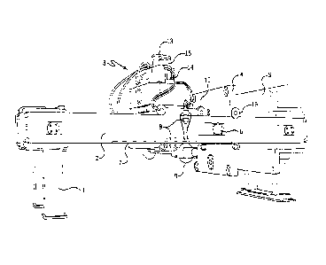
Figure 1 shows a perspective view of an embodiment of a filter press
according to the invention, with a press frame containing end columns 1,
side beams 2, as well as a header 5 at the end of the side beams 2, where
the header 5 serves in particular to absorb the pressing and tensile forces
occurring during manipulation of the filter plate assembly 18. In addition,
there is a pressure plate 4 mounted in a movable support running along
the longitudinal axis of the side beams 2 with the aid of supporting
CA 02709630 2013-06-13
6
rollers 16. The filter plate assembly 18, which is not shown in Figs. 1 ¨ 3
and in Fig. 6, is located between the pressure plate 4 and the header 5.
The supply lines required for filtration in order to feed in the suspension to
be filtered and carry away the filtrate are laid through the header 5.
According to the invention there is also a sliding carriage 3 on the side
beams 2, which is carried on guide rollers 10. The sliding carriage 3 can
be moved along the longitudinal axis of the side beams 2 with the aid of a
drive unit mounted on the sliding carriage 3. In the present embodiment,
the drive unit comprises at least one gear wheel 9 that meshes with at
least one toothed rack 7 mounted on the side beams 2 (see also Fig. 3,
Fig. 4 and Fig. 5). The gear wheel 9 is activated via a hydraulic motor 14,
for example, which is also mounted on the sliding carriage 3. With this
simple arrangement, the sliding carriage 3 can travel at high speeds.
On the sliding carriage 3 there is also a pushing and pulling device,
formed in the present case by a hydraulic closing cylinder 11 and a
hydraulic drive 13. The corresponding hydraulic drive 13 is also mounted
on the sliding carriage 3, with the result that the supply lines can be kept
very short. This reduces the risk of leaks and avoids long lines being laid
from external hydraulic drives. Figure 1 also shows a hydraulic motor 15
including a first motor for large quantities of oil and correspondingly lower
pressure, as well as a second motor for smaller quantities of oil and
greater pressure. The first motor is used for interlocking, as will be
described in more detail, and for lower closing pressure of the closing
cylinder, and the second motor is used to build up high closing pressure by
the closing cylinder, as is required during filtration.
In the side beams 2, recesses 6 are provided close to the closed filter
plate assembly that interact with the pistons of the interlocking
cylinders 12 mounted on both sides of the sliding carriage 3 (see also
CA 02709630 2015-08-17
7
Fig. 2). The interlocking cylinders 12 are activated via an interlocking
hydraulic system and support the sliding carriage 3 at the side beams 2 of
the press frame when the pushing or pulling device moves the pressure
plate 4 in order to press the filter plates 17 against one another. The
recesses 6 can be designed as bronze bushes, for example, that are
inserted into the side beams 2.
In addition, a limit stop can be provided in the vicinity of the closed filter
plate assembly 18 (not shown in Figs. 1 ¨ 6) to ensure exact positioning of
the sliding carriage 3 in order to align the interlocking cylinder 12
correctly
with the recesses 6 in the side beams 2. The piston rods of the
interlocking cylinders 12 can thus mesh exactly with the recesses 6.
Furthermore, the sliding carriage 3 can be provided with lateral press
rolls 8 that roll along the side of the side beams 2 facing away from the
sliding carriage in order to cause the side beams 2 to bend outwards when
the interlocking cylinders 12 are extended.
Movement of the sliding carriage 3 can also be optimized with the aid of
proximity switches. Here, the proximity switches are arranged at a starting
position of the sliding carriage 3 in the vicinity of the open filter plate
assembly 18 and in a final position of the sliding carriage 3 when the filter
plate assembly 18 is closed, and they cause the sliding carriage 3 to brake
and accelerate, respectively, when the sliding carriage 3 is detected.
The filter press according to the invention now functions as follows:
The sliding carriage 3 is located first of all in an outer position farthest
away from the header 5 ¨ the starting position ¨ and emits a control signal
to accelerate the sliding carriage 3 via the hydraulic motor 14. The sliding
carriage 3 now moves towards the header 5 and closes the filter plate
assembly 18 as it does so. Finally, a proximity switch detects the position
CA 02709630 2010-06-16
=
5306-PCT 8
of the sliding carriage 3 in an inner position close to the header 5 ¨ the
final position ¨ and emits a control signal to brake the sliding carriage 3
via
the hydraulic motor 14.
The sliding carriage 3 is positioned precisely in its final position using a
limit stop. A control signal to the interlocking hydraulics subsequently
causes the piston rods of the interlocking cylinders 12 to extend in such a
way that their piston rods mesh into the recesses 6. A further control
signal to the hydraulic drive 13 activates extension of the piston of the
hydraulic cylinder 11 in order to apply closing pressure to the closed filter
plate assembly 18 via a pressure plate 4 (Fig. 4). The filter plate
assembly 18 is now ready for filtration. During filtration the filtrate is
drained off through pipes that run through the header 5, and a filter cake
builds up between the filter plates 17 that has later to be removed.
In order to remove the filter cake upon completion of filtration, the filter
plate assembly 18 must then be pulled apart. For this purpose, a control
signal to the hydraulic drive 13 first causes the piston of the hydraulic
cylinder 11 to retract and thus reduce the closing pressure on the filter
plate assembly 18. The stroke length here is short, in the range of
500 mm, thus this process does not take long. A further control signal to
the interlocking hydraulics then causes the piston rods of the interlocking
cylinders 12 to retract, thus leaving the recesses 6 empty. A
corresponding control signal to the hydraulic motor 14 activates the drive
unit of the sliding carriage 3 such that the sliding carriage 3 is removed
from the header 5 by means of the gear wheels 9 and the toothed rack 7.
The outermost filter plate 17 of the filter plate assembly 18 facing the
pressure plate 4 is connected to the pressure plate 4, and all other filter
plates 17 are connected to this outermost filter plate 17, for example by
chains. Thus, the movement of the sliding carriage 3 causes the filter
plates 17 in the filter plate assembly 18 to be pulled apart from one
CA 02709630 2010-06-16
5306-PCT 9
another, and the filter cake drops to the floor under the force of gravity
(Fig. 5, Fig. 6).
Finally, a further proximity switch detects the position of the sliding
carriage 3 in its outermost position farthest away from the header 5 ¨ the
original starting position ¨ and emits a control signal to brake the sliding
carriage 3 via the hydraulic motor '14. When the sliding carriage 3 has
come to a standstill and the filter cake has dropped to the floor, the filter
press according to the invention is ready for a new cycle.
The filter press according to the invention thus provides the necessary
closing pressure for the filter plate assembly 18 on the one hand, but also
allows the filter plate assembly 18 to be opened and closed rapidly on the
other hand. In addition, the arrangement of the hydraulic drive 13 and the
hydraulic cylinder 11, of the interlocking hydraulics 15 for the interlocking
cylinders 12, and of the hydraulic motor 14 protects them against
contamination. Furthermore, the main supply lines for the hydraulic units
can be kept short.