Note: Descriptions are shown in the official language in which they were submitted.
CA 02709756 2010-06-17
WO 2009/077922 PCT/1B2008/055168
A BRUSHHEAD/HANDLE INTERFACE FOR A POWER TOOTHBRUSH
This invention relates generally to handle/brushhead interface arrangements
for power toothbrushes, and more specifically concerns such an interface in
which the
torque transfer function and axial retention function of the brushhead
relative to the
toothbrush driveshaft is accomplished by a single spring and coupling
combination.
Many power toothbrushes have a structural arrangement in which a
driveshaft, driven rotationally or through a selected angle of oscillation,
extends from a
handle portion of the toothbrush, with the drive mechanism being contained
within the
handle portion. A removable brushhead assembly fits onto the extending
driveshaft. The
brushhead assembly includes a coupling member, which fits into an arm portion
of the
brushhead assembly. At the distal end of the arm portion is a brush member for
cleaning
teeth. The driveshaft extends into and securely mates with the coupling
member.
The structural interaction between the drive shaft and the coupling member
must be such as to reliably transfer the torque of the moving driveshaft to
the brushhead
and to maintain the torque transfer under load. The load refers to a
combination of the
torque created by the inertial mass of the oscillating brushhead and the
forces created by
the interaction with the tissues and other elements of the user's mouth. The
structural
interaction must also be sufficient to hold the brushhead on the driveshaft,
which is
referred to as axial retention, during operation of the toothbrush, while also
permitting the
brushhead to be conveniently removed by the user. Axial retention can be a
challenging
aspect of such an arrangement if the brushhead is to be removed regularly for
cleaning or
other purposes. The arrangement must be such that the functions of torque
transfer and
axial retention are not degraded even after the brushhead assembly has been
removed
numerous, perhaps hundreds, of times during the lifetime of the brushhead
assembly.
The present arrangement is capable of reliably providing both the torque
transfer and the axial retention functions, while permitting a large number of
removals of
the brushhead assembly from the driveshaft.
CA 02709756 2014-11-10
64869-1404
2
The disclosed arrangement is a brushhead/handle interface for a power
toothbrush, comprising: a brushhead assembly having a brush member at one end
thereof for
cleaning teeth; a driveshaft extending from a handle portion of the
toothbrush, driven such
that it oscillates through a selected rotational angle, the driveshaft having
one or more contact
regions in which are located interface surfaces; a coupling member positioned
at the other end
of the brushhead assembly for receiving the driveshaft, wherein the coupling
member includes
one or more interface portions which come into physical contact with said
interface surfaces
of the driveshaft when the driveshaft is inserted into the coupling member;
and a spring
member positioned so as to exert a force against the coupling member large
enough that the
physical contact between said interface portion or portions of the coupling
member and said
one or more contact regions of the driveshaft is sufficient to produce a
reliable torque transfer
between the drive shaft and the brushhead assembly and to maintain axial
retention of the
brushhead assembly on the driveshaft during operation of the toothbrush, while
permitting a
user to remove the brushhead assembly from the driveshaft when the toothbrush
is not
operating.
According to an aspect there is provided a brushhead/handle interface for a
power toothbrush, comprising: a brushhead assembly having a brush member at
one end
thereof for cleaning teeth; a driveshaft extending from a handle portion of
the toothbrush,
driven such that it oscillates through a selected rotational angle, the
driveshaft having one or
more contact regions in which are located interface surfaces; a coupling
member positioned at
the other end of the brushhead assembly and having a body with an internal
axial opening for
receiving the driveshaft, wherein the coupling member includes one or more
interface portions
which come into physical contact with said interface surfaces of the
driveshaft when the
driveshaft is inserted into the coupling member; and a spring member
positioned around a part
of the body portion so as to exert a force against the coupling member large
enough that the
physical contact between said interface portion or portions of the coupling
member and said
one or more contact regions of the driveshaft is sufficient to produce a
reliable torque transfer
between the driveshaft and the brushhead assembly and to maintain axial
retention of the
brushhead assembly on the driveshaft during operation of the toothbrush, while
permitting a
CA 02709756 2014-11-10
64869-1404
2a
user to remove the brushhead assembly from the driveshaft when the toothbrush
is not
operating.
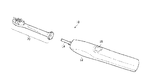
Figure 1 is a partially exploded view of a toothbrush described herein
comprising a handle portion and a brushhead assembly portion.
Figure 2 is an exploded view of the brushhead assembly portion of Figure 1.
Figures 3A and 3B are isometric views of the coupling member shown in
Figure 2.
Figure 4 is an isometric view of a spring member portion of the brushhead
assembly of Figure 2.
1 0 Figure 5 is a cross-sectional view of the coupling member of
Figure 2.
Figure 6 is an isometric view of a driveshaft with a first contact surface
embodiment.
Figure 7 is an elevational view of a driveshaft with another contact surface
embodiment.
1 5 Figure 8 is a side elevational view of the driveshaft of Figure 6.
Figure 9 is a simplified cross-sectional view of the handle/brushhead assembly
interface of Figures 5, 6 and 8.
CA 02709756 2010-06-17
WO 2009/077922 PCT/1B2008/055168
3
Figures 10A-10C are simplified cross-sectional views of three variations of
another embodiment of the brushhead assembly/handle interface.
Figure 11 is a simplified cross-sectional view of another embodiment of the
brushhead assembly/handle interface.
Figures 12A-12C are simplified cross-sectional views of three variations of
another embodiment of the brushhead assembly/handle interface.
Figures 13A-13C are simplified cross-sectional views of three variations of
a still further embodiment of the brushhead assembly/handle interface.
Figure 1 shows a toothbrush 10 which includes a handle portion 12 with a
drive assembly which includes an extending driveshaft 14, the driveshaft
driven by a motor
(not shown) positioned within handle 12. The motor moves the driveshaft in an
oscillating
manner through a selected angle. The motor is controlled by a user-operated
on/off switch
16. Removably mounted on driveshaft 14 is a brushhead assembly 20.
Referring to Figure 2, the brushhead assembly 20 includes a coupling
assembly 22 which fits snugly into and is captured by an arm portion 24 of the
brushhead
assembly. Positioned on a distal end of the arm portion is a conventional
brush member 26
which cleans the teeth. In operation, brush member 26 rotates/oscillates back
and forth
through a selected angle to accomplish the desired cleansing. The coupling
assembly may
further include a ring 28 at the proximal end 30 of the coupling assembly. The
ring can be
different colors to identify the user of the brushhead assembly. The coupling
assembly
further includes a spring member 34 which fits around a portion of the body of
the
coupling assembly 22.
The coupling assembly is shown in more detail in Figures 3A and 3B. It
includes a base portion 36, the lower end of which may be configured to
receive ring 28.
Forward of ring 28 is an inwardly angled surface portion 38, substantially
cone-shaped.
Forwardly of the angled portion 38 is a coupling body portion 40. The body
portion 40
includes an internal axial opening which receives the driveshaft 14. Along one
side of the
body portion 40 is a rib 41 which extends for substantially the length of the
body portion,
the rib fitting snugly into a mating slot in arm portion 24. The rib 41
locates and maintains
the physical relationship between the coupling assembly and the arm portion
24.
CA 02709756 2010-06-17
WO 2009/077922 PCT/1B2008/055168
4
On the opposite side of the body portion from rib 24 is a coupling strip 44.
This is shown in both Figures 3B and Figure 5. In the embodiment shown,
coupling strip
44 is fixedly mounted to the body portion 40 at the opposing ends of the strip
and is free to
flex to some extent between its two ends. The body portion 40 is made from
acetal which
permits flexing of the coupling strip to occur, while being tough enough to
resist abrasion
and compression deformation or creep during the life of the brushhead.
Coupling strip 44
is approximately 0.6 mm long and approximately 0.3 mm wide. It is
approximately 0.80
mm thick, except for a first interface contact member portion 46, which is
approximately
1.323 mm thick. The first interface contact member 46 is a bulge or block
which extends
inwardly from coupling strip 44 approximately 0.16 mm, sufficient to make a
significant
physical contact with the inserted driveshaft 14. Alternatively, the first
interface contact
member could be located on spring member 34, in which case the coupling strip
44 could
be eliminated.
As indicated above, spring member 34 is positioned around a part of the
body portion 40 of the coupling assembly. Spring member 34 is shown in more
detail in
Figure 4. The spring member is, in the embodiment shown, an angled C-shaped
configuration, although it could be other configurations, including an oval or
a closed
arrangement. The spring could also be a leaf spring or a coil spring. Spring
member 34 is
arranged and configured to provide an inwardly directed force against the body
portion of
the coupling assembly with sufficient frictional and physical contact between
the body
portion and the driveshaft to produce the desired torque transfer as well as
axial retention.
In the embodiment shown, this force is in the range of 30-60 newtons,
preferably
approximately 50 newtons. The body portion of the coupling assembly and the
extending
portion of the driveshaft can be of various configurations to achieve this
desired functional
result.
In one embodiment, referring to Figures 6 and 8, a contact portion 49 on the
driveshaft includes a plurality of grooves 50 which extend laterally across
the contact
portion, which is flat. In this embodiment, there are a total of five grooves,
which number
can be varied. The grooves are approximately 0.10 mm deep, have a generally
curved
configuration, with a distance of 0.65 mm center to center. The physical
interaction
CA 02709756 2010-06-17
WO 2009/077922 PCT/1B2008/055168
between the grooves 50 in the first contact portion of the driveshaft and the
first interface
contact member 46 produces a good torque transfer between the driveshaft and
the
brushhead assembly, as well as sufficient axial retention to maintain the
brushhead
assembly on the driveshaft during operation of the toothbrush. The axial
retention is also
5 such as to permit the user to conveniently remove the brushhead from the
driveshaft for
cleaning and the like, without degrading the torque transfer and axial
retention functions.
Figure 7 shows another embodiment of a driveshaft contact portion 55. In
this embodiment, contact portion 55 has been roughened, such as by
sandblasting or the
like. The surface finish is 0.80 meters or rougher, e.g. up to 1.6 meters.
This driveshaft
surface, with the interface contact member 46 of the coupling member described
above, is
also sufficient to accomplish the desired torque transfer and axial retention
functions.
Figure 9 shows a simplified representation of the embodiment of Figures 5,
6 and 8. It includes a grooved driveshaft 64, an interface contact member 66
of a coupling
member and a representation of the spring function at 68. Portions 70-70 refer
generally to
the brushhead assembly arm, in which the coupling assembly is mounted. Portion
69
refers to the part of the coupling member on the opposite side of the
driveshaft from the
interface contact member. In this embodiment, the spring pressure is against
the interface
contact member, which bears directly against the grooves 71 on the driveshaft
64.
Figures 10A-10C show another embodiment in which driveshaft 72 has a
slot in a surface thereof, the slot being sufficiently large to accommodate an
interface
contact member portion of the coupling assembly. Each of the embodiments of
Figures
10A-10C includes a spring function 73. Figure 10A shows a slot 74 in surface
76 of
driveshaft 72 and an interface contact member 77 fitting therein. Figure 10B
shows a slot
80 in surface 81 of the driveshaft opposite from spring function 73 and an
interface contact
member 75 which extends from coupling assembly on the opposite side from
spring
function73 into slot 80. Figure 10C shows a driveshaft 72 with slots 86 and 88
on both
(opposing) sides of the driveshaft, into which are fitted a first interface
contact member 90
on the same side of the driveshaft as spring function 73, and a second
interface contact
member 92 extending from coupling assembly 93 on the opposite side of the
driveshaft
from spring function 73.
CA 02709756 2010-06-17
WO 2009/077922 PCT/1B2008/055168
6
Figure 11 shows a further embodiment, in which a driveshaft 96 includes a
protrusion 98 from surface 99 thereof, on the spring function side of the
driveshaft.
Interface contact member 100 is positioned adjacent to one end 102 of the
driveshaft
protrusion 98.
Figures 12A-12C show additional embodiments in which protrusions are
located on one or both sides of the driveshaft, with the interface contact
members having a
slot into which the protrusions fit. In Figure 12A, driveshaft 104 includes a
protrusion 106
on the spring function side of the driveshaft. Interface contact member 108
includes a slot
110 into which protrusion 106 fits. Figure 12B shows a driveshaft 112 with a
protrusion
114 on the side opposite from the spring function side. Protrusion 114 fits
into a slot 118
in the coupling assembly on the side opposite from the spring function side of
the coupling
assembly. Figure 12C shows a driveshaft 124 having protrusions 126 and 128 on
opposing
sides of the driveshaft. On the spring side of the driveshaft is interface
contact member
130, which has a slot 132 therein to receive protrusion 126, while in the
opposing side of
the coupling assembly is a slot 136 into which fits protrusion 128.
Figures 13A-13C show further embodiments with roughened surfaces on
contact portions of the driveshaft, like that shown in Figure 7. Figure 13A
includes a
driveshaft 140 having a roughened surface region 142 on the spring function
side of the
driveshaft. Interface contact member 144 makes sufficient physical contact
with the
roughened surface 142 to accomplish the desired functions. Figure 13B shows a
driveshaft
146 with a roughened surface region 148 on the side of the driveshaft opposite
from the
spring function. Coupling assembly portion 150 on the opposite side of the
driveshaft
makes the required physical contact with the roughened region 148. Figure 13C
shows a
driveshaft 152 with roughened surface regions 154 and 156 on opposite sides of
the
driveshaft. Interface contact member 160 engages roughened surface region 154,
while the
surface of coupling assembly portion 164 on the opposite side from interface
member 160
engages roughened surface region 156.
CA 02709756 2014-11-10
64869-1404
7
It should be understood that other arrangements/configurations between the
driveshaft and portions of the coupling assembly are possible.
Although a preferred embodiment of the invention has been disclosed here
for the purposes of illustration, it should be understood that various
changes, modifications
and substitutions may be incorporated in the embodiment without departing from
the scope
of the invention, which is defined by the claims which follow.