Note: Descriptions are shown in the official language in which they were submitted.
CA 02710355 2010-07-16
A
SYSTEM AND RELATED METHOD FOR VISUALLY INDICATING
A CONDITION OF A LOCK ON A RAILROAD HOPPER CAR
Field of the Invention Disclosure
[0001] This invention disclosure generally relates to railroad hopper car and,
more particularly,
to a system and related method for indicating the condition of a lock on a
railroad hopper car.
Background
[0002] Conventional railroad hopper cars include a multisided hopper having a
series of
openings provided on an underside of the car. Such railcars are used to
economically transport a
large variety of commodities including corn, sugar, wheat, aggregate, iron
ore, coal and, etc.
which are hereinafter commonly referred to as "material", between distantly
spaced locations.
As will be appreciated, each hopper car serves a particular need in the
railcar industry.
[00031 Although the design of railroad hopper cars can vary considerably
between
manufacturers, the railcar hopper is typically provided with a plurality of
longitudinally spaced
chutes. At a lower end, each chute has a discharge opening through which
material is discharged
or exhausted from the car.
[0004] A mechanism is carried by the hopper in registry with each discharge
opening to control
the discharge of material therefrom. The particular style or type of mechanism
arranged in
operable association with each discharge opening can also vary between
manufacturers and
depends, in part, on the particular material carried by the hopper car.
Generally, each mechanism
includes an element movable between closed and open positions for controlling
the material flow
from the hopper car. In some applications, the element on each mechanism is
operated under the
-1-
CA 02710355 2010-07-16
4
influence of a powered driver to move between closed and open positions. In
other applications,
the element on each mechanism is manually moved between closed and open
positions.
[0005] As the railroad hopper car moves between locations it is continually
subjected to
vibrations and other movements which can cause the element on the discharge
mechanism to
inadvertently move from the closed position toward an open position. Moreover,
in railyards, the
hopper cars are subjected to humping against other railcars during assembly of
a train consist.
These humping actions can also cause the element on the discharge mechanism to
inadvertently
move from a closed position toward the open position. Of course, inadvertent
movement of the
element on the discharge mechanism toward the open position can result in the
loss of a
significant amount of material from the hopper car during transport between
locations.
[0006] Accordingly, most of today's railcars are equipped with some type of
lock arranged in
operable combination with the mechanism used to discharge material from the
hopper car.
Generally, such lock is operable in either a locked condition, wherein said
lock maintains the
element of the discharge mechanism in a closed position whereby inhibiting the
discharge of
material from the car, and an unlocked condition. Moreover, by maintaining the
discharge
element in a closed position, even if the hopper is empty, ensures the movable
element on the
discharge mechanism is kept out of "harms way" as the car is returned for
reloading. When the
lock is arranged in an unlocked condition, the lock permits the element of the
discharge
mechanism to be moved toward an open position whereby permitting the discharge
of material
from the hopper car. Of course, and depending upon the particular
manufacturer, the lock design
can also vary. Typically, however, the lock mechanism includes a member
movable along a
predetermined path of travel as the lock moves between conditions.
-2-
CA 02710355 2010-07-16
7
[0007] As will be appreciated, the condition of the lock on the discharge
mechanism is an
important concern. Mechanical indicators for showing the condition of the
discharge mechanism
lock currently use a form of linkage system. One problem which has been
identified with such
mechanical indicators relates to their reliability. That is, such mechanical
indicators require an
operator to interpret the condition of the lock based on the angular position
of a pointer or the
like relative a set location on the car. If the operator's interpretation is
faulted, the car may be
permitted to move with the discharge mechanism lock being in an unlocked
condition. Another
problem with such mechanical indicators involves their location on the car.
Frequently, such
mechanical indicators are arranged beneath the hopper on the railcar and are
difficult to view
especially remote from the car. Accordingly, an operator is required to view
each lock
independently from a position directly along side of the railcar and proximate
the lock to
accurately determine the condition of the lock. This is a time consuming and
tedious process -
but one which is heretofore required to interpret the condition of the lock.
Of course, at night,
known indicators using a mechanical linkage system are even more difficult to
see and evaluate
the condition of the lock.
[0008] Today's automated technology has lent itself to railroads and the
ability to readily and
easily assess various conditions on a railcar as it moves between locations.
To accomplish these
goals, however, requires more than a purely mechanical linkage system to
provide the
information necessary to evaluate certain conditions on the railcar.
[0009] Thus, there is a continuing need and desire for a system and related
method for enhancing
the ability to quickly and readily access the condition of a lock on a
railroad hopper car.
-3-
CA 02710355 2010-07-16
= I
Summary
[0010] In view of the above, and in accordance with one aspect, there is
provided, in
combination, a railroad car with a hopper from which material can be
discharged, a mechanism
for controlling the discharge of material from the hopper, with the discharge
including an
element movable between closed and open positions, a lock arranged in operable
combination
with the mechanism, with the lock being operable in either a locked condition,
wherein said lock
maintains the element of said mechanism in the closed position whereby
inhibiting discharge of
material from the hopper, and an unlocked condition, wherein the lock permits
the element of the
discharge mechanism to be moved from the closed position toward the open
position whereby
permitting the discharge of material from the hopper, and wherein the lock
includes a member
movable in a predetermined path of travel as the lock moves between
conditions, a system for
visually indicating the condition of the lock. Such visual system includes an
electrically powered
illuminable indicator arranged on a side of the hopper for indicating whether
said lock is in the
locked condition or the unlocked condition and electric circuitry. The
electric circuitry is
connected to the illuminable indicator and includes sensor technology for
monitoring the
condition of the lock and for controlling the operation of the illuminable
indicator as a result of
signals from the sensor technology indicative of the condition of the lock.
[0011] In one form, the discharge mechanism on the railroad car can be
operated by a powered
driver to move the element of the mechanism between positions. In this form,
the electric
circuitry of the indicator system is preferably powered for a preset time
after said the discharge
mechanism is operated by the driver to move the element of the discharge
mechanism. In one
embodiment, the sensor technology includes a senor mounted on the railroad car
for monitoring
-4..
CA 02710355 2010-07-16
movement of the lock member relative to a predetermined position and for
providing a signal to
the illuminable indicator when the lock member moves relative to the
predetermined position.
100121 A solar energy panel is preferably mounted on the railcar to power a
battery connected to
the illuminable indicator and the electric circuit of the indicator system. In
one form, the
illuminable indicator includes a light operable in either of two modes for
indicating whether the
lock is in the locked condition or the unlocked condition. In another form,
the illuminable
indicator includes two lights, with one light emitting illumination when the
lock is in the locked
condition, and with a second light emitting illumination when the lock in an
unlocked condition.
In a preferred form, a first color is emitted by the illuminable indicator
when the one light is
illuminated, and wherein a second color, different from the first color, is
emitted by the
illuminable indicator when the second light is illuminated.
[0013] According to another aspect, there is provided a system mounted on a
railroad hopper car
for providing a visual indication observable by a person located either
proximate to or remote
from the hopper car of a condition of a lock arranged in operable combination
with a mechanism
on the hopper car for controlling discharge of material from the hopper car.
The discharge
mechanism includes an element movable between closed and open positions. The
lock includes
a member movable in a predetermined path of travel as the lock moves between
locked and
unlocked conditions. Such system includes circuitry connected to a power
source and including
a sensor for providing a signal when the lock is in the locked condition,
wherein the element of
the discharge mechanism is maintained in the closed position, and for
producing another signal
when the lock is in the unlocked condition, wherein the movable element of the
discharge
mechanism is permitted to be moved to the open position. An illuminable
indicator is mounted
-5-
CA 02710355 2010-07-16
to a side of the railroad hopper car and is responsive to signals from said
circuitry for displaying
the condition of the lock viewable from a location proximate to or from a
location remote from
the railroad hopper car.
[0014] Preferably, the sensor is mounted on the railroad car for monitoring
movement of the lock
member relative to a predetermined position and for providing a signal to the
illuminable
indicator when the lock member moves relative to the predetermined position.
In one form, the ,
the electrical power source connected to the electrical circuitry includes a
solar energy panel
mounted on the railroad hopper car.
[0015] In one embodiment, the movable element on the discharge mechanism is
moved between
closed and open positions by a powered driver. In this form, the electric
circuitry of the system is
preferably powered for a preset time after the driver of the discharge
mechanism is operated to
move the element of said mechanism. In a preferred embodiment, the system
further includes
logic circuitry for controlling the illuminable indicator to provide a visual
indication of a fault
with either the system, or the lock, or both.
[0016] In one form, the illuminable indicator includes a light operable in
either of two modes for
indicating whether the lock is in the locked condition or the unlocked
condition. In another form,
the illuminable indicator includes two lights, with one light emitting
illumination when the lock
is in the locked condition, and with a second light emitting illumination when
the lock in the
unlocked condition. Preferably, a first color is emitted by the illuminable
indicator when the one
light is illuminated, and wherein a second color, different from the first
color, is emitted by the
illuminable indicator when the second light is illuminated.
[0017] According to another aspect, there is provided a system mounted on a
railroad hopper car
-6-
CA 02710355 2010-07-16
for providing a visual indication observable by a person located either
proximate to or remote
from the hopper car of a condition of a lock arranged in operable combination
with a mechanism
on the hopper car for controlling discharge of material from the hopper car.
The discharge
mechanism includes an element movable between closed and open positions. The
lock includes
a member movable in a predetermined path of travel as the lock moves between
locked and
unlocked conditions. The system includes a sensor mounted on the hopper car
for monitoring
and detecting when the lock is in the locked condition, wherein the movable
element of the
discharge mechanism is maintained in the closed position, and for detecting
when the lock is in
the unlocked condition, wherein the movable element of the discharge mechanism
is permitted to
be moved to the open position and an electronically powered display. The
display is mounted to
a side of the railroad hopper car and controlled by the sensor wherein, the
sensor, upon detecting
the lock to be in the locked condition activates the display to visually
indicate the lock to be in
the locked condition and upon detecting the lock to be in the unlocked
condition activates the
display to indicate the lock is in the unlocked condition.
[0018] In one form, the sensor is mounted on the railcar for monitoring
movement of the lock
member relative to a predetermined position and for providing signals to the
display when the
lock member moves relative to the predetermined position. Preferably, a solar
energy panel is
mounted on the railcar and is connected to the sensor and the electronically
powered display.
[0019] In one embodiment, the discharge mechanism on the railroad hopper car
includes a
powered driver which positively drives the movable element of the discharge
mechanism the
closed and open positions. In such embodiment, the electric circuitry of the
system is preferably
powered for a preset time after the driver on the discharge mechanism is
operated to drive the
-7-
CA 02710355 2010-07-16
movable element of the discharge mechanism between positions. In another form,
the system
further includes logic circuitry for controlling the display so as to provide
a visual indication of a
fault with either the system, or the lock, or both.
100201 In one form, the display for the system includes a light operable in
either of two modes
for indicating whether the lock is in the locked condition or the unlocked
condition.
Alternatively, the display includes two lights, with one light emitting
illumination when the lock
is in the locked condition, and with a second light emitting illumination when
the lock in the
unlocked condition. Preferably, a first color is emitted by the display when
one light is
illuminated, and wherein a second color, different from the first color, is
emitted by the display
when the second light is illuminated.
[0021] According to yet another aspect, there is provided a method for
visually indicating a
condition of a lock on a railroad hopper car having multiple sides to a person
located either
proximate to or remote from the railroad hopper car. The lock is arranged in
operable
combination with a mechanism on the railroad hopper car for controlling
discharge of material
from the hopper car. Such mechanism includes an element movable between a
closed position
an open position. The lock includes a member movable in a predetermined path
of travel as the
lock moves between locked and unlocked conditions. The method includes the
steps of: sensing
whether the lock is in the locked condition, wherein the movable element of
the discharge
mechanism is maintained in the closed position, or in the unlocked condition.
With the lock in
the unlocked condition, the movable element of the discharge mechanism is
permitted to be
moved toward the open position. Another step in the method involves
transmitting information
relating to the condition of the lock. Yet another step in the method involves
displaying
-8-
CA 02710355 2010-07-16
'
,
information relating to the condition of the lock with an illuminable
indicator mounted to a side
of the railroad hopper car.
[0022] In one form, the discharge mechanism on the railroad car includes a
powered driver to
positively drive the movable element of the discharge mechanism between closed
and open
positions. In this form, the method further includes the step of: illuminating
the indicator for a
preset time after the powered driver on the discharge mechanism is operated to
drive the movable
element of the discharge mechanism between positions. In one form, the method
further
involves the step of: providing electrical power to the illuminable indicator
from a solar energy
panel mounted on the railroad car.
[0023] Preferably, the method can further include the step of: reading the
information displayed
by the illuminable indicator on the side of the railroad car. In another form,
the method can
further involve the step of: transmitting data to a location remote from the
railroad hopper car
based upon the sensed condition of the lock. Moreover, the method can involve
the step of:
using logic circuitry to control the illuminable indicator in a manner
displaying a fault with either
the lock or the sensor.
100241 In one form, the illuminable indicator includes a light operable in
either of two modes for
indicating whether the lock is in the locked condition or the unlocked
condition. Alternatively,
the illuminable indicator includes two lights, with one light emitting
illumination when the lock
is in the locked condition, and with a second light emitting illumination when
the lock in an
unlocked condition. Preferably, a first color is emitted by the illuminable
indicator when the one
light is illuminated, and wherein a second color, different from said first
color, is emitted by the
illuminable indicator when the second light is illuminated.
-9-
CA 2710355 2017-05-12
[0024a] According to yet another aspect, there is provided in combination with
a railroad car
with a hopper from which material can be discharged, a door movable between
open and
closed positions relative to a discharge opening defined by said hopper, a
linkage mechanism
connected to and for controlling movement of said door between the open and
the closed
positions and thereby controlling the discharge of material from said hopper,
a lock including
an over-center design connected to said door with said lock being operable in
either a locked
condition, wherein said lock maintains the door in the closed position whereby
inhibiting
discharge of material from the hopper, and an unlocked condition, wherein said
lock permits
the door to be moved from the closed position toward the open position whereby
permitting
the discharge of material from the hopper, with said mechanism including a
member movable
in a predeten-nined path of travel as said lock moves between conditions, and
a system for
visually indicating the condition of said lock, said system comprising: an
electrically powered
illuminable indicator arranged on a side of the hopper for indicating whether
said over-center
lock is in said locked condition or said unlocked condition; and circuitry
connected to said
illuminable indicator, said circuitry including sensor technology for
monitoring the condition
of said over-center lock and for controlling the operation of said illuminable
indicator as a
result of signals from said sensor technology indicative of the condition of
said over-center
lock.
[0024b] According to yet another aspect, there is provided a system mounted on
a railroad
hopper car for providing a visual indication observable by a person located
either proximate
to or remote from the hopper car of a condition of a lock including an over-
center design,
with said lock being connected to a door on the hopper car used to control
discharge of
material from said hopper car through a linkage mechanism, with said linkage
mechanism
-9a-
CA 2710355 2017-05-12
including an element movable in a predetermined path of travel as the door on
said hopper
car is moved by said mechanism between a closed position and an open position,
said system
comprising: circuitry connected to an electrical power source and including a
sensor for
providing a first signal when said over-center lock is in a locked condition,
wherein the door
on said hopper car is maintained in the closed position, and for producing a
second signal
when said over-center lock is in an unlocked condition, wherein the door on
said hopper car
is permitted to be moved to the open position; and an illuminable indicator
mounted to a side
of the railroad hopper car and responsive to signals from said circuitry for
displaying the
condition of said lock viewable from a location proximate to said railroad
hopper car or from
a location remote from said railroad hopper car.
[0024c] According to yet another aspect, there is provided a system mounted on
a railroad
hopper car for providing a visual indication observable by a person located
either proximate
to or remote from the hopper car of a condition of a lock arranged in operable
combination
with a mechanism on the hopper car used to control discharge of material from
said hopper
car, a door on said hopper car movable between a closed position and an open
position, and
with said mechanism including a member movable in a predetermined path of
travel as said
door moves between positions, said system comprising: circuitry connected to
an electrical
power source and including a sensor for providing a first signal when said
lock is in a locked
condition, wherein the door on said hopper car is maintained in the closed
position, and for
producing a second signal when said lock is in an unlocked condition, wherein
the door on
said hopper car is permitted to be moved to the open position; an illuminable
indicator
mounted to a side of the railroad hopper car and responsive to signals from
said circuitry for
displaying the condition of said lock viewable from a location proximate to
said railroad
hopper car or from a location remote from said railroad hopper car; and logic
circuitry for
-9b-
CA 2710355 2017-05-12
controlling said illuminable indicator to provide a visual indication of a
fault with either said
system or said lock or both.
[0024d] According to yet another aspect, there is provided a system mounted on
a railroad
hopper car for providing a visual indication observable by a person located
either proximate
to or remote from the hopper car of a condition of a lock including an over-
center design
connected to a door on the hopper car used for controlling discharge of
material from said
hopper car through a linkage mechanism, with said linkage mechanism including
an element
movable in a predetermined path of travel as the door on said hopper car is
moved by said
mechanism between a closed position and an open position, said system
comprising: a sensor
mounted on the hopper car for monitoring and detecting when said over-center
lock is in a
locked condition, wherein the door on said hopper car is maintained in the
closed position,
and for detecting when said over-center lock is in an unlocked condition,
wherein the door on
said hopper car is permitted to be moved to the open position; and an
electronically powered
display mounted to a side of the railroad hopper car and controlled by said
sensor wherein,
said sensor, upon detecting said over-center lock to be in said locked
condition activates said
display to visually indicate said over-center lock to be in the locked
condition and upon
detecting said lock to be in the unlocked condition activates said display to
indicate said lock
is in the unlocked condition.
[0024e] According to yet another aspect, there is provided a system mounted on
a railroad
hopper car for providing a visual indication observable by a person located
either proximate
to or remote from the hopper car of a condition of a lock arranged in operable
combination
with a mechanism on the hopper car for controlling discharge of material from
said hopper
car, a door mounted on said hopper car for movement between a closed position
and an open
position, said system comprising: a sensor mounted on the hopper car for
monitoring and
-9c-
CA 2710355 2017-05-12
detecting when said lock is in a locked condition, wherein the door on said
hopper car is
maintained in the closed position, and for detecting when said lock is in an
unlocked
condition, wherein the door on said hopper car is permitted to be moved to the
open position;
an electronically powered display mounted to a side of the railroad hopper car
and controlled
by said sensor wherein, said sensor, upon detecting said lock to be in said
locked condition
activates said display to visually indicate said lock to be in the locked
condition and upon
detecting said lock to be in the unlocked condition activates said display to
indicate said lock
is in the unlocked condition; and logic circuitry for controlling said display
to provide the
visual indication of a fault with either said system or said lock or both.
[00241] According to yet another aspect, there is provided a method for
visually indicating a
condition of a lock on a railroad hopper car having multiple sides to a person
located either
proximate to or remote from the railroad hopper car, with said lock including
an over-center
design and is connected to a door on the railroad hopper car through a linkage
mechanism,
with said door being movable relative to a discharge opening defined by the
railroad hopper
car between an open position and a closed position for controlling discharge
of material from
said hopper car, and with said linkage mechanism including an element movable
between a
first position and a second position in response to movement of said door
between said closed
position and said open position, said method comprising the steps of: sensing
whether said
over-center lock is in a locked condition, wherein the door on said hopper car
is maintained
in the closed position, or in an unlocked condition, wherein permitting the
door on said
hopper car to be moved toward the open position; transmitting information
relating to the
condition of said lock; and displaying information relating to the condition
of said lock with
an illuminable indicator mounted to a side of said railroad hopper car.
-9d-
CA 2710355 2017-05-12
[0024g] According to yet another aspect, there is provided a method for
visually indicating a
condition of a lock on a railroad hopper car having multiple sides to a person
located either
proximate to or remote from the railroad hopper car, with said lock being
arranged in
operable combination with a mechanism on the railroad hopper car for
controlling discharge
of material from said hopper car, a door on said hopper car movable between a
closed
position and an open position, and with said mechanism including a member
movable in a
predetermined path of travel as said door moves between positions, said method
comprising
the steps of: sensing whether said lock is in a locked condition, wherein the
door on said
hopper car maintained in the closed position, or in an unlocked condition,
wherein permitting
the door on said hopper car to be moved toward the open position; transmitting
information
relating to the condition of said lock; displaying information relating to the
condition of said
lock with an illuminable indicator mounted to a side of said railroad hopper
car; and using
logic circuitry to control said illuminable indicator in a manner displaying a
fault with either
said lock or said sensor.
-9e-
CA 02710355 2010-07-16
Description of the Drawings
[0025] FIGURE 1 is a fragmentary side elevational view, with parts broken
away, of a railroad
hopper car embodying principals of the present invention disclosure;
[0026] FIGURE 2 is a fragmentary top plan view of the railroad hopper car
illustrated in FIG. 1;
[0027] FIGURE 3 is a fragmentary transverse sectional view taken along line 3 -
3 of FIG. 1;
[0028] FIGURE 4 is an enlarged fragmentary side view of a railroad hopper car
embodying
principals of the present invention disclosure;
[0029] FIGURE 5 is a top plan view taken along line 5 - 5 of FIG. 6
[0030] FIGURES 6 and 7 are enlarged fragmentary right side views of a portion
of a control
apparatus embodying principals of the present invention disclosure in
different operating
conditions; and
[0031] FIGURES 8 through 10 are schematic representations of various forms of
electrical
circuitry which can be used in combination with the present invention
disclosure
Detailed Description
[0032] While this invention disclosure is susceptible of embodiment in
multiple forms, there is
shown in the drawings and will hereinafter be described preferred embodiments,
with the
understanding the present disclosure sets forth exemplifications of the
disclosure which are not
intended to limit the disclosure to the specific embodiments illustrated and
described.
[0033] Referring now to the drawings, wherein like reference numerals indicate
like parts
throughout the several views, there is shown in FIGS. 1 and 2, a railroad
hopper car, generally
identified by reference numeral 10 which rides along tracks T. Although
railroad hopper cars
-10-
CA 02710355 2010-07-16
have a variety of configurations, they typically have a walled enclosure or
hopper 12 for storing
and transporting material therewithin. In the illustrated embodiment, hopper
12 has a pair of
generally parallel sides 14 and 16 and opposed ends (not shown). In many
configurations,
hopper 12 has an open-top design, but the hopper could be closed, is so
desired, with a
conventional roof structure defining a central opening or trough and well
known covers arranged
to close such opening.
[0034] As mentioned, hopper 12 can take a variety of configurations. In the
exemplary
embodiment, hopper 12 is provided with a plurality of longitudinally spaced
funnel-shaped
chutes 20 (with only one being shown in FIG. 1) between the opposed ends of
the hopper 12. In
the hopper 12 shown in FIG. 2, each chute 20 defines a pair of discharge
openings 22 and 24
arranged in general transverse alignment relative to each other on opposed
sides of a longitudinal
axis 26 of the car 10 and through which material is discharged from hopper 12.
It should be
appreciated, however, the teachings and principals of the present disclosure
readily and equally
lend themselves to railcar hoppers having different designs including
differently designed
discharge openings from that illustrated for exemplary purposes herein.
Whereas, in differently
designed hopper cars, material is discharged from the hopper 12 through a
single discharge
opening defined toward the bottom of each chute 20 on the hopper 12.
[0035] Since each chute 20 on the hopper 12 includes a pair of discharge
openings 22 and 24, in
the embodiment shown in FIG. 3, a pair of transversely spaced and generally
aligned discharge
mechanisms 32 and 34 carried by hopper 12 are arranged in registry with the
discharge openings
22 and 24, respectively, of each chute 20 to control the discharge of material
from hopper 12. It
should be appreciated, however, if each chute on the hopper 12 was provided
with but a single
-11-
CA 02710355 2016-11-29
discharge opening on each chute, a single discharge mechanism associated with
each
discharge opening can be used to control the discharge of material from the
hopper 12.
[0036] In the exemplary form shown, the discharge mechanisms 32 and 34 are
substantially
identical to each other. Each discharge mechanism 32, 34 includes a element 36
which
moves between closed and open positions relative to the respective discharge
opening in
hopper 12. In one form, a transversely elongated cross-bar or connector 38
(FIG. 1) couples
the discharge elements 36 of the discharge mechanisms 32 and 34 to each other.
As such,
and in the embodiment illustrated for exemplary purposes, the movable element
36 of
discharge mechanism 32 will move simultaneously between closed and open
positions with
the movable element 36 of discharge mechanism 32 and vice versa. Accordingly,
and
although they are associated with separate openings 22 and 24, the discharge
mechanisms 32
and 34 operate in unison relative to each other and as a single discharge
mechanism. A fuller
description of the particulars of the each discharge mechanism is set forth in
coassigned U.S.
Patent No. 7,493,865.
[0037] As explained in fuller detail in the above-identified U.S. patent, an
apparatus 40 is
provided for selectively controlling discharge of commodity from each hopper
chute 20.
Preferably, each control apparatus 40, operably associated with the discharge
mechanisms on
the hopper 12 is substantially identical. Thus, only one control apparatus
will be described in
detail. Each control apparatus 40 preferably permits either manual operation
or powered
movement of the element 36 for each discharge mechanism between closed and
open
positions.
[0038] Like the discharge mechanisms on the car 10, the design of the control
apparatus 40
can change and vary depending upon the particular application. In the
embodiment shown in
FIGS. 3
-12-
CA 02710355 2010-07-16
and 4, control apparatus 40 includes an elongated operating shaft 42 mounted
on the hopper 12
for rotation about a fixed and generally horizontal axis 44. As shown in FIG.
4, the operating
shaft 42 is operably connected to the movable discharge elements 36 through a
linkage system
50. Toward a first end, linkage system 50 is operably connected to the
operating shaft 42.
Toward a second end, the linkage system 50 is operably connected to the
connector 38 thereby
operating the discharge mechanisms associated with each chute 20 on the hopper
car 10 in unison
relative to each other.
[0039] In the particular form shown in FIG. 4, linkage system 50 includes
articulately
interconnected links 54 and 56. Link 54 is preferably configured as a lever
which radially
extends away from the axis 44 and is nonrotatably secured or operably
connected to rotate with
operating shaft 42. As shown, link 56 is preferably configured as an elongated
connector
articulately joined toward one end to a location on lever 54 radially spaced
from the axis 44
about which shaft 42 rotates. Link 56 is articulately connected toward an
opposed end to the
cross-bar or connector 38 joining the movable element 36 of each discharge
mechanism 32, 34.
[0040] In the embodiment illustrated for exemplary purposes, the links 54, 56
and their
connections to the discharge mechanisms 32, 34, to each other, and relative to
axis 44 of shaft 42
are arranged in an overcenter linkage design serving as a lock for the
discharge mechanisms 32,
34. As will be appreciated, the lock can be conditioned in a first or locked
condition, whereby
positively maintaining the movable element 36 of each discharge mechanism in
their closed
position, or a second or unlocked condition. In the unlocked condition, the
lock permits the
movable element 36 of each discharge mechanism to be moved from the closed
position toward
an open position. In the illustrated embodiment, the connection between lever
54 and link 56 is
-13-
CA 02710355 2010-07-16
required to move overcenter when the movable element 36 of each discharge
mechanism is
purposefully moved from the closed toward the open position.
[0041] In the example shown in FIGS. 5 and 6, lever 54 is movable in a
predetermined path of
travel as the lock moves between locked and unlocked conditions. Moreover, and
in the
exemplary embodiment illustrated in FIGS 5 and 6, the end of link 56 connected
to lever 54 is
preferably provided with a clevis-like configuration including a pair of
parallel arms 58, 58'
which embrace a portion of lever 54 therebetween and which are joined by a
bight portion 58".
A suitable connector 60, such as a conventional bolt or pin, passes endwise
through the arms 58,
58' and through the lever or link 54 to operably and articulately interconnect
lever 54 to link 56 at
a distance radially spaced from the axis 44 of rotation of shaft 42.
[0042] In the embodiment illustrated in FIGS. 5 and 7, lever 54 has a
peripheral edge, significant
portions of which are identified as 62a through 62c. To move element 36 (FIG.
2) of each
discharge mechanism into their closed positions, the operating shaft 42 is
rotated from the
position shown in FIG. 7 and in a clockwise direction toward the position
shown in FIG. 5 with
lever 54 moving therewith in a clockwise direction. As will be appreciated
from FIG. 6, rotation
of shaft 42 in a clockwise direction continues until edge portion 62a of lever
54 engages portion
58" of the clevis-like configuration at the end of link 56. As such, further
rotation of the lever 54
and, thus, shaft 42 is stopped or prevented by the abutting relationship
between edge portion 62a
of lever 54 against the clevis-like configuration at the end of link 56.
Notably, edge portion 62a
of lever 54 is preferably configured such that when abutment occurs between
edge portion 62a
and the clevis-like configuration at the end of link 56, the linkage system 50
and more
particularly, links 54 and 56, have assumed an overcenter or locked condition
relative to each
-14-
CA 02710355 2010-07-16
other and the movable element 36 (FIG. 1) of each discharge mechanism is in a
closed position.
Of course, linkage system 50 preferably includes suitable and conventional
cooperating
instrumentalities allowing for adjustments of the operative length of each
link54, 56 to enure
proper operation of the lock.
[0043] In this particular design, linkage system 50 furthermore includes a
stop for limiting
movement of the element toward its open position. To move element 36 of each
discharge
mechanism 32, 34 from the closed position, shaft 42 is rotated, as shown in
FIG. 7, in a
counterclockwise direction with lever 54 moving therewith. As will be
appreciated from FIG. 7,
rotation of the operating shaft 42 in a counterclockwise direction can
continue until edge portion
62c of lever 54 engages with bight portion 58" of the clevis-like
configuration at the end of the
link 56. As such, further counterclockwise rotation of lever 54 and, thus,
operating shaft 42 is
halted by the abutting relationship of edge portion 62c on lever 54 against
the clevis-like
configuration at the end of link 56. As shown, edge portion 62c is configured
such that when
abutment occurs between edge portion 62c on lever 54 and link 56, element 36
of each discharge
mechanism is opened to allow the gravitational discharge of material from the
hopper 12.
[0044] The end of the operating shaft 42, disposed proximate to the side 14/16
of the hopper 12,
preferably allows for manual rotation of operating shaft 42. The end of the
operating shaft 42
disposed for manual rotation is preferably provided with an operating handle
53 configured to
releasably accommodate a conventional opening bar (not shown) for rotating the
operating shaft
42 and thereby allowing the element 36 of each discharge mechanism to be
manually moved
between closed and open positions. Of course, the specific design embodied at
the end of the
operating shaft 42 to facilitate manual rotation of shaft 42 can be other than
that shown without
-15-
CA 02710355 2010-07-16
detracting or departing from the spirit an scope of this invention disclosure.
[0045] As an alternative to manual operation, the element 36 of each discharge
mechanism 32,
34 can be positively driven between closed and open positions. As shown in
FIGS. 1 and 8, an
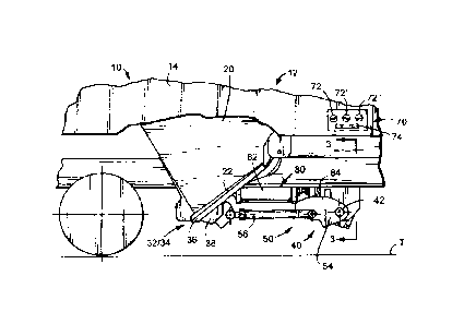
electrically operated touch pad assembly 70 is conveniently and preferably
located on each side
of car 10 to allow for selectively powered movement of the element 36 of each
discharge
mechanism 32, 34 between closed and open positions. In the form shown in FIG.
1, touch pad
assembly 70 includes three electrical contacts or buttons 72, 72' and 72" and
an elongated
electrical pad 74 for individually operating the discharge mechanism
associated with each chute
26 of the hopper 12. Of course, if hopper 12 is provided with a greater or
lesser number of
chutes 26 than three, touch pad assembly 70 would be reconfigured accordingly.
[0046] One form of an electrical circuit associated with the touch pad
assembly 70 is
schematically represented in FIG. 8. Selectively connecting any one of the
contacts 72, 72' and
72'' in combination with the pad 74 to an electrical supply source controls
operation of solenoids
76, 76' and 76" carried on the car 10. As will be appreciated, each solenoid
76, 76' and 76" is
operably associated with conventional valve structure including valves 77, 77'
and 77',
respectively, for directing power which, in the illustrated embodiment is air,
from a suitable
power source 79 to affect either powered opening or closing movements to the
discharge
mechanism associated with a particular chute 26 on the hopper 12.
[0047] In the illustrated embodiment, a drive mechanism 80 is operably
connected to the linkage
system 50 associated with each set of discharge mechanisms associated with
each chute 12. In a
preferred embodiment, and as shown in FIGS. 1 and 4, the drive mechanism 80
includes a
powered driver 82 for selectively operating the linkage system 50 to either
simultaneously move
-16-
CA 02710355 2010-07-16
the elements 36 of each discharge mechanism into their closed position or to
simultaneously
move the elements 36 of each discharge mechanism 32, 34 from their closed
position toward an
open position (illustrated in phantom lines in FIG. 1).
[0048] In a preferred form, the driver 82 for each control apparatus includes
a linearly
distendable motor, i.e., a pneumatically operated cylinder. In the illustrated
embodiment, and
through operation of one of the solenoids 76, 76' or 76" (FIG. 8), air is
selectively introduced
toward either: the fixed end, to positively distend and operably lengthen the
driver 82; or, the free
or operative end to cause the operative length of the driver 82 to positively
retract, in length.
[0049] In the form shown for exemplary purposes, a lever 84 radially extends
from and is
secured at one end to the operating shaft 42 and is operably connected to the
operative end of
driver 82. As such, linear extension/retraction of the driver 82 results in
rotation of the lever 84
about a predetermined path of travel and rotation of the operating shaft 42
about axis 44.
[0050] An indicator system 90 is mounted on the railcar 10 for providing a
visual indication
whether the lock for maintaining the movable element of each discharge
mechanism on the
hopper car is in either a locked or unlocked condition. Notably, the system 90
is capable of
providing a visual indication observable by a person located either proximate
to or remote from
the hopper car 10 of a condition of the lock arranged in operable combination
with the discharge
mechanism. As explained hereinafter, system 90 is preferably operable in: an
"operational"
mode; a "rest" mode; and an "indicator" mode.
[0051] In the form shown in FIG. 9, the indicator system 90 includes electric
circuitry, generally
identified by reference numeral 92, connected to a power source 94 which, in
the preferred
embodiment, is a conventional rechargeable battery carried on car 10. In the
illustrated
-17-
CA 02710355 2010-07-16
=
embodiment, the power source 94 is connected to a solar energy panel 96
mounted on railcar 10.
The electric circuitry 92 includes sensor technology 100 for monitoring the
condition of the lock
for each discharge mechanism and for controlling operation of an illuminable
indicator 110 as a
result of signals from the sensor technology 100 indicative of the condition
of the lock for the
railcar discharge mechanism. Although the indicator system 90 shown in FIG. 9
has been
simplified, it is to be understood the indicator system 90 of the present
disclosure monitors the
condition of the lock - in whatever form or design selected for use - of each
discharge mechanism
- in whatever form or design selected for use - associated with each discharge
opening - in
whatever form or design selected for use - on the hopper 12.
[0052] The sensor technology 100 includes a sensor 102 which, as shown in FIG.
6, is mounted
on railcar 10 by a suitable bracket or the like 101 for monitoring movement of
a member of each
discharge mechanism lock relative to a predetermined position. In a preferred
form, and although
only one sensor is illustrated in FIG. 9, the number of sensors used as part
of or with the sensor
technology 100 is equal to the number of discharge mechanism locks on the
railcar 10. For
example, if the railcar 10 was equipped with three discharge openings, the
sensor technology
would include three sensors 102; with one senor monitoring movement of a
member of each
discharge mechanism lock relative to a predetermined position.
[0053] In the embodiment shown in FIGS. 5, 6 and 7, each sensor 102 is mounted
on the railcar
for monitoring movement of a respective discharge mechanism lock member 54
relative to a
predetermined position and for providing signals to the illuminable indicator
110 as a result of
movement of the lock member relative to the predetermined position. In effect,
each sensor 102
detects whether the respective discharge mechanism lock member 54 is in a
position indicative of
-18-
CA 02710355 2010-07-16
=
the lock being locked or unlocked. That is, each sensor 102 produces a first
signal only when the
lock for the associated railcar discharge mechanism is in one, i.e. locked,
condition, and each
sensor 102 produces a second signal only when the lock for the associated
railcar discharge
mechanism is in another, i.e. unlocked, condition. Of course, and particularly
with different
discharge mechanisms, the sensor 102 can be arranged to monitor movement of
other members
which move with the lock for the particular discharge mechanism. As such, any
mental guessing
by the operator of whether the lock is locked or unlocked is eliminated.
[0054] Preferably, sensor 102 is an inductive proximity switch of the type
manufactured by
Contrinex AG and sold under Model Number: DW-AS-713-M12. Of course, other
types and/or
models of sensors can be used in combination with system 90 without detracting
or departing
from the spirt and novel scope of this invention disclosure.
[0055] In one form, the illuminable indicator or display 110 for system 90
includes at least two
illuminable displays 112 and 112' (FIG. 9) for visually indicating the
conditions of each
discharge mechanism lock on the rail car 10. In one form, the displays 112 and
112' are mounted
on opposed sides of the railcar 10. As such, the condition of each discharge
mechanism lock can
be viewed from either side of the car 10 on display 112, 112'.
[0056] Alternatively, and with a relatively simple design change, the display
110 can include
only one pair of illuminated displays 112, 112'; with one display being
arranged on each side of
the car 10. In this alternative embodiment, the display 110 is operated as a
collective function of
signals delivered to the circuitry 92 by each sensor 102 operably associated
with the lock
operably associated with each discharge mechanism on the railcar 10. That is,
if the lock
operably associated with each discharge mechanism on the railcar 10 is in a
locked condition, the
-19-
CA 02710355 2010-07-16
display 110 would provide an illuminated visual indication that each discharge
mechanism lock
in a locked condition. On the other hand, and in this alternative embodiment,
if any one or more
of the locks on the plurality of discharge mechanisms was in an unlocked
condition, and even
though the remainder of the discharge mechanism locks were properly in the
locked condition,
the display 110 on the railcar would indicate at least one of the discharge
mechanism locks was
in an unlocked condition. Accordingly, and at a quick glace of the car 10
either proximate to or
remote therefrom, an operator would be quickly alerted that at least one of
the discharge
mechanism locks required attention before allowing the car 10 to proceed
between locations.
[0057] Preferably, the illuminable displays 112. 112' are identical relative
to each other and, thus,
only display 112 will be described in detail. Each display is electrically
powered and controlled
by signals from the sensor technology 100 to indicate whether the lock for the
railcar discharge
mechanism is in a locked or unlocked condition. In one form, the indicator or
display 112
includes at least one light 114 operable in either of two states for
indicating whether the lock for
the railcar discharge mechanism is in a locked or unlocked condition.
Preferably, however, and
as shown in FIG. 9, each indicator or display 112 includes two lights 114 and
116. In this
embodiment, light 114 emits illumination when the lock for the railcar
discharge mechanism is in
one condition, i.e. a locked condition, and with light 116 emitting
illumination when the lock for
the railcar discharge mechanism is in a different, i.e., unlocked condition.
In one form, a first
color, i.e., red, is emitted by each illuminable indicator or display 112,
112' when the first light
114 is illuminated, and wherein a second color, i.e., green, is emitted by
each illuminable
indicator or display 112, 112' when the second light 116 is illuminated.
[0058] An automated system, generally identified in FIG. 9 by reference
numeral 130, is
-20-
CA 02710355 2010-07-16
frequently arranged at a site wherein material is to be discharged from car
10. As shown in FIG.
8, and to affect powered operation of the discharge mechanism on car 10,
conventional electrical
contacts or pick-up shoes 132 and 132' can be mounted on and extend laterally
past opposed
sides 14 and 16 of railcar 10. The disposition of the shoes 132, 132' allows
for automated
operation of the discharge mechanisms regardless of the direction of car
travel. Each shoe 132,
132' is electrically connected to the circuitry 92 of the indicator system 90.
[0059] As is known in the art, and at the material dump site, an electrified
rail or other suitable
electric conducting device 142 is arranged adjacent to the tracks T on which
car 10 rides. When
hopper car 10 moves toward the discharge site to exhaust material from car 10
and either shoe
132 or 132' contacts the electrified rail 142 , the solenoids 76, 76' and 76"
carried on the car 10
actuate the valves 77, 77' and 77" (FIG. 8) whereby directing power to each
drive mechanism 80
on the car 10 to affect powered opening of each discharge mechanism on the car
10. As
mentioned above, when the drive mechanism 80 of the discharge mechanism on
hopper car 10 is
activated, the lock maintaining the movable element of the discharge mechanism
in a closed
position is concurrently moved to permit the movable discharge element of each
discharge
mechanism to move toward an open position.
[0060] Preferably, the contact of either shoe 132, 132' with the electrical
conducting device 142
also directs power to the indicator system 90 during an "operational mode" of
the indicator
system 90. As such, the movement of each lock member, i.e. lever 54, from a
predetermined
position is detected by the associated sensor technology 100 which directs an
electrical signal to
the illuminable indicator or display 110. Accordingly, the illuminable display
110 is controlled
by the signal from the sensor technology 100 to provide a visual indication on
each display 112,
-21-
CA 02710355 2010-07-16
112' showing the lock for each discharge mechanism has been moved to an
unlocked condition.
[0061] As mentioned above, the illuminable display 110 is capable of visually
showing the
condition of the locks individually or collectively through any of several
techniques. Notably,
however, each technique used by display 110 involves the use of illumination
or the lack thereof
for indicating the condition of the discharge mechanism lock. The use of
illumination in
connection with the display 110 advantageously allows a person located either
proximate to or
remote from the railcar to quickly and easily access the condition of the
railcar discharge
mechanism locks simply by viewing the display 110. Of course, using
illumination in connection
with the display 110 to indicate the condition of the locks will furthermore
quickly and readily
permit evaluation of the condition of the locks regardless of the lighting
conditions in which the
hopper car happens to be so disposed.
[0062] When the hopper car discharging material has traveled sufficiently
along the tracks and
relative to the dump site or an operator disconnects the electrified rail 142
from the electrical
power source, electrical power to the solenoids 76, 76' and 76" (FIG. 8) is
removed. The loss or
disconnection of electrical power to the shoe or electrical contact 123, 132',
causes the solenoids
76, 76 and 76' to return the valves 77, 77' and 77" (FIG. 8) to their original
state whereby
returning the discharge mechanisms on the car 10, preferably under power, to a
closed position.
[0063] When each discharge mechanism on hopper car 10 is returned to the
closed position, the
railcar discharge mechanism lock operably associated with the movable element
of the respective
discharge mechanism is likewise moved toward a locked condition to inhibit the
movable
discharge element of each mechanism from inadvertently moving toward an open
position. In
the illustrated embodiment, returning movement of the lock member, i.e. lever
54, to its
-22-
CA 02710355 2010-07-16
=
predetermined position is detected by the sensor technology 100 which, only
after each lock
member 54 returns to that predetermined position wherein the railcar discharge
mechanism is
fully locked, directs an electrical signal to the display 110. Accordingly,
the display 110 is
controlled by the sensor technology 100 to provide a visual indication on the
display 100
showing the lock for the discharge mechanism has been returned to a locked
condition.
[0064] Notably, and following the loss of power to the indicator system or
apparatus 90 from the
electrified rail or other suitable electric conducting devices 142, and as the
railcar 10 travels away
from the discharge site, the illuminable indicator system 90 preferably
continues to operate in the
"operational mode". The independent power source 94 permits the illuminable
display or
indicator 110 to continue to operate and provide an illuminated indication of
the condition of
preferably each lock for each railcar discharge mechanism. Again, the use of
illumination in
connection with display 110 allows a person, located either proximate to or
remote from the
railcar, to quickly and easily access the condition of the lock simply by
viewing the display 110.
[0065] In a preferred embodiment, and as shown in FIG. 9, the electrical
circuitry 92 of the
indicator system 90 is provided with a timer 150 for controlling the duration
of the "operational
mode". That is, the timer 150 controls the amount or length of time the
display or indicator 110
is illuminated after each railcar discharge mechanism is operated by the drive
mechanism 80 to
move the discharge element of the mechanism between positions. Preferably, and
to allow the
power source 94 to maintain an adequate charge, the indicator 110 will remain
operable during
the "operational mode" only for a predetermined time period measured from the
time each
discharge mechanism on the railcar 10 is operated by the drive mechanism 80 to
move the
discharge element of the mechanism between its operable positions.
-23-
CA 02710355 2016-11-29
[0066] The ability of the display 110 to provide an illuminated indication of
the condition
of the lock for each discharge mechanism readily yields further advantages.
That is, and as
shown in FIG. 9, arranging a conventional reader or other suitable means 160
adjacent to the
discharge site, the condition of the lock for each discharge mechanism on the
hopper 12 can
be viewed, recorded and maintained for further use as the hopper car 10 leaves
the discharge
site.
[0067] Alternatively, a transmitter 162 is preferably arranged in operable
combination with
the electric circuitry 92 for transmitting a signal indicative of the
condition of the lock on
each discharge mechanism. In the illustrated embodiment, a signal transmitter
162 is
arranged in operable combination with the sensor technology 100 or other
suitable
component of the electric circuitry 92 for producing a signal indicative of
the condition of the
lock associated with each discharge mechanism in the car 10. As such, the
condition of the
lock associated with each railcar discharge mechanism can be determined from a
location
remote from the car 10 based on signals transmitted by transmitter 162. Upon
expiration of
the predetermined time set by timer 150, the illuminated system 90 preferably
shifts or
changes into a "rest" mode wherein the illuminable indicator 110 is not
illuminated.
[0068] In a preferred form, the electrical circuitry 92 can further include a
manually
operated switch 172 in operable combination therewith. The purpose of switch
172 is to
condition the indicator system 90 into an "indicator mode" of operation. That
is, switch 172
connects the power source 94 to the electric circuitry 92 whereby enabling an
operator,
through manual operation of switch 172, to quickly and easily access the
condition of the
discharge mechanism locks on the car 10 whenever required or desired.
[0069] During operation of the indicator system 90, a problem can occur with
any one or
more of
-24-
CA 02710355 2010-07-16
the following: the sensor technology 100; the illuminable indicator or display
unit 110; or the
lock on each discharge mechanism of car 10. Accordingly, the electric
circuitry 92 furthermore
preferably includes logic circuitry 168 for performing diagnostics relating to
the components of
the indicator system 90. Moreover, and in a preferred form, the logic
circuitry 168 is capable of
controlling the illuminable indicator or display unit 110 in such a manner or
mode as to provide a
visual indication on the display 110 of a problem with any one or more of the
following: the
sensor technology 100; the illuminable indicator or display unit 110; or the
lock on each
discharge mechanism of car 10.
[0070] The indicator system 90 can also embody alternative electric circuitry,
generally
identified in FIG. 10, by reference numeral 192 for use in operable
combination with the
illuminable indicator 110. In the embodiment illustrated in FIG. 10, the
illuminable indicator
110 is only operational in an "indicator" mode. That is, with the circuitry
192 illustrated in FIG.
10, the illuminable indicator 110 is only operational to visually indicate as
a result of
illumination, or lack thereof, whether the discharge mechanism lock is
currently in a locked or
unlocked condition for as long as electrical power is provided to the system
90.
100711 In the embodiment illustrated in FIG. 10, an electrically operated
touch pad assembly 173
is conveniently and preferably located on each side of car 10 to allow for
selectively powered
movement of the movable element of each discharge mechanism concurrently
relative to each
other between closed and open positions. In the form shown in FIG. 10, each
touch pad
assembly 173 includes two electrical pads 175 and 175'. Each electric pad 175,
175 is
electrically connected to the electric circuitry 192 of the indicator system
90. As discussed
above, the indicator system 90 furthermore includes the sensor technology 100
for detecting and
-25-
CA 02710355 2010-07-16
monitoring whether the lock operably associated with each discharge mechanism
is in a locked
condition or an unlocked condition.
[0072] In the embodiment illustrated in FIG. 10, when electric power is
provided to either
contact 175, 175', power is likewise provided to the electric circuit 192 and
to the sensor
technology 100. If so desired, such electrical power can be provided to the
contacts 175, 175'
through any suitable and conventional and preferably portable hand held
apparatus. The sensor
technology 100 likewise receives power delivered to the contacts 175, 175' and
operates the
illuminable indicator 110 as a function of the predetermined position of the
respective lock
members, i.e., levers 54 relative thereto, and provides an illuminated
indication of the condition
of the discharge mechanism lock as long as electric power is provided to
either electrical contact
175, 175'.
[0073] From the foregoing, it will be observed that numerous modifications and
variations can
be made and effected without departing or detracting from the true spirit and
novel concept of
this invention disclosure. Moreover, it will be appreciated, the present
disclosure is intended to
set forth exemplifications which are not intended to limit the disclosure to
the specific
embodiments illustrated. Rather, this disclosure is intended to cover by the
appended claims all
such modifications and variations as fall within the spirit and scope of the
claims.
-26-