Note: Descriptions are shown in the official language in which they were submitted.
CA 02710902 2010-07-23
INTEGRATED CONDITION BASED MAINTENANCE SYSTEM FOR
WIND TURBINES
Related Application
[0001] This application claims priority to United States Provisional
Application serial number 61/228,443 (entitled INTEGRATED CONDITION
BASED MAINTENANCE SYSTEM FOR WIND TURBINES, filed July 24, 2009)
which is incorporated herein by reference.
Background
[0002] Wind turbines often operate in severe, remote environments and
require frequent scheduled maintenance. The cost of unscheduled maintenance
due
to undetected failures is high both in maintenance support and lost production
time.
Brief Description of the Drawings
[0003] FIG. I is a block diagram of a health monitoring system for a wind
turbine generator according to an example embodiment.
[0004] FIG. 2 is a block schematic representation of systems and the
information collected in each according to an example embodiment.
[0005] FIG. 3 is a flow diagram of a method of monitoring the condition of
a wind turbine generator according to an example embodiment.
[0006] FIG. 4 is a block diagram of a computing device for implementing
one or more algorithms according to an example embodiment.
Detailed Description
[0007] In the following description, reference is made to the accompanying
drawings that form a part hereof, and in which is shown by way of illustration
specific embodiments which may be practiced. These embodiments are described
in
sufficient detail to enable those skilled in the art to practice the
invention, and it is to
be understood that other embodiments may be utilized and that structural,
logical
I
CA 02710902 2010-07-23
and electrical changes may be made without departing from the scope of the
present
invention. The following description of example embodiments is, therefore, not
to
be taken in a limited sense, and the scope of the present invention is defined
by the
appended claims.
[0008] The functions or algorithms described herein may be implemented in
software or a combination of software and human implemented procedures in one
embodiment. The software may consist of computer executable instructions
stored
on computer readable media such as memory or other type of storage devices.
Further, such functions correspond to modules, which are software, hardware,
firmware or any combination thereof. Multiple functions may be performed in
one
or more modules as desired, and the embodiments described are merely examples.
The software may be executed on a digital signal processor, ASIC,
microprocessor,
or other type of processor operating on a computer system, such as a personal
computer, server or other computer system.
[0009] Condition based maintenance (CBM) enables high reliability and low
maintenance costs by eliminating unnecessary scheduled maintenance through
continuous monitoring. An integrated condition based monitoring system
accounts
for health monitoring of the performance degradation of a core process,
mechanical
system faults, such as bearings, shafts and gears, electrical system faults
such as
power electronics, controller, and generator faults, and material or
structural faults,
such as fatigue cracks and corrosion in a wind turbine. In addition, condition
based
monitoring may include a system-wide reasoner and decision support software
that
isolates the right causes of failure and prioritizes maintenance actions.
Multiple
systems are targeted for monitoring through the use of one integrated hardware
box
for data collection and an integrated analysis and software system for
dissemination
of results.
[0010] Two major challenges are the improvement of wind turbine
performance and reduction in operating and maintenance costs. After the
capital
costs of commissioning wind turbine generators, the biggest cost for owners is
maintenance. A reduction in maintenance and operating costs can reduce a
payback
period considerably and can provide the impetus for investment and widespread
2
CA 02710902 2010-07-23
acceptance of this clean energy source, helping to achieve a goal of 20% of
electrical demand being supplied by wind energy.
[0011] A comprehensive integrated CBM system for equipment or processes
accounts for health monitoring of (1) the performance degradation of the core
process, (2) mechanical system faults (such as bearings, shafts and gears) (3)
electrical system faults (such as power electronics, controller, generator
faults), (4)
material or structural faults (such as fatigue cracks and corrosion) and (5)
hydraulic
system faults. In addition, a system-wide reasoner and decision support system
isolates the right causes of failure and prioritizes maintenance actions.
[0012] In one embodiment, the integrated condition based maintenance
system utilizes one electronics box that collects data from all sensors and
sensor
systems. Such sensors and sensor systems may include accelerometers and
tachometers for vibration monitoring of bearings and gearboxes, sensor data at
the
wind turbine controller, or supervisory control and data acquisition (SCADA),
generator electrical signals, structural health sensors such as fiber optic
strain sensor
system, and any other subsystem monitoring device. The system uses a data
transmission and communication systems, such as HUMS (health and usage
monitoring system), including a MWS (maintenance work station) and iMDS
(intelligent machinery diagnostic system) web server. Analysis software has
the
ability to reason amongst the health indicators from different subsystems to
resolve
conflicts amongst indicators, and provide a prioritized list of maintenance
actions.
[0013] In one embodiment, the combination of SCADA monitoring and
condition monitoring, including vibration and structural health monitoring in
a
single system provides an integrated view of the system health. Examples of
sensed
parameters for different parts of the wind turbine generator include
vibration,
temperature and speed sensors for mechanical systems. Pressure and
temperatures
may be sensed for hydraulic systems. Current, voltage, power, and vibration
may
be sensed for electrical systems. Vibration, strain, direct defect sensing
through
ultrasonic sensing, acoustic emission, etc., may be used for structural
systems.
Electronic systems may be monitored by collecting control/actuation signals,
performing signal injection etc. Performance monitoring in one embodiment
3
CA 02710902 2010-07-23
includes all controller data, including rotor and generator speeds, power,
yaw,
pitch, current, voltage, temperatures.
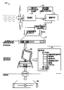
[00141 A condition based maintenance system 100 for a wind turbine
generator is shown in block diagram form in FIG. 1. System 100 in one
embodiment includes a blade structure 110, gearbox 115 coupled to the blade
110, a
drive train or shaft 112 coupling the gearbox 115 to a generator 120, an array
of
sensors 125 positioned to monitor the system 100, and a controller 130 to
control
the wind generator and collect data from the sensors 125. A plurality of
processing
elements such as maintenance station 135, ground station 140, and central
controller
150 may be located in a nacelle of the wind generator or on the ground, and
interconnected either wirelessly or by wired connections.
[00151 Instrumentation and data collection is the basic infrastructure
utilized
in CBM system 100. Sensors 125 include sensors for both SCADA monitoring and
vibration monitoring. Many different types of sensors may be used for
different
systems in CBM system 100. For example, as shown a block schematic
representation in FIG. 2, sensors and electrical signals are collected to
determine the
overall health of an integrated set of systems. Sensors used for a mechanical
system
210 that includes gearbox 115, bearings, and the drive, train include
vibration,
temperature, and speed such as tachometer sensors.
[00161 An electrical system 220 includes the generator 120, and pitch and
yaw motors. Current, voltage, power, and vibration information may be utilized
to
measure the health of the electrical system.
[00171 A hydraulic system 230 for pitch control may utilize pressure and
temperature sensors. A structural system 240 includes rotor blades and a tower
used
to support the wind turbine generator above the ground. The structural system
240
may include vibration and strain sensors. Direct defect sensing may be
performed
through ultrasonic sensing, acoustic emissions, and other types of sensing.
[00181 An electronic power system 250 may include control/actuation
signals and signal injection, etc. A performance monitoring system 260
monitors
the overall wind turbine performance, and includes all controller data,
including
rotor and generator speeds, power, yaw, pitch, current, voltage, and
temperatures.
4
CA 02710902 2010-07-23
Other parameter may be measured in further embodiments. Together, all the
sensed
parameters and signals comprise an integrated CBM as indicated at 270.
[00191 Mechanical failure modes such as bearing failures may be sensed and
anticipated prior to failure occurring such that maintenance may be scheduled
to
minimize wind turbine generator down time.
[00201 The system 100 may be used for reducing, even eliminating, required
scheduled maintenance, identifying faults that would not have been detected
under
existing maintenance procedures, reducing unscheduled component
removal/replacement. The vibration monitoring system includes real-time data
collection and processing component 130 to be installed in the wind turbine
nacelle,
along with maintenance station 135 for download, summary, and specification of
maintenance actions for the user. Real-time data collection and processing
component 130 receives SCADA data, such as all controller data, including
rotor
and generator speeds, power, yaw, pitch, current, voltage, and temperatures.
The
maintenance station 135 may be located in the nacelle, and collects and
records
sensed vibration data and SCADA data. Maintenance station 135 may also perform
some data pre-processing and feature extraction computations.
[00211 The system 100 includes monitoring system sensors 125, and rack-
mounted equipment such as station 135 for at-site data collection and
processing.
Still further environmental sensors may be used to provide further data to
maintenance station 135.
[00221 A computer that runs ground station 140 software may be used by the
maintenance station 135 for download, summary display, and recommendation of
action items for one or more wind generators as indicated in block 145 showing
a
tree representation of a wind generator farm that includes multiple towers
with
components listed for tower 1. Ground station 140 may also perform detection
and
diagnostic algorithms, as well as prognostic and remaining life algorithms.
[00231 All data collected by GBS systems can be seamlessly downloaded to
an intelligent Machinery Diagnostic System (iMDS) Server or central controller
150
for archive and analysis. Central controller 150 may perform reasoning to make
CA 02710902 2010-07-23
maintenance scheduling decisions, including prioritization. The entire system
may
be configured using a software tool called the iMDS Database Setup Tool.
[0024] In further embodiments, multiple ground stations 140 may be
coupled to the central controller 150 via a network connection, such as the
Internet.
[0025] Algorithms for processing the sensor data may be performed at one
or more of the processing component 130, maintenance station 135, ground
station
140, and central controller 150 in various embodiments. In one embodiment,
central controller 150 may be used to coordinate maintenance efforts for
towers
located on one or more farms based on predictive maintenance actions generated
from the collected data for each wind generator on a tower.
[0026] Condition based maintenance (CBM) and performance monitoring
have a much broader potential for operator/owner benefit than just basic
monitoring
for mechanical failures. The system 100 utilizes gathered information on the
top
failure modes from wind farm operators, data from wind turbine SCADA feeds,
and
diagnostic and prognostic analytics to complement established HUMS mechanical
condition indicators.
[0027] Top failure modes are identified that can benefit from CBM by
gathering information from actual operating wind turbine generators and
comparing
the data to actual failures. SCADA data for multiple wind turbines or for an
entire
wind farm may be gathered to help identify the failure modes to help develop
fault
detection algorithms.
[0028] Anomaly detection for individual wind turbines may be developed
with a data set collected. Analysis may be done but is not limited to using
principal
component analysis (PCA), and non-linear methods. For example, SOFM (Self
Organizing Feature Maps) is a non-linear method by which unsupervised learning
can be used in a set of data with unknown features, for categorizing them into
groups with similar features. A set of algorithms that look for anomalies in a
sensor
within a sensor group may be used in detecting anomalies with the SCADA data.
[0029] In one embodiment, performance monitoring using anomaly
detection may be used for a population of wind turbines, such as those on a
wind
farm. The relationship at the system level, between different wind turbines on
the
6
CA 02710902 2010-07-23
farm may be exploited. Each wind turbine in a particular wind farm or
geographic
location has a relationship to the other wind turbines operating in its
vicinity, in
terms of wind speed experienced, rotor speed, and generator output.
Correlation
and monitoring on a continuous basis may be done to determine if the
relationship is
broken because of an anomaly. Scatter plots and confidence interval
thresholds, for
raw data as well as PCA outputs such as Q-statistics may be used to perform
the
correlation.
[00301 In one embodiment, different CBM configurations may be used for
different wind turbine models The setup tool provided with Honeywell's ZingTM
Ware HUMS software works well to define configurations that are set up once
and
duplicated over multiple machines. The setup tool capability is extensive,
allowing
aircraft as diverse as the Chinook Helicopter (CH-47D) and Blackhawk (UH-60)
to
be configured without source code changes. This level of flexibility enables
rapid
configuration and tuning of HUMS algorithms and is a significant factor in the
success of Honeywell's HUMS deployment. In one embodiment, the wind turbine
CBM system employs a similar level of flexibility and system integration. A
reference model may be defined for wind applications using a structure similar
to
Honeywell's HUMS data model. The reference model includes equipment
characteristics and key tuning parameters for all subsystem health monitoring
algorithms.
100311 In some embodiments, various analytics may be used for advanced
CBM system 100. Additional diagnostic and prognostic analytics are described
below. Different mathematical and statistical techniques may also be used.
These
techniques include but are not limited to, PCA/PLS, clustering, trend
analysis,
neural networks, data fusion, knowledge fusion and others.
[00321 Statistical techniques may be used to monitor rotor performance for
given wind speeds by comparing actual versus expected. Generator power
produced
can also be monitored in the same way. In one embodiment, icing detection may
also be performed utilizing specific seasonal performance features and weather
conditions.
7
CA 02710902 2010-07-23
[0033] Anomaly detection for a wind turbine population may be performed.
The wind turbines in a wind farm do not experience identical conditions.
During
normal operation, the wind turbines may have a certain correlation with each
other.
An evolving fault in one wind turbine could show up as an anomaly in the
population data, which can be integrated as additional conditions to those
available
with the HUMS based system.
[0034] Generator electrical characteristics in the SCADA data may be used
to detect generator electrical and mechanical problems.
[0035] Generator fault detection may be performed using analytics based on
the generator electrical characteristics.
[0036] Health monitoring may be performed to improve turbine reliability
and reduce operation and maintenance costs through continuous monitoring of
wind
turbines. Condition Based Maintenance (CBM) technology is applied to wind
turbines.
[0037] Early detection of component failures that cause the highest failures
in wind turbines are addressed by the system 100. Operational failures
associated
with the gearbox 1] 5 and generator components 120 are significant, accounting
for
the largest downtime and expense for repair. The system 100 provides accurate
prediction of bearing and gearbox mechanical failures through vibration
monitoring.
Performance, electrical and blade 110 structural monitoring cover high impact
failures in the rest of the subsystems. Comprehensive health analysis provided
by
system 100 provides full coverage of the highest cost and most frequent
failures,
resulting in reduction in cost of unscheduled maintenance, longer scheduled
maintenance intervals, shorter downtimes that reduce loss of revenue, and
optimum
maintenance scheduling.
[0038] In one embodiment, the system 100 is configurable for application to
new sensors, new algorithms, and new equipment types and components by
changing database setup tables. The system can also input SCADA bus data,
which
will enable use of the architecture in various wind turbine CBM integrations.
[0039] The vibration measurement and diagnostic processing may be used to
develop component-specific diagnostics that provide robust indicators of
8
CA 02710902 2010-07-23
mechanical faults. To develop robust indicators, factors such as sensor
location and
type, measurement, diagnostic processing, and limits setting are taken into
account.
The data collection hardware also embeds sophisticated processing capability
including Asynchronous Time Domain (ATD), Synchronous Time Domain (STD),
Asynchronous Frequency Domain (AFD), and Synchronous Order Domain (SOD).
The accelerometer and tachometer data collected is pre-processed with these
methods. Several vibration monitoring algorithms operate on the data
structures thus
produced and output condition indicators. These include Spectral Peak 1 and 4,
Envelope analysis, figure of merit 0 and 4, and many others.
[00401 Automated anomaly detection algorithms use wind turbine
supervisory control and data acquisition (SCADA) data. Predictive trend
monitoring (PTM) and the ZingTM family of products for aircraft engines and
auxiliary power units (APU) as well as event detection methods from the
process
industry may also be used. Performance monitoring includes analysis of data
using
proven mathematical and statistical approaches.
100411 Performance is described in the context of the underlying process
physics of the wind turbine, and may use model-based and data-based
approaches.
As the turbine components deteriorate, the efficiency with which wind energy
is
converted to electrical energy decreases. Performance degradation can indicate
a
number of problems, such as blade aerodynamic degradation due to leading and
trailing edge losses, dirt or ice buildup on blades, loss due to drivetrain
misalignment, friction caused by bearing or gear faults, generator winding
faults, or
even pitch or yaw control system degradation. Performance parameter
calculation,
anomaly detection, fault diagnosis, predictive trending and future projection
may be
used in various embodiments.
[00421 Model-based diagnostics may be used to detect faults and
degradations. Using a wind turbine model, and operating conditions, model-
prediction residuals are computed. Fault parameter severities are then
estimated
based on the residuals. Techniques such as generalized least squares (GLS) may
be
used for estimation of fault parameters.
9
CA 02710902 2010-07-23
[00431 In one embodiment (PCA) is used to process sensed information
about the system 100. Multivariate statistics may be applied to complex
processes
to provide better indication of problems than univariate statistics. One
approach to
detecting changes in process performance is to use PCA and partial least
squares
(PLS) regression.
[00441 Using PCA, the analysis of a large number of process variables from
an area or sub-process is reduced to a subset of linear combinations. These
linear
combinations of process variables are also known as latent variables. The
original
inputs can be thought of as projecting to a subspace by means of a particular
transformation. Unlike the raw inputs, the latent variables are guaranteed to
be
independent.
100451 A plane of normal operation establishes a benchmark from which to
judge future process states. Confidence limits are established around this
plane or
model to determine the boundaries of the subspace. Fault detection or process
monitoring is done by periodically taking new values of the input variables
that
represent a new process condition or state. Early detection of changes in the
process
can be detected as the statistics either leave the model hyperplane or exceed
statistical limit boundaries within the hyperplane.
100461 Self-organizing feature maps may also be used. Clustering
algorithms are methods to divide a set of n observations into g groups so that
members of the same group or cluster are more alike than members of different
groups. A self-organizing feature map (SOFM) is a type of unsupervised
clustering
algorithm, forming neurons located on a regular grid, usually of I- or 2-
dimensions.
SOFM can detect regularities and correlations in their input and adapt their
future
responses to that input by learning to classify input vectors. Based on the
competitive learning process, the neurons become selectively tuned to input
patterns
so that neurons physically near each other in the neuron layer respond to
similar
input vectors. Since the health condition (normality or failure) for each data
point is
not available in the field, SOFM is particularly suited to find patterns in
the data and
without target class labels. Honeywell possesses an original SOFM-based
technology and has utilized it in the area of fault diagnosis of gas turbine
engines.
CA 02710902 2010-07-23
[00471 Sensor validation, isolation, and recovery may also be performed.
Analytical redundancy among sensors is captured and the readings of a group of
correlated sensors are mapped into an estimation set of an identical group. In
the
nominal case, the association between the actual and the estimated values are
maintained, and the residuals remain small. However, when there is an
appreciable
sensor fault, the associated model estimate diverges from the actual sensor
reading.
This difference is driven by the fact that the associated model estimate is
not a time
series prediction but an expectation computed based on the remaining
associated
sensors that have not failed. Sensor recovery of appreciable sensor faults is
then
accomplished by taking advantage of this feature, and the divergence is
removed
incrementally by iterative associative model estimation feedback.
[00481 The published literature on wind turbine reliability shows that
unscheduled generator failure is a major contributor to the overall turbine
downtime.
System 100 targets generator fault detection using a hybrid approach that
utilizes
model and spectral analysis based methods of fault detection, along with an
advanced trending approach to generate the requisite generator prognostics
indicator. This approach for condition monitoring for the wind turbine
induction
generator system will cover both electrical and mechanical faults. The
approach
leverages experience with induction motor fault detection using both signature
and
model based methods to provide coverage for electrical and mechanical faults.
It
utilizes data collected from the generator terminal currents and voltages,
vibration
signals from the generator bearings accelerometers; and thermocouples
monitoring
the critical bearings, generator exciter and the generator windings. Within
this
construct the presence of multiple sensors is exploited; various sensing
modalities
along with known physics of failure or mechanistic models to calculate health
indicators for the actuator system. For example, in the case of generator
eccentricity, informational redundancy may be exploited by using one or both
the
bearing accelerometer signal and the generator voltage signature to detect the
underlying fault. The use of multiple sensor modalities improves the detection
accuracy and reduces false alarm rate of the diagnostics system.
11
CA 02710902 2010-07-23
[0049] Structural health monitoring of wind turbine blades may also be
provided in further embodiments. Fiber optic sensors may be used for
distributed
strain measurement of the blades. Structural models may be used to interpret
the
sensors to provide information on incipient structural defects, such as
location, size,
and probability of failure.
[0050] Structural health monitoring may also be used for tower structural
monitoring.
[0051] Usage based monitoring, diagnostics and prognostics of several
components may be performed. By keeping track of the operations (such as
speeds,
temperatures, starts and stops, hours or frequency of operation in particular
operating regimes) of components such as the gearbox, rotor, yaw and pitch
motors
and other components, usage based degradation can be monitored. Usage
statistics
also provide another piece of information and increase the confidence for
fault
diagnostics.
[0052] An effective approach for wind generator configuration and tuning is
used to ensure successful CBM deployment. A standard configuration approach,
using tools that facilitate broad deployment of health monitoring algorithms
to
multiple wind turbine configurations.
[0053] Equipment specifications and SCADA data configuration are
gathered across the multiple wind turbine models in operation. The information
may be used to define a reference model for wind applications. The reference
model may include equipment characteristics and key tuning parameters for both
HUMS and SCADA algorithms.
[0054] FIG. 3 is a flow diagram illustrating a computer implemented method
300 of monitoring wind generators for determining appropriate maintenance
actions
based on the sensed condition of the wind generators. At 310, wind turbine
condition sensor information is received from all sensors associated with the
system
100 in one embodiment. The data may be stored on a computer readable memory
device for immediate or future use. At 320, wind turbine controller
information
regarding electrical performance of the wind turbine is received and stored on
a
computer readable device. The information is then used at 330 by applying an
12
CA 02710902 2010-07-23
automated anomaly detection algorithm via the computer to identify maintenance
activities for the wind turbine integrating both vibration and SCADA data.
Maintenance activities are thus performed for the wind energy turbine in an
integrated manner as a function of both the wind turbine health sensor
information
and the wind turbine controller information.
100551 In further embodiments, the received information is processed via a
computer to convert to at least one of a time domain and a frequency domain
representation. The structural health sensor information may include one or
more of
strain, acoustic emission, and optical or piezoelectric sensor information.
Processing structural health sensor information may be done to produce an
image of
a monitored structure. Automating the structural health sensors may be done to
gather and transmit data at particular regimes of operation or at trigger
conditions.
[00561 In some embodiments, further sensor information such as at least one
of generator, gearbox bearing, and lube oil temperature, yaw position and
pitch
position information, rotor, gearbox, and generator speed, generator terminal,
currents, voltages, and power electrical signals may be received and used to
identify
maintenance activities. In still further embodiments, inner control loop data
may be
received and used. One example of such inner control loop data includes
demanded
and measured pitch angle. Further sets of data that includes variations from
requested control actions and actual measurements may also be used.
[00571 A block diagram of a computer system that executes programming
for performing the above algorithm is shown in FIG. 4. A general computing
device
in the form of a computer 410, may include a processing unit 402, memory 404,
removable storage 412, and non-removable storage 414. Memory 404 may include
volatile memory 406 and non-volatile memory 408. Computer 410 may include - or
have access to a computing environment that includes - a variety of computer-
readable media, such as volatile memory 406 and non-volatile memory 408,
removable storage 412 and non-removable storage 414. Computer storage includes
random access memory (RAM), read only memory (ROM), erasable programmable
read-only memory (EPROM) & electrically erasable programmable read-only
memory (EEPROM), flash memory or other memory technologies, compact disc
13
CA 02710902 2010-07-23
read-only memory (CD ROM), Digital Versatile Disks (DVD) or other optical disk
storage, magnetic cassettes, magnetic tape, magnetic disk storage or other
magnetic
storage devices, or any other medium capable of storing computer-readable
instructions. Computer 410 may include or have access to a computing
environment
that includes input 416, output 418, and a communication connection 420. The
computer may operate in a networked environment using a communication
connection to connect to one or more remote computers. The remote computer may
include a personal computer (PC), server, router, network PC, a peer device or
other
common network node, or the like. The communication connection may include a
Local Area Network (LAN), a Wide Area Network (WAN) or other networks.
[0058] Computer-readable instructions stored on a computer-readable
medium are executable by the processing unit 402 of the computer 410. A hard
drive, CD-ROM, and RAM are some examples of articles including a computer-
readable medium.
[0059] The Abstract is provided to comply with 37 C.F.R. 1.72(b) is
submitted with the understanding that it will not be used to interpret or
limit the
scope or meaning of the claims.
14