Note: Descriptions are shown in the official language in which they were submitted.
CA 02710932 2014-07-07
WO 2008/088225 PCT/N02007/000463
1
ROTATING DEVICE
Field of the Invention
The present invention relates to engine- and compression technique
Technical background
There are a lot of engine and compression techniques today built on pressure
and expansion of air by combustion, to run an engine, turbo and turbine.
Common for them is low thermal-efficiency, as compression before expansion is
=
energy demanding. There is also many movable parts, and other parts which
have to be assembled in current engines and compressors making them
io complex, expensive with a low wear ability and running-stop. To avoid
this,
frequently maintenance has to be done.
The gas turbine is one of the most energy economical, and safe running
engines today. But it is still a lot of resistance and energy loss in the
compression =
process and the engine is complex and expensive, besides it is not energy
economical when partially loaded, and therefore it is less suitable for
instance
as car engines.
Summary of the Invention
It is an object of the invention to provide a rotating device producing
pressure
by centrifugal pressurized fluid (liquid, gas or plasma) that afterwards is
expanded, and including aU-channel structure that includes an expansion
point at the periphery of the rotating device, and which includes a sink
channel
in said U-channel structure, and said sink channel is a pressure channel for
supply of pressurized fluid to said expansion point, and which include a rise
channel in said U-channel structure for transport of said expanded fluid from
said expansion point, to an outlet channel for said pressurized fluid to a
regulation valve for supplying said fluid of high pressure into an outlet
channel
for said pressurized fluid to an energy utilizations device, and drive means
to
rotate said U-channel structure, wherein said sink channel and rise channel is
connected together at the periphery and arranged radial on the shaft in said
3o device, and said U-channel structure is connected to the shaft in
balance with
two or more U-channel structures.
In an aspect, there is provided a rotating device for producing a pressure of
a fluid
by expansion, comprising: a U-channel structure extending radially from an
axis of
rotation of a shaft, wherein the rotating device is fitted within an anchored
housing
with bearings rotatably coupling the shaft to the housing, and wherein the U-
channel structure includes an expansion point arranged at a periphery of the
rotating device, a sink channel for supplying a pressurized fluid to said
expansion
point, a propellant channel that follows a contour of the sink channel and
provides
a propellant fluid to the expansion point, and a rise channel for supplying an
expanded fluid from said expansion point through an outlet channel to a
regulation
CA 02710932 2014-07-07
valve to supply said expanded fluid at a higher pressure than that of the
pressurized fluid to an energy utilization device, and wherein the sink
channel and
the rise channel are connected to one another at the expansion point where the
pressurized fluid is mixed with the propellant fluid.
Brief description of the drawings
The invention will now be described in detail in reference to the appended
drawings, in which: =
Fig. 1 is a longitudinal principle sketch through the first embodiment of the
invention,
la
CA 02710932 2010-06-28
WO 2008/088225 PCT/N02007/000463
2
Fig. 2 is a cross section of inlet side in sink channel through the embodiment
shown in fig. 1,
Fig. 3 is a cross section of outlet side in rise channel through the
embodiment
shown in fig. 1,
Fig. 4 is a longitudinal principle sketch through another embodiment of the
invention, with an example of connections to existing energy utilizations
devices,
Fig. 5 is a cross section of inlet side in sink channel through the embodiment
shown in fig. 4,
Fig. 6 is a cross section of outlet side in rise channel through the
embodiment
shown in fig. 4,
Detailed description
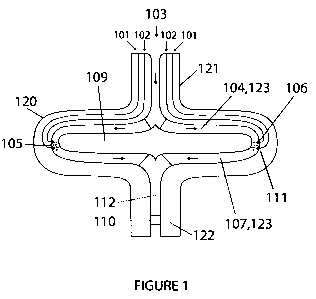
Fig. 1 shows the principal parts of the invention, namely a cylindrical drum
or
disc-like structure 120 with hollow shafts 121, 122. The shafts 121, 122 are
suspended in bearings and connected with drive means arranged to rotate the
disc 120 (not shown). The structure includes an inlet channel 103, in which
fluid
(example air) is supplied to compression and expansion. The inlet channel is
placed in the centre of the shaft 121, and branches out in a sink channel 104.
The fluid will be thrown outwards in the sink channel 104 due to centrifugal
forces. The sink channel 104 may be realized as a flat disk-like chamber,
possible with vanes, or as tubes or hollow spokes leading from the centre part
of
the disc to the periphery. In the embodiment shown in the figure, the vanes
123
will also act as support elements binding the structure together between the
channel partition disk 109, and outer part of the U-channel structure 120 and
shaft 121, 122. At the periphery, the pressurized fluid will get in contact
with
propellant nozzle 106 and spark plugs 111, respectively. The propellant nozzle
106 is supplying propellant in the propellant channel 102 from a drag chamber
(not shown) arranged on the shaft 121. The spark plug get high-voltage trough
electrical conductor 101 from a slip ring on the shaft 121 and trough the disc
structure 120 which is earthed (not shown).
The propellant nozzle 106 and the spark plug 111 are located at the periphery
in said U-channel, so that propellant from propellant nozzle 106 will be mixed
together with fluid. The mixture will ignite in expansion point 105 of the
spark
from the spark plug 111, after the propellant nozzle 106. The spark will stop
after
ignition. The expanding fluid will be pressed by the heavier fluid from sink
channel 104 further over to the rise channel 107, which may be a disc-like
chamber with radial walls 123, or a plurality of tubes or hollow spokes,
similar to
the input- 103 and sink channel 104. The rise channel 107 is connected to an
output channel 112 in the centre of the shaft 122, and further to a regulation
CA 02710932 2010-06-28
WO 2008/088225
PCT/N02007/000463
3
valve 110 which is adapted to regulate the fluid output at optimum pressure
and mass. The regulation valve 110 can be closed 310a, or open 310b.
The present invention is a rotating device where it is arranged two or more U-
like channels arranged radial 120, and in balance on the shaft 121, 122 with
inlet- 103 and outlet channel 112 in, or around the shafts 121, 122. During
high
rotation, the fluid (example air) will because of its mass be pressed by
centrifugal forces out towards the periphery of said U-channel. There fluid
from
inlet channel 103 is branched out in several sink channels 104, and it is
connected together with channels from periphery to outlet channel 112 with
rise channel 107. At high rotation, the fluid will be pressurized by its mass
towards periphery in sink channel 104. Then more fluid will flow into the sink
channels 104(when fluid are at compressible phase), and it will press the
fluid
further together. It will be a static-like high pressure of the fluid in the
channels
at periphery. In the invention, the pressure can be constant there in the
process, when the rotation is constant. And at the beginning is the heavy-
density in balance between sink channel 104 and rise channel 107, but when
influence on the fluid to lower heavy -density and then lower weight by
expansion (example by said combustion) from expansion point 105 in the fluid
channel at periphery and up rise channel 107, some of the fluid will expand
out
through outlet channel 112. Then it will be unbalance between the fluid in
sink
channel 104 and rise channel 107 causing the heavier (example colder) fluid
from sink channel 104 to be pressed at the periphery over to rise channel 107
and pressing the fluid there further to outlet channel 112. By the continuous
influence to expand (example combustion) the fluid, when it continuous passes
through the expansion point 105 at the periphery, it will form a continuous
move
towards outlet cannel 112. A pressure regulation valve (example adjustable
stator blades) 310 in the outlet channel regulates the output pressure
optimally,
so that the fluid in said U-channel only moves itself towards the output
channel.
And due to the higher expansion (lower heavy-density) in rise channel 107, the
higher pressure out of the invention device after the pressure regulation
valve
110 and by doubling the volume in rise channel 107 compared with sink
channel 104, the theoretical pressure out will be 50 % of the pressure at
periphery. By five times volume expansion, the pressure at the regulations
valve
in outlet will be 80 % of the presure for the fluid in the channel at the
periphery
and so on. The centers of gravity of the fluid in rise channels 107 will be
nearer
the shaft and the sum of the mass there will therefore experience a lower
centrifugal force than the fluid in sink channels 104 where the centers of
gravity
are nearer the periphery, because of larger pressure difference from input to
periphery (with compressible fluid), compared with rise channels 107 with less
pressure difference between periphery and outlet channel, and therefore will
said percent for pressure out be higher.
CA 02710932 2010-06-28
WO 2008/088225
PCT/N02007/000463
4
There are several methods to increase the density (reduce volume) of the mass
in sink channel 104 and to reduce the density (increase volume) of the mass in
rise channel 107, like for example:
For sink channel 104 to expanding point 105: n and/or before sink channel the
fluid can be a liquid, or at gas phase and cooled for higher density, and/or
the
fluid can be pumped/pressurized to inlet channel 103.
For rise channel 107 from expanding point 105: The fluid can for instance be
heated up within same phase, or over one or more phases, or be split for lower
density with catalyzing and/or electrochemistry, or similar, or any
combination
of said examples.
The advantage of the invention
The advantage of the invention is that pressure regulation 110 of the fluid
output creates a higher pressure out 112 than in 103, in the device. The
tangentially acceleration force on mass out towards periphery 104 will
practically be returned by the tangentially retardation force of the same mass
with transport from periphery, back to shaft in closed channels 107. When the
rotating device is arranged inside a evacuated housing (not shown), it will be
minimal rotary resistance, noise and heat loss. The device is compact, and
with
few movable parts, which give less frequently maintenance. In the device, the
produced output pressure can be used to produce energy.
The pressure from the inventive device can be conducted via energy utilization
devices such as: -turbo generator, -turbo loader, -turbine generator, -
pressure
motor, nozzle or injector for propulsion, or similar, or to accumulate the
pressurized fluid.
Said connected energy utilization devices can be adjusted optimum for a flow-
through- velocity, in such a way that regulation valve 110 for optimum
pressure
out is less necessary, and will therefore get a better energy economy.
Said energy utilization devices such as: -turbo generator, -turbo loader, -
turbine
generator, -pressure motor, can be installed external with connected channels
for fluid from the invention device. Or arranged on the same shaft as the
inventive device. Using for instance an axial turbine on the same shaft, the
inventive device will be like a centrifugal compressor-gas turbine/jet motor
which is less energy economical than the current inventive device. For
instance
is the compression more energy demanding, for the tangential acceleration
force (in sink channel 104 for the invention) will not be returned by the
tangentially retardation force (in rise channel 107 for the invention) of the
fluid,
as in the invention. In addition, a centrifugal compressor-gas turbine will
have
much more friction tangentially. This will nearly not occur in the present
invention, where the fluid practically have only friction axial and radial,
which is
CA 02710932 2010-06-28
WO 2008/088225
PCT/N02007/000463
relative low when the fluid move by itself in the closed channels 103, 104,
107,
112 in the rotating device, and the outside of the channels rotates in vacuum.
The fluid have relatively much higher periphery velocity then the flow through
velocity in the channels, and when the fluid only are in contact with the
5 channel walls, which on the outside are in vacuum, and with that the
current
rotating device can have a very high and constant rotation, without worth
mentioning rotation resistance, and at same density on the fluid in sink
channel
104 and rise channel 107, said fluid will not move in the channels, but when
expansion in rise channel 107, it will immediately move when during rotation
and form a pressure out as said earlier for the present invention.
Fig. 2 is a cross section through the U-channel structure 220 shown in fig. 1,
in
area of propellant nozzle 206 and spark plug 211. The fluid move into the
device through inlet channel 203 in centre and is forced to out towards to the
periphery, and tangentially accelerates along the shovel 223. But the radial
velocity can be constant when the fluid is pressurized in sink channel 204
where
it get in contact with the propellant nozzle 206 which added in proper
quantity
propellant. The spark plug 211 form a spark between the propellant nozzle 206
that start expansion of the fluid in expanding point 205, and then it will
move
first tangentially in the rotation direction, before it will be pressed
further axially
in to the periphery of rise channel 207. The figure also shows propellant
channel
202, and the insulated conductor 201 for high voltage to spark plug 211.
Fig. 3 is a cross section through the U-channel structure 320 shown in fig. 1,
in the
area of propellant nozzle 306 and spark plug 311. The fluid will get in
contact
with the propellant nozzle 306 that add in proper quantity propellant. Then,
the
spark plug 311 form a spark between the propellant nozzle 306 which start
expansion of the fluid in expansion point 305, whereupon it will moves first
tangentially in the rotation direction, before it will be pressed further
axially in
the periphery and then up along the shovels 323 and then tangential retards in
rise channel 307, and the radial velocity can be constant, and the fluid will
be
pressed further out in outlet channel 312 to regulation valve 310 which can be
regulated between closed 310a or open 310b. The figure also show propellant
channel 302, and insulated conductor 301 for high voltage to spark plug 311.
However, if the structure must be run at a lower temperature, for example
because of the material at high rotation does not tolerate high temperature to
expand the fluid, the energy supply can then be reduced and/or the heat can
then be reduced on the U-channel structure with heat exchange channels
which surround said fluid channels from inlet to outlet by supplying such as
water or steam or other suitable cooling medium in said heat exchange
channels in inlet, in proper quantity and pressure. Said heat exchange
channels
can be fitted with several longitudinal walls which are fastening to the
outer_
side of the fluid channel and to the inner side of the heat exchange channels,
both for better heat exchange and to strengthen the structure. The walls can
CA 02710932 2010-06-28
WO 2008/088225 PCT/N02007/000463
6
be perforated with several adapted small holes, or fewer larger holes, which
each have a sharp edge in the direction to the centre of the hole, to get less
resistance. The holes are in equal distance both for lightening the weight and
to
equalize the pressure of the cooling medium between the walls. In the same
way, it can be arranged corresponding longitudinal walls in the fluids sink
channel, so the cooling medium can cool down the fluid there, for further
compression of it, when it is compressible. The cooling medium, which can be
water, will thereby be endothermic first from the compressed fluid and
afterward from the energy supplied by the heat exchange from the expansion
of the fluid. The heat exchanging changes the cooling medium up its rise
channel to be over heated dry steam, which can be water steam, that have
essential lower density then the water in heat exchanges sink channels, and a
corresponding output pressure effect is achieved also in the heat exchange U-
channel structure, like for the fluid channels U-channel structure.
Fig. 4 shows a principle sketch of another embodiment of the invention, in
which four pipes form said U-channel structure 431, and which is fastened
radially and in balance towards the shaft which belongs to inlet- 405 and
outlet
channel 409. The fluid channels is; Inlet channel 405, sink channel 406, rise
channel 407, and outlet channel 409 and they are surrounded by heat
exchange channels; inlet channel 408, sink channel 423, rise channel 424 and
outlet channci 417.
The rotating pressure production unit is encapsulated and fitted in an
anchored
evacuated housing 413 with bearings and gaskets 414 around the inlet shaft,
and only a bearing with inner gasket at outlet shaft 416 with possibility for
a flow
through round bearing house 416. The evacuated housing is further fitted and
tightened around the end of the turbine house 415 which does not rotate, and
a vacuum is established inside the housing 413 by the vacuum pump 401. The
rotating unit starts the rotation with help from a pressure start motor 403
which
receives supplied fluid (for instance air) from an accumulator tank 411 via
its
regulations valve 421. By regulation of pressure fluid to the pressure start
motor
403, its drive wheel will be pushed in contact with the shaft in the
invention.
When the rotating speed has been established, the valve 421 will close and the
start motor's drive wheel will retract and out of contact with drive wheel= on
the
shaft, and a rotation maintenances motor 404 take over for constant rotation.
At the start of rotation, some water MI be pumped in to heat exchange cannel
408, such as the water level will be in proper distance from periphery in its
sink
channel 423 and rise channel 424. At the same time the valve 419 will open for
supply from accumulating tank 411 pressurized fluid to injector 422 which is
fitted to pull with more fluid from the ambient (air), or from a channel to
supply
other fluid (not shown) and in to inlet channel 405. Then the cooled fluid
will be
pressed to the sink channels 406 where the heavy density from the fluid will
pressurized further by the centrifugal force through the periphery where its
CA 02710932 2010-06-28
WO 2008/088225 PCT/N02007/000463
7
maximum pressurized, and where the fluid also gets in contact with the
propellant nozzle 427 where an adapted amount propellant mixing together
with the fluid, to be conducted further to the spark plug 428 ( supply channel
for propellant and the same for insulated conductor for high voltage to spark
plug, is not shown, but can be as in fig. 1) which ignite the propellant, so
it will
expand at constant pressure further over at periphery and up rise channel 407,
and out channel in shaft to fluid slip chamber 409 which not rotate, and is
connect with channel to turbine 410. From slip chamber 409 the expanded fluid
can go in two directions. One of them is to turbine 410, which inside can have
regulated stator blades similar to 310 in fig. 3, or similar which in the
start is
closed, in such a way that the fluid will be conducted in other direction for
recycle channel from slip chamber 409 to an heat exchanger and condenser
420, where moisture in the fluid separates out 426, so dry and cold fluid
further
will be pressed via regulation valve 419 which is accommodated for passage of
accumulated fluid from accumulator tank 421. The recycled fluid will be
pressed further in accommodated amount to injector 422 which will pull more
and new fluid into inlet. In this way, the pressure will build up in the
device, and
by accommodated pressure valve 419 to accumulation tank will be closed,
when it is loaded up, causing new and partly recycled fluid to be conducted
directly to injector 422. Simultaneously, the regulated stator blades at
turbine
410 will be opened, where some of the pressurized fluid.can be energy utilized
further, and the rest of the fluid recycle back in a proper amount to injector
422
to keep up the pressure in fluid to turbine 410, or similar energy utilized
device
as said.
At the same time, the water in heat exchange channels sink channel 423 will be
heated up from pressurized fluid in its sink channel 406 when fluid is at
compressible phase, and the fluid will then also become thermally compressed,
and then be compressed further of the centrifugal force, and the water will at
periphery in its heat exchange channel 424 cool down the wall to rice channel
407 where the fluid expand during combustion, and then will the cool medium/
water change to steam, and nearer shaft and out channel in shaft to slip
chamber 417 and further till after steam turbine 418 will the steam be dry,
before it condensing in the low pressure condenser 412 where the condenser
can be supplied with more water 425 and/or the water is pumped (not shown)
back to the heat exchange channels slip chamber 408, and to a new cooling
round.
The heating up of the cooling medium/water from the fluid in the U-channel
structure, will at proper regulation out, the expanded steam press the water
level out towards to the periphery at heat exchange rise channel 424 so that
the water level get out to the periphery, but it is more favorable that the
water
level is higher up in heat exchange rise channel 424. Something that can be
carried out by increase the pump pressure to inlet channel 408, or increase
the
rotation speed, or supply more water to increase the water level in heat
CA 02710932 2010-06-28
WO 2008/088225 PCT/N02007/000463
8
exchange sink channel 423 when the water level from earlier is low there. And
it
is a valve at inlet (not shown) in the device which is accommodated to get out
gas, when the sink channel is filled more up, and this is for all inlet
channels
when the medium is at liquid phase. At inlet to all channels in the rotation
device can it be nearly vacuum, with an accommodated pressure at outlet for
each cannel in the device and the pressure at periphery is more than twice as
much as the pressure at inlet.
It is also possible to install a turbo charger (not shown) between slip
chamber
409 and heat exchanger 420 and/or between steam slip chamber 417 and
steam turbine 418 where pressurized fluid/steam in the turbo charger
compressing new fluid which can be conducted via heat exchanger and
condenser 420 where moisture in new fluid is separated out 426, before dry and
cold new fluid is pressed further either direct to inlet channel 405 trough a
own
slip chamber (not shown) or similar, or to injector nozzle 422. Similarly it
can be
connected a fluid turbine charger/ compressor on either axial turbine 410,
steam turbine 418, or it can be connect to and from shafts inlet 405 then the
last-said will be like a gas turbine, where the inventive device will be
between
the axial compressor and expanding turbine. The combustion chamber and
expansion chamber will then be similarly as rise channel 407.
Energy utilizations turbines 410, 418 can be installed on the same outlet
shaft
(not shown) in the inventive device, with separated supply channels, and/or it
can be a high pressure steam turbine on the shaft, and the steam after it can
be leaded in a channel back by the rise channel (not shown) for after heafing,
Which can be in an own U-channel structure, which again increase both
pressure and temperature, before the steam is leaded out 417 to an low
pressure turbine which can be like 418 on figure 4 and further to a condenser
412.
By adjusting to equally pressure between the fluid in rise channel 407 and
steam
in heat exchanger channel 424 is it with that possible to couple rise channel
407
and heat exchange channel 424 together to one common rise channel (not
shown), from a adapted point between periphery and shaft. Then will steam
and fluid mixed together be leaded out in a common outlet channel (not
shown) to a common turbine similar to 418 ore fastened on shaft and/or direct
to nozzle (s) for propelling. Or the water condenser out after turbine and
cleans
before it recycles back to the invention. Where the said rise channels are
coupled together to one common channel, can the substances from the rise
channels be leaded first in to a common circular-shaped channel a round
shaft, where the rise channels with different substances are connected at the
periphery of the circular-shaped channel which the common channels out are
connected at inner side of the circular-shaped channel towards the shaft and
out.
CA 02710932 2010-06-28
WO 2008/088225
PCT/N02007/000463
9
By supply of hydrocarbons (not shown) together with water/steam in rise cool
channel 424 at proper amount, for instance 2 kg water/steam or more per lkg
hydrocarbons, where water and hydrocarbons up in heat exchange rise
channel 424 will indirectly be heated up and in addition directly by thermal
beams, when the channel wall between is of a material which tolerate thermal
beams to pass through. Then will the water/hydrocarbons convert into
hydrocarbon-water-steam from the heat of the fluid in rise channel 407, and in
the heat exchange channel 424 will the most of the hydrocarbon-water-steam
be split to hydrogen and CO by proper heating, and to pull out more hydrogen
from the substance and as to convert CO to CO2 can it in the heat exchange
channel 424 from a propitious point be fastened chrome-iron-oxide- catalyzers
and/or nickel catalyzers (not shown) and in its outlet channel in shaft and
inside
in slip chamber 417 and channel to turbine 418 and the first stator blade an
rotor blade there, can also be of said catalyzers or covered by nickel/chrome-
iron-oxide, or alloy with this. Further in steam turbine 418 from a propitious
point
can stator blade and rotor blade be of, or covered with zinc, and from
propitious point the rest inside the turbine and out can be of, or covered
with
copper, inside the turbine housing can it be placed said catalyzers at the
same
place. In this way it can with propitious temperature and pressure, formed a
steam reforming system, which also catalyzing out hydrogen from the
hydrocarbon-water-steam when it pressed out through said channels and
turbine (s), and the gases condensates out and separates in the condenser
412. The hydrocarbon-water-steam can also after outlet 417 pass through
several propitious catalyzers chamber (not shown) in said order, where they
inside are filled with said catalyzers with most possible surface area, and
between the catalyzers chamber it is coupled turbines which adjusting the
adiabatic temperature and pressure for optimum catalyzing. With said
catalyzers chamber it is less need for said catalyzers in channels 424, 417
and
turbines 418. With supplied more water than necessary in the hydrogen
production process, will said water after the steam process and steam turbine
418 be condensed back to water in condenser 412, or the water can
condensate out in a condense chamber for water/steam between high
pressure turbine and low pressure turbine. And if CO2 is influenced within
critical
temperature and pressure, can also CO2 be separated out on the same way
in/or after the water condenser and possibly turbine. As a result, will
practically
clean hydrogen be leaded out, either via= a turbine, where it at front edge
can
cool down the hydrogen, or the hydrogen leads direct to accumulation (not
shown). Some of the produced hydrogen can be propellant for said fluid to
expanding, and it will give a cleaner combustion which also produces
water/steam. Or said steam reforming system is connected to one or more of
said clean motor- /compressor units (not shown).
From above where an common rise channel (not shown) is said for fluid/steam,
can this also be done for said steam reforming, but then the fluid in inlet
405
CA 02710932 2010-06-28
WO 2008/088225 PCT/N02007/000463
should be clean oxygen or mixed with other gas at adapted amount, density
and pressure in proportionality to combustion of propellant for heating of
said
mix of water-hydrocarbon in heat exchange channel 424.
Fig. 5 show a cross section through the U-channel structure 531 shown in fig.
4, in
5 area of propellant nozzle 527 and spark plug 528. The fluid move in to
the
device through inlet channel 505 in centre and are forced out towards to the
periphery, and tangentially accelerates, but the radial velocity in the pipe
can
be constant when the fluid will be pressurized in sink channel 506 where it
get in
contact with the propellant nozzle 527 who added in proper quantity
10 propellant, and the spark plug 528 form a spark between the propellant
nozzle
527 which start expansion of the fluid, and then it will move first
tangentially in
the rotation direction, before it will be pressed further axially at the
periphery
into rise channel. The figure do not show propellant channel and insulated
conductor for high voltage, but it can be like as in fig. 2 but they only will
be
leaded out into each U-channel structure 531. Heat exchange inlet channel
508 for water leads further to heat exchange sink channel 523 which surround
the fluids sink channel 506
Fig. 6 show a cross section through the U-channel structure 631 shown in fig.
4, in
the area of propellant nozzle 627 and spark plug 628. The fluid will get in
contact with the propellant nozzle 627 who added in proper quantity
propellant, and the spark plug 628 form a spark between the propellant nozzle
627 which start expansion of the fluid, which will move first tangentially in
the
rotation direction, before it will be pressed further axially in the periphery
and
then up into rise channel 607 and then tangential retards, and the radial
velocity can be constant such as the sink channel. The fluid will be pressed
further out in outlet channel 609 to regulation valve (not shown) which can be
like 310 from fig. 3, which can be regulated between closed 310a or open
310b.
Whilst the embodiment of the invention shown in figure 4 have the U-channel
structure two channels (heat exchange- and fluid channels), can the U-
channel structure be fitted with more channels for supply in/out with various
substances
The U-channel structures in the figures is shown in axially direction, but
they can
be placed in any kind of direction on the shaft from 0 as shown in the
figures,
and up to 180 , and in the area of last said degrees, will fluid from inlet to
outlet
pass through like in a loop via the U-channel structure. The U-channel
structures
may also be placed in area 90 one way on the shaft such as the fluid at the
periphery moves in the channels there in the rotation direction, and when they
is placed 180 of this, will the fluid at periphery move opposite of the
rotation
direction.
CA 02710932 2010-06-28
WO 2008/088225
PCT/N02007/000463
11
The U-channel structure from figure 1, 2 and 3 with disk-like structure, can
be
combined at periphery (not shown) where the U-channel structure is prolonged
radial by pipes in combination with figure 4, 5 and 6. Where the respectively
channels is connect together for higher rotation and capacity. In the same way
can the U-channel structure be as shown in figure 4, 5 and 6, or the U-
channels
to disc-structure 120 connected at periphery with more conic-formed pipes,
which is placed into each other, in an outer conic pipe, which is tightened at
the end on the tip out at periphery. The interval inside between the pipes and
channel in the innermost pipe is connected to theirs respectively in-/out
channels by the periphery at the disk structure, and with two conic pipe
including the outmost, where outmost as said are closed at periphery, and the
innermost pipe are open at periphery. Then the innermost pipe channel can be
either sink channel 104 or rise channel 107, and the interval between the
pipes
must then be the opposite of what the innermost channel is. And the innermost
pipe must at periphery be placed/mounted on the inner side wall of the outer
most pipe in rotation direction side, when the innermost pipe is rise channel
107,
because when the fluid is rise from periphery after expansion, it will try to
keep
its periphery velocity, so the fluid with that will try to moves tangentially
in the
rotation direction. When the innermost pipe is sink channel 104, it then have
to
be placed/mounted on the inner side wall of the outer most pipe towards
rotation direction side, accordingly opposite of, as said, for rise channel.
The
opening in the end of the innermos pipe at periphery, may be formed as a
half-moon structure, where the outer convex is placed/mounted at the
concave inside to the outermost pipe. Instead of the innermost pipe it may
also
be putted in at same length a partition wall, which is mounted and tightened
towards inside of the pipe in a axial direction, where the sink channel 104 is
at
the back side of said plate/wall in the rotation direction, and the rise
channel
107 is on the opposite side of said plate/wall, and the channels is connected
to
the disk-structure to theirs channels. Such can it be formed more U-channel
structures along the periphery at the disk-structure, so that the conic pipes,
or
with a plate in the middle form a U-channel angle between the shafts in about
90 . Said conics pipes and plate can in the construction include heat
exchange channels, which is connected at periphery to form a U-channel,
which further is connected at periphery at the disk-structures sink-/rise heat
exchange channel for in-/out supply of cooling medium. Propellant nozzle 106
and spark plug 111 can be connected to at the periphery of the conic pipes as
in figure 1.
It is propitious if the U-channels is completely or partly in radial length,
is
bended backwards in the rotation direction, for to utilize the resultant force
between the centrifugal force and tangential force which increase the
pressure at the periphery. It will simultaneous also lighten the fluid/medium
up
rise channel, since the resultant force from the tangential retardations force
and the centrifugal force will act more towards the rise channel wall, than
CA 02710932 2010-06-28
WO 2008/088225 PCT/N02007/000463
12
longitudinally the channel as the fluid/medium will be pressed upward in its
rise
channels.
At expanding point 105 and in periphery of sink channel, can it be arranged a
combustion chamber (not shown) which can include least one propellant
nozzle 106 and least one spark plug 111 at periphery of the said chamber.
When the present invention is like disk-structure 120, can the combusting
chamber lie/mounted along the periphery with same radius from shaft through
all U-channels for fluid by the passage to periphery of rise channels 107 with
same axially distance on the present circular combustion chamber channel,
which at tangentially cross section can look like a U- or V- profile, where
the tip
lie radial outwards, and straight above periphery of rise channel 107. The
combustion chamber channel is at the outside fastened to the shovels 123 and
with a passage channel in them, and in addition it is from the top (towards
shaft) of the combustion chamber channel, is it mounted on the outer side
several radial plates, similar to the shovels 123 which they also are axially
parallels with. Between the inner walls on the rise channels 107 and outer
wall
on combustion chamber channel is it now passage for some of the fluid, which
indirectly will heat exchange and reduce temperature on combustion
chamber channel, and the other structure in the area. The rest of the fluid
leads
in to combustion chamber channel through a lot of fitted hole distributed
proportionally in the combustion chamber channel wall, to cool it down, and
for supply of optimum amount fluid (for instance air) to combustions the
propellant which expand with the fluid, and when it is radial upstream it will
move tangentially in the combustion chamber channel (will try to keep
periphery velocity) before the combusting fluid afterwards will mix together
with
the rest of the fluid, and pressed afterwards up rise channel 107 and out. The
pressure before the combustion chamber channel can be fitted such that it will
be in completely or partly buoyant balance, so that it will float on flow
trough of
the fluid, that will give less possibility for deformation, especially at high
temperature in the combustion chamber channel. Then the flow through will be
at its maximum.
The spark plug 111 is so far explained that it is at the periphery of the U-
channel
structures, but least one or more can instead be placed at a propitious place
between where the spark plug 111 is shown at the figure and outlet 112. When
spark plug is placed in said area, and the inventive device actuate for
rotation,
simultaneous as propellant is supplied to fluid from the propellant nozzle 106
at
periphery, and fluid simultaneous pressed in to inlet 103. Then will fluid
mixed
with propellant moves to outlet 112, there the mix will be ignited by the
spark
plug 106 in said aria, whereupon regulation valve 110 regulates the outflow of
fluid in such a way that the fluid mix between nozzle 106 and outlet 110 do
not
move faster than the flame velocity to propellant, like this can the flame get
down to expanding point 105 at periphery, or to said combustion chamber
channel, where the flame will be kept, however if flow through increase.
CA 02710932 2010-06-28
WO 2008/088225 PCT/N02007/000463
13
Propellant can also be combusted by spontaneous combustion, if
compressions temperature is higher than the flame point for the propellant
when the fluid is gas. If compression temperature for spontaneous combustion
is
not attainable at normal running, can the propellant be ignited by a adjusted
shock pressure of fluid at inlet to achieve necessary spontaneous combustion
at expanding point 105, and the flame maintenance afterwards in said
combustion chamber channel, where the flame will be kept. It will then be less
necessary with spark plug, which can be omitted. Regulations valve 110 at
outlet can temporary be completely or partly closed when said shock pressure
runs.
Propellant nozzles 106 is so far explained placed at periphery of the U-
channel
structure, but least one or more can instead be placed at a propitious place
between point as explained 106 and inlet 103. By placing of the propellant
nozzle(s) 106 in this area, must the flow through velocity for the fluid mixed
with
propellant, always be higher than the flame velocity with passing through
expanding point 105 or said combustion chamber. At said spontaneous ignition
from the compression heat, must the compression heat to achieve this be as
near the periphery as possible, and the flow through in ignition area must be
higher than the flame velocity, for to bring the expansions over to rise
channel
107, where the flow trough velocity can be lower and/or the fluid mix will be
influenced to turbulence at for example said combustion chamber. Or the
combustion ends in said combustion chamber as said for chock pressure when
the compressions heat is lower than spontaneous ignition temperature at
normal running.
Least 2 sink channels 104 and in balance, can it inside also be fluid mixed
with
adapted amount propellant which leads directly through channel to the
bottom (periphery) and into combustion chamber, where the supply channel
can be bended forward in rotation direction at bottom of combustion
chamber, in such a way that the fluid mix will be given a tangential direction
in
rotation of the device in combustion chamber channel for better mixing with
the other fluid.
All U-channels for fluid, cool medium or U-channels for other substances, may
have one or more adapted outlet channels which is coupled with nozzles at
periphery (not shown), where slag substances and some of the fluid, medium or
other substances from the respectively U-channels leads via nozzles out at
periphery and over to an adapted common spiral diffuser, which is fitted to
the
evacuated housing which not rotates, or one spiral diffuser for each U-channel
and its fluid, medium, other substances and slag substances. At said outlet at
periphery can it also be mounted valves which regulate the outlet when
needed. In sink channels where the fluid may be at gas phase can it in inlet
or
through nozzles at propitious place in the sink channels, where it's needed,
or
continuous be supplied a adapted liquid-fluid (for instance water) with
CA 02710932 2010-06-28
WO 2008/088225 PCT/N02007/000463
14
adapted amount, it will then be a dual-purpose of thermal compression in the
gases and also clean the gas channels at periphery outside of combustion
chamber, When the said liquid-fluid (e.g. water) partly will evaporate, and
the
mix of liquid-fluid-slag-substances is transported to the nozzles along the
periphery and out to spiral difusor. Said liquid-fluid can also cool down the
inventive device for maintenance of the strength.
Said outlet nozzles at periphery can be arranged in such a way that they gives
push force in the rotation direction. In such a way that they can completely-,
or
with a participations to give rotation velocity. In said spiral difusor, must
the
substances from the nozzles be thrown outwards in the spiral, this dependent
on
the resultant direction between periphery velocity and the out blowing
velocity
and direction for the substances, which determines if the spiral have to be
mounted opposite of-, or in the rotation direction. Said spiral diffusers can
be
adapted for injector effect, which will form a under pressure inside the
evacuated housing.
The present invention is so far explained with two shafts ends 121, 122. With
inlet-
103 and outlet channels 112 either inside or round the shafts ends. But the
inlet
shaft 121 can removes (not shown) so the inlet area 103 can be larger, and The
U-channel structure 120 are then fastened and strengthened to the outlet shaft
122, and on the opposite end of the outlet shaft 122 can it be mounted a
corresponding U-channel structure 120 without inlet shaft 121, so it also will
be
less resistance from axial forces, when the process is like in each U-channel
structure 120. The fluid from outlet channels 112 from each of the U-channel
structures will then go towards each other, on the inside-, or round the shaft
122
in the outlet channel 112, whereupon the fluid afterwards will be leaded
radial
outwards, between the U-channels structures, and further to utilization via
own-,
or one common channel or pipe. The bearings suspension can be on the shaft
122 with least 2 bearings, which each is placed as near as possible each U-
channel structure. And/or at the both inlets openings 103, can it be arranged
a
slide-conic-bearings, where it can be of a gas pressure type. The slide
bearings
at each inlet can at the end be mounted to the end of an anchored
pipe/channel, that will be inlet channel 103 which not rotates, and it can be
adjustable axially, at an adjustable unit which it is mounted to. This is for
an
optimum suspended bearing in both of the inlet, and for proper axially placing
of the rotary device into.said spiral diffusers inlet walls, where it can be
little
axially margin. At the end of this said inlet channels 103 can the
channel/pipe
at each inlet, be formed in the same conic shape as the bearings which is
mounted on the outside, or the shape is more convergence, and there where it
is most narrow inside the inlet channel 103 is the beginning on the rotations
device, and where it is a smooth passage forward to the beginning at the sink
channels, which also can be divergence from the narrow passage in inlet
channel 103 and to the top ( near rotation centre) of the sink channel
structures
104. Then can supersonic velocity be attainable, before sink channels 104,
CA 02710932 2010-06-28
WO 2008/088225
PCT/N02007/000463
which is favorable for a highest possible static like pressure, when the fluid
retards to a normal flow through velocity in the U-channels, which can be
relative low in conditions to in-/out flow velocity and the periphery velocity
for
the fluid. The rotation can be run by the outlet fluid, and when it will be
pressed
5 out round the shaft 122, can it from rise channel 107 nearest shaft, be
inside, or
after the pass through channel from rise channel 107 to outlet channel 112 be
adapted static-, or movable turbine like blades mounted to shaft or U-channel
structures outlet side- wall. In this case, must the shaft be connected with
the
channel-partition-wall 109. But to get back the most of the tangential-
io acceleration-force for the fluid in sink channel 104, with the
tangential-
retardation-force up rise channel 107 will it therefore be more favorable to
let
outlet channel 112 be as near the centre of the shaft as possible, and outlet
channel can be like as shown in figure 1. The blades in regulations valve 110
can stop further rotation of fluid after the shovel 123 towards the centre of
shaft,
15 and further can the regulations valve 110 set its blades in a adapted
direction,
to get completely or partly rotation force in addition when fluid pass
through.
When the fluid is pressed further radial from outlet shaft 112, from the U-
channels structures 120 from each end of the shaft, can the radial outlet look
like a shovel-turbine, with or without shovel-disks, which is mounted in or on
the
outlet shaft 122, with backwards bended shovels in the rotation direction,
they
can be adjustable, and can then at the same time also act as pressure
regulation valve 110. The shovels can be adapted to give completely or partly
rotation force and the fluid can afterwards be pressed outward in to a spiral-
difusor which have adapted direction and is fastened to the evacuated
housing. Tightening between spiral difusor and shaft can be with labyrinth-
tightening and when the said shovels/shovel-disk from outlet shaft is adapted
to
the spiral diffusers opening at right clearance, will it be a under pressure
there
and to the labyrinth tightening round the shaff, when the fluid has high
velocity
from turbine through the difusor-circular-split-opening at the spiral difusor,
and
can also make under pressure inside the evacuated housing, when it is
moderate tightening between the shafts and difusor. The shovel turbine can be
a commons, or one from each U-channel structures from each side, and in any
case must the fluid from each side be hold away from each other by a partition
wall, with a conic like tip towards moving direction for the fluid inside the
outlet
channels 112 and before the shovels turbines inlet. The shovel turbine is
essential
smaller radius in conditions to the U-channel structure. The evacuated housing
can in this case be fastened and tightened between the inlet channels said
adjusting unit at each side, in addition is the evacuated housing fastened to
said spiral difusor and is also noise-, shock absorbed and anchored.
At said suspended bearings can it in said glide bearings at said inlet without
shaft, be installed on the outside of inlet channel a lines of labyrinth
tightening,
where it from the utmost labyrinth circles are a channel that leads to the
inlets
sides under-pressure side (after narrowing), and when the glide-/cool medium,
CA 02710932 2010-06-28
WO 2008/088225
PCT/N02007/000463
16
which can be the current fluid either direct from the inlet or in a own
channel,
where the fluid will be pressed inside between the bearings-area in adapted
amount and pressure, which afterwards will pass the labyrinths circles where
the
pressure will diminish after them, and the fluid will afterwards be leaded in
said
channels to the inlets under-pressures side. Similar can be done at all
rotating
contact areas in the device, where it is suitable and may be with actual fluid-
/
cool medium which is passing at said contact-/tight area.
Inlet channels can also be arranged on each side of one disk structure (not
shown). Where inlet can be around the shaft ends, or without shaft ends. And
io instead with conic bearings as said on each side of the disk structure.
The inlet
channels is connect and branching outwards to each sink channel from each
inlet side, and gathers in a common rise channel structure from periphery,
where the rise channel structure will be between the two sink channel
structures
from periphery and to centre of the disk structure, there the rise channel
structure will branching together to each outlet cannel in each shaft ends, or
the outlet is only in one of the shaft ends. Instead of shaft ends, can it at
the
same place be an outlet channels/pipes and with shape of diffuser which not
rotate, and is in contact with the disc structure at a similar way as said for
inlet
channels/pipes, but outlet opening have a small circular edge as outlet
channel/pipe surrounds with small clearance, in such a way that when the fluid
pass at high velocity it will create a under-pressure at the outside of said
circular-formed-edge. And if it is a little leakage there, will it be a minor
problem. Because the fluid in inlet will take the leakage with outwards sink
channels to periphery and inwards in rise channels and out. When it is only
one
outlet channel at one side, can it on the other side be a similar channel for
supply of other substances. Where the supply channels can be more than one
and is arranged with pipes in same number as channels, where the innermost
pipe is inside next pipe and so on for more pipes, and in the innermost pipe
and
the interval between the pipes, form the current supply channels, which is
coupled further to the respectively channels in the rotation device. If outlet
channels is leaded out at both sides, can said innermost pipe be outlet
channel, and the interval on outside to next pipe can be inlet channel for
cooling medium at one side of the rotation device, and on the other side at
similar place is outlet channel for cooling medium. The cool channel pipe can
further be surrounded by more pipes for inlet-/outlet channels for more
substances as propellant and fluid. Or propellant is adapted mixed with fluid
at
inlet. Ignition by spark plug can be done as said at outlet, or with said
shock
pressure from inlet which pressure-ignite as said at periphery, and the sink
channel structures on both side of the rise channel structures will cool it
down.
Instead of glide bearings at said inlets, can it instead be mounted super
conductive magnets (not shown) at a propitious way, and electric connected
and controlled, in such a way that it can run the rotation and be suspended
bearings at the same time. Cooling down for super conductive, can be done,
CA 02710932 2010-06-28
WO 2008/088225 PCT/N02007/000463
17
or combined with said fluid, if it before said narrowing in inlet channel is
cooled
down, which after narrowing in inlet can have very low temperature, which
dependent on gas type which then the fluid will be. Or it can with addition,
or
only be used cooled helium for this purpose, and it can be cooled again
through the U-channel structure in own channels, and before expansion at
outlet, the helium have to be cooled down so condensing achieves after
expanding at outlet. All the disc structure can be surrounded by super
conductive magnets, and with space to the said in-/outlet channels/nozzles,
and the magnets can execute suspended bearings, rotation, balancing and
can at the same time counteract radial and axially forces which act on the
disc structure when it rotates and from the processes inside it. Said magnets
can also be fits to execute an induction heating towards the periphery at the
rotary unit, or this can be executed with a magnetron. The U-channel structure
can also at periphery in a adapted area be of a no inductive material, and
when the structure-, fluid and other substances inside the channels is
completely or partly induction able, can they be heated up directly from the
inductions magnets and/or the magnetron.
The shovels 123 at inlet 103 can be axially outwards and adapted forward-
bended in rotation direction in inlet. At outlet 112 can the shovels also be
axially
outwards, but backwards-bended in rotation direction. It can be least 2
shovels
which form a U-channel structure, from nearest possible centre of inlet, via
periphery to nearest possible centre of outlet. And it can between them be
placed in balance and symmetrical, more and shorter U-channels with various
lengths from periphery, there all U-channels have same radial distance. So
they
are in same circle at periphery. Out at periphery can all the shovels have
adapted hole, or channel between U-channels with same substances/fluid, so
the substances/fluid in the channels will be even between they in the
respectively circular-channels, which then will be formed for each
substances/fluid at periphery, which also can lead to said outlet
nozzles/valves
at periphery.
Inlet channels for propellant 102, cooling medium 408 and possibly more
channels for supply of more and other substances (not shown), can be leaded
from a radial slip chamber which bear against and tight-fitted on outlet shaft
122, or inlet shaft 121 which each is connected in channels into theirs
respectively sink channels. In the slip chambers for each substance, is it
inside
radial turbines fastened to shaft and connected to said channels where the
shovels, which can be regulate able from open to closed, and is forward-
bended in rotation direction and will with that achieve a pump effect, in such
a
way that it's also will form a under pressure inside the slip chamber which
also
give less pressure and leakage between tightening at shaft. When the shovels
are regulate able and at closed position, can it at the same time be a valve
that will close for supply of substances to the current slip chambers. Least
one of
the supplied substances, that is supplied to the rotation device, can also be
CA 02710932 2010-06-28
WO 2008/088225 PCT/N02007/000463
18
combined to be a glide-/cooling- medium for said bearings/tight-fitting on the
rotating device, and then the said glide-/cooling- medium also be adapted
pressurized before the bearings, and after that the glide-/cooling- medium
will
be leaded inside the rotating device for further use. Or an own glide-/cooling-
medium will be used to that purpose in own channels to and from said
bearings/tight-fitting on the rotating device.
The U-channel structure is so far explained and shown in the figures as if the
sink-
and rise Channels are in 900 on the rotation axis, but they can be mounted
with
strengthening in a smaller angle as said (stretched more longitudinally
axially),
for sink- and rise channel structure, or for one of the channel structure. The
angel between sink channel structure and rise channel structure will then be
larger at periphery.
=
The rotating device may also be self-balancing with different systems, and one
may be: Two circular round pipes/channels, which each are fitted inside or
outside the U-channels structures, outside at respectively inlet- and outlet
side,
in an adapted circle between rotation axis and periphery, where the
pipes/channels is centered on rotations axis. The balancing pipes/channels
may be half-filled with a adapted fluid, or half-filled with balancing-balls
which
can be similar as ball race balls, with less dimension that the cross section
of the
balance channels. With constant rotation will the balls be spreads in the
balance channel, and gradually be placed and will stop in the channel at
optimum balance. When unbalance, vibration or similar at rotation will the
balancing balls be sets in motion and then it will completely or partly stop
said
unbalance, vibration or similar in all axis when the balance channels are
placed at each side of the U-channel structure, an when it is on condition
that
the present invention is in the first place at balance in all axis round the
rotation
axis.
More U-channel structures can be connected together in a serial link either on
same shaft, or only with channels, so the outlets products from one U-channel
structure will be pressurized to next U-channel structure and so on. It may
also
be one or more heat exchangers in the serial link. Said return circulation of
fluid
and cool medium can be done between one or more link in the serial link, or
between the end- and the beginning of the serial link.
So far is the U-channels structure explained with closed channels, but it can
also be open at periphery (not shown), or the utmost part of the U-channel
structure 120 form a disk-like chamber that not rotate and is not fastened to
the
shovels 123 which rotate and is distributed and fastened to each sink channel
structure 104 and rise channel structure 107, which further is fastened to the
channel partition disk 109 with shaft 121, 122 and suspended bearings on
stator
blade which is fastened to the outer most part of the prevailing and static
disk-
like chamber with a U-channel structure inside, and with inlet 103 and outlet
112
CA 02710932 2010-06-28
WO 2008/088225 PCT/N02007/000463
19
around shaft ends 121, 122, or with other bearings-system as said earlier.
Those
prevailing inlet shovel wheel 104 and outlet shovel wheel 107 which is
fastened
to each other, can be formed as said earlier, also outlet regulation valve
110.
On the outside of periphery on the static part of the U-channel structure can
least one combustions chamber with a tangentially supply channel for supply
of some of the fluid from sink channel structure 104 at adapted amount, and
outlet channel from combustion chamber to periphery of rise channel 107,
where combustion outlet channel can be adapted formed with a increased
cross section area towards periphery, so the fluid will accelerate to
periphery of
rise channel structure 107, and some of the supplied fluid to combustion
chamber can surround combustion chamber and its outlet channel in an own
channel into periphery of sink channel. Combustion chamber includes
propellant nozzle with supply channel for propellant, and ignitions mechanism
for combustion of propellant. This U-channel structure device with a static
outer
housing will involve more friction and turbulence. But the shovel wheel can
have higher rotation velocity which can give higher pressure towards
periphery,
which can compensate for friction and turbulence. With this shape it will be a
condition for continuous and a minimum of flow through, to avoid overheating
from friction/turbulence even without combustion. Heating can partly be done
by said friction at periphery, which will form more expansion in rise channels
when the fluid flows through the present invention. Heat exchange channels
can be established as a U-channel structure inside the channel partition disk
109 with inlet/outlet as said earlier, and from the heat exchange sink-/rise
channel can it be more axially channels with U-form inside the shovels.
The present invention can also be a heat- or cooling pump when the fluid is
gas at outlet, where the pressurized gas will be leaded via a heat exchanger,
which remove heat from the gas, which previously will expand trough a turbine
or similar, so the gas can be much colder then the surroundings, where the
coldness can be utilized. Similarly it can before inlet when the fluid is
compressed, also be utilized heat from there via a heat exchanger.
At periphery of the device, can the fluid/substances expand in many more
method as said combustion. As where expansion is a result from heat and /or
other chemicals, catalyzers, electrochemical reaction or other energy supply
is
a part of a productions process. Then this productions devices can be arranged
at periphery where said reactions are executed inside a disk-like chamber
which surround rotation axis, and fluid/substances leads in to the disk-like
reaction chamber at its periphery, and pressurized fluid/substances from there
will be leaded in channels to outlet from the innermost side towards rotation
axis of said reaction chamber, and the pressurized fluid/substances energy
utilized further from outlet channel. This current rotation-production-unit
can in
addition include solutions as said earlier.
CA 02710932 2010-06-28
WO 2008/088225 PCT/N02007/000463
The inventive device may also be a pump for liquid substance and it can with
that also be for instance a steam-high-pressure-pump, where for instance water
heats from periphery and upward rise channel, then will hot water/steam,
which have lower density then cold water in sink channel, make unbalance
5 between they so the water/steam will be high pressed out for utilizing.
Said rotations devices can be denominates as: Centrifugal-force-Difference
Energy (CDE) devices
The inventive device has to be produced of material with the necessary
strength to resist the forces which will arise at high rotation. The structure
must
10 have high strength in relation to its density to restrict said forces.
The structure
can be formed in metal, or from ceramic or composite materials, or nano
technology materials, or a combination of these. The centrifugal force
determines the rotation velocity and the diameter of the U-channel structure,
which is adapted to the force which is tolerated for the used material.
15 The figures must be seen as schematic drawings illustrating the
principles of the
invention only, and not necessarily showing real world physical realizations
of
the invention. The invention may be realized using many different materials
and
arrangements of its components. Such realizations should be within the
abilities
of any person skilled in the art.