Note: Descriptions are shown in the official language in which they were submitted.
CA 02711121 2010-07-15
235238 (72NP)
PRODUCTION METHOD OF A COATING LAYER FOR A PIECE OF
TURBOMACHINERY COMPONENT, THE COMPONENT ITSELF AND THE
CORRESPONDING PIECE OF MACHINERY
DESCRIPTION
Technical field
This invention relates to a production method regarding a coating layer for a
turbomachinery component. It also relates to the component itself and the
piece of
machinery where the component is installed.
Background information and prior art
Turbomachinery impellers are crucial components because they interact with the
process fluids and also because they endure continuous mechanical, chemical
and
thermal stress.
These components are traditionally produced with "heavy" alloys so that a high
degree of durability is ensured during operation.
By "heavy" alloy is usually meant a metal based alloy: the metal has a high
atomic
number, such as iron, nickel, cobalt etc. Stainless steel and in general all
superalloys
(having a nickel, cobalt or many other metals as a base), are all heavy
alloys.
Usually the component, or the material it is made of, based on the specific
use,
undergoes mechanical, thermal and/or chemical treatments in order to modify
the
internal or the superficial structure, or in order to create a superficial
coating which
will enhance mechanical, chemical and/or thermal resistance.
Usually a nickel-plating procedure follows to create a protective coating
against
"corrosion".
"Corrosion" can briefly be defined as a typical process during which a metal
undergoes an initial degradation which is followed by a recomposition with
other
1
CA 02711121 2010-07-15
235238 (72NP)
elements. Metals are at a higher energetic level than the corresponding
minerals and,
quite because of this, in specific conditions of the environment, metals are
prone to
undergo a transformation or degradation called "corrosion". The corrosion
process
can be classified based on the different chemical/physical processes that
characterise
it: for example the chemical corrosion in a dry environment, called "purely
chemical
corrosion", or the intercrystalline/intergranular corrosion, or the
galvanic/electrochemical corrosion in a wet environment or others thereof.
The nickel-plating is a specific superficial treatment which aims at modifying
the
superficial characteristics of the material which is being processed (such as
hardness,
resistance to external agents thereof) which allows the deposition of nickel
atoms on
the surface which needs to be treated.
Nickel coating has a very low porosity and consequently the process described
above
firmly seals the base material in order to preserve it from the aggression of
external
agents, avoiding corrosion.
Therefore, the protective capacity against corrosion of the coating is good,
even if it
also depends on the type of metal on which it is applied, depending on the
specific
porosity, roughness and surface condition of the metal; a high concentration
of
phosphorus (chemical symbol "P"), exceeding 10%, seems to enhance the
resistance
against corrosion.
It is also possible to perform a thermal treatment (annealing) on the coated
part, to
increase its hardness and wear resistance, in this last case, though, the
resistance
against corrosion decreases. A major drawback linked to the use of nickel-
plating to
coat the centrifugal impellers of pieces of turbomachinery is that these
impellers
undergo radial expansions, due to the centrifugal force, when in use.
Therefore the
nickel coating might dilate creating small cracks or fractures in which the
corrosion
process might start.
While a new family of tridimensional centrifugal impellers in steel was being
developed, the necessity to use lighter alloys to build them arose, especially
in some
2
CA 02711121 2010-07-15
235238 (72NP)
applications, in order to reduce production costs and to enhance the
performance and
mechanics of the machinery on which they can be fitted.
Another interesting improvement is the increase in rotational speed of the
same
impellers when using materials having a higher specific resistance than steel:
both
titanium and aluminium as well as magnesium based light alloys have this
characteristic due to their low density.
One of the main disadvantages in using these lighter alloys to create
centrifugal
impellers is that they are subject to be eroded by the fluid which, flowing at
high
speeds, can cause the erosion, especially if the fluid contains liquid or
solid particles.
The erosion, usually not significant in case of impellers made from the
traditional
heavy alloys, becomes very significant and potentially catastrophic for
impellers in
light alloy, due to the low hardness and resistance to erosion which
characterise these
materials.
The damage is also worsened by the rotational speed of the impellers, the
higher the
speed, the stronger the erosion: this problem limits the use of light alloys,
such as
aluminium, to build impellers having a high rotational speed.
"Erosion" can briefly be defined as a phenomenon which entails the gradual
removal
of material performed by gas, fluid or liquid external agents, which can act
jointly or
after an alteration generated by chemical or physical processes. "Abrasion"
can also
be defined as a specific eroding phenomenon which entails the gradual removal
of
material performed by solid external agents.
A further difficulty is that the coatings for centrifugal impellers must also,
in general,
be "machineable" in the easiest and smoothest way to limit production costs.
By
"machineable" it is meant their capability to be created through specific
devices
(electrochemical baths or others), which will completely coat the surfaces of
the
complex geometrical shapes of the impellers; this applying especially to
tridimensional closed impellers. Furthermore, these coatings will have to
ensure a
high superficial hardness to ensure the resistance and the preservation of the
coating
3
CA 02711121 2010-07-15
235238 (72NP)
itself also for long operational periods and also ensure resistance against
the eventual
impact of foreign bodies.
Another downside is that the deposition of the coating layers must be
carefully
controlled to ensure project tolerances and at the same time to avoid
unacceptable
faults in the finished product, such as stains, coating delamination and
failures, to
remain within the border values typical for the specific coating.
Thus, at this moment, still withstanding the progresses made by technology, it
is
problematic and necessary to create turbomachinery centrifugal impellers which
will
be lighter and more resistant to adapt to specific applications but which, at
the same
time, need to ensure at least the same resistance against solid particles and
liquid
drops erosion as the one ensured by "heavy" alloys.
Purpose and summary of the invention
The main purpose is the creation of a method aimed at producing a
turbomachinery
impeller in a simple and cost effective way, thus overcoming, at least
partially, the
above mentioned issues.
Another purpose is to create an impeller with better specifications and a
piece of
turbomachinery where the impellers will be mounted.
A specific purpose is also to use a specific coating which will eliminate some
of the
drawbacks mentioned above, creating, at the same time, a finished product
having
better specifications than the ones currently used.
In practice these purposes can be achieved through the method indicated in
Claim 1,
with an impeller and a piece of turbomachinery indicated in Claims 6 and 8
respectively and the use described in Claim 9.
The technical advantages of this invention are listed in the Claims listed
below.
A main aspect of this invention is to set a method to produce a turbomachinery
impeller which will at least include the following steps:
4
CA 02711121 2010-07-15
235238 (72NP)
- create a "light" alloy impeller,
- coat the impeller with at least one layer of nickel-plated coating.
All throughout the document and the Claims attached a "coating layer" will
mean a
coating layer which will incorporate intermediate layers or to which more
intermediate layers will be added; thus, the coating will incorporate many
layers one
on top of the other which will at least partially penetrate into one another.
A "light" alloy will mean an alloy having a metal base which has a low atomic
number, such as aluminium, titanium, magnesium etc.
A very convenient application of the invention is the one in which the light
alloy is
aluminium based, depending on the specific use.
In the application which better fits this invention, the nickel-plating will
be made
through "chemical nickel plating".
A "chemical nickel plating" is, generically, a process which uses the direct
action of a
reducing agent in a process bath on nickel ions which will be deposited and
which
will activate a nickel chemical reduction autocatalytic process; such
reduction is
caused by sodium hypophosphite (NaH2PO2 x H2O). The mechanical component,
immersed in the process bath, will serve as a catalyst. Such deposition can be
achieved on any material (even if not an electrical conductor) being it metal,
glass,
ceramic or plastic.
In particular, and considering the main reagents in the process bath, the
following
chemical relation can be established:
(1) H2PO2- + H2O , H2PO3- + H2
(2) Ni2+ + H2PO2- + H2O -> Ni + H2PO3- + 2H+
The hypophosphite ions in an aqueous solution are catalytically oxidised to
become
phosphite ions releasing gaseous hydrogen and at the same time the nickel
cations are
catalytically reduced to nickel metal by the hypophosphite ions in the
presence of
CA 02711121 2010-07-15
235238 (72NP)
water, while the hypophosphite ions are oxidised and become phosphite ions
releasing,
at the same time, hydrogen ions. Being the nickel a catalyst both for the
first and for
the second chemical reaction, the process is "self-triggered".
The process bath might include more elements or substances depending on the
specific application, such as, for example, organic chelants, buffer
solutions, exciting
agents, stabilising agents, pH regulators or wetting agents in order to
achieve an acid
or alkaline bath, or a fluoride based or ammonia based bath, or others
thereof.
This procedure allows the production of a nickel coating with a constant
thickness
(which eliminates the need of correction after deposition) regardless the
geometrical
shape of the part, thus avoiding the typical drawbacks involved in
electrolytic
procedures.
In a very convenient application of this invention, this layer of coating
protects the
impeller in light alloy, aluminium alloy and others, from erosion. In this
case the
nickel plating is applied on impellers used in pieces of turbomachinery which
include
process fluids at a high risk for causing erosive phenomena, such as gasses
with liquid
or solid particles in suspension.
The invention might be used in industrial applications such as gas and oil
extraction
sites, because the gasses which gush from the well might contain liquid or
solid
particles.
Further benefits of the chemical nickel plating performed on a light alloy
impeller,
especially if aluminium based, but not exclusively, arise from the fact that
the
adherence of the coating on the base material, the hardness and the wear
resistance are
outstanding; it is also possible to enhance the hardness of the coated part
performing
further treatments (for example, a thermal annealing or others thereof) which
will
increase the resistance of the component against erosion.
According to another aspect, the invention can be seen as the creation of a
turbomachinery impeller in light alloy coated with at least one layer of a
protective
nickel coat, preferably chemical nickel plating.
6
CA 02711121 2010-07-15
235238 (72NP)
A further aspect sees the invention as regarding a piece of turbomachinery
where at
least one impeller of the same type as the ones described above is mounted.
An additional aspect sees the invention as regarding the use of a layer of
coating as the
ones described above, to protect at least partially from the erosion an
impeller in light
alloy, especially if aluminium based, but not necessarily, of a piece of
turbomachinery.
An advantage of the method implemented in the invention is that it becomes
possible
to coat a light alloy mechanical component using a protective coating in a
simple and
cost effective way, so that it will be possible to effectively mount it on a
piece of
turbomachinery, especially if the fluids involved in the process are highly
erosive.
Another advantage entailed is that it becomes possible to easily coat a
component
which has a very complex surface to be treated, such as, for example, the one
of a
tridimensional impeller of a centrifugal compressor or of an expander.
Another advantage is that producing the centrifugal impellers in a light
alloy,
significantly reduces the mass of the component, decreasing the mechanical
stress and
the vibrations in the rotor of the machine. Further advantages deriving from
mass
reduction are the increase of the number of turbomachinery stages and/or the
increase
of rotational speed.
Another advantage is that costs and production times are exceptionally lower,
thus
enhancing productivity.
Another advantage is that the high quality manufacture, due to the fact that
nickel
deposition is easily manageable, is extremely even and delivers a constant
thickness.
Another advantage arises from the fact that the method is very versatile,
because it
can be implemented through automated processes in combination with possible
partial
manufacturing work, such as painting or others thereof.
Another advantage is that it becomes easy to obtain a finished component
having the
theoretical fluid dynamics studied in the project, eventually keeping into
account
specific superficial increase coefficients.
7
CA 02711121 2010-07-15
235238 (72NP)
Ultimately, the invention described above, allows the use of light alloys,
especially if
aluminium based, to create impellers for centrifugal compressors or expanders
enjoying the advantages listed above. Further convenient specifications and
ways to
produce the invention are indicated in the attached Claims and will be
described
further below in a few examples indicating possible applications.
Brief description of the drawings
The numerous purposes and advantages of this invention will be more evident
for the
experts in this field if they refer to the schematic drawings attached, which
show
practical non restrictive examples.
In the drawing:
Figure 1 shows a schematic section, not drawn to scale, of a possible
realisation of a
protective coating following the procedure described in the invention;
Figure 2 shows a section view of a mechanical component showing a protective
coating, created following the procedures described in the invention;
Figure 3 shows a schematic section of a piece of turbomachinery on which the
mechanical components described in the invention were mounted;
Figure 4 shows an explanatory graph of the results of some erosion tests
performed on
a set of samples, some of them coated with the procedures described in the
invention,
others with commercial alloys to confront them.
Detailed description of some applications of the invention
In the drawings, (to equal numbers correspond equal parts in all of them), a
coating 1,
as indicated in the invention, please see Fig. 1, is applied through chemical
nickel
plating on the surface to be treated 3S belonging to a centrifugal impeller 3
made out
of light alloy.
The impeller can be of any kind, such as, for example centripetal, mixed flow
or
others.
8
CA 02711121 2010-07-15
235238 (72NP)
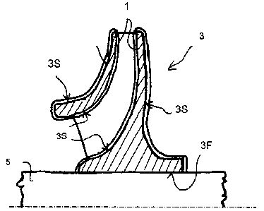
Fig. 2 shows a partial section, not drawn to scale, of a centrifugal impeller
3 for a
centrifugal compressor, coated with the above mentioned coating 1 as indicated
in the
invention and mounted on a shaft 5: please note that the surface 3S of the
impeller 3 is
both external and internal (internal channels), exception made for the hole 3F
in
which the shaft 5 is mounted.
In particular, the impeller 3 drawn in the picture is a three dimensional
closed impeller;
obviously the impeller could be of any other type, an open three dimensional
impeller
for example, or a closed two dimensional impeller or an open one or any other
type.
Please note that figures 1 and 2 and not drawn to scale and that the thickness
of layer
1 was drawn only for explanatory reasons.
Fig. 3 shows schematically a generic centrifugal compressor 10 which includes
a
stator box 12 inside of which the shaft 5 is free to rotate; the shaft rests
on a set of
bearings which offer support 14 and on which a series of centrifugal impellers
3 were
mounted. The impellers have been coated 1, and each one of them is mounted for
each
stage of the compressor 10. On the box stator channels were carved 16 which
allow
the process fluid to reach the exit of the first impeller towards the second
one of the
next stage and so on, until the fluid will exit the machinery from the
compressor 10.
Please note that this compressor is just an example, and that the invention
can be used
in another type of centrifugal compressor or in another centrifugal piece of
turbomachinery, such as a pump or an expander or other types of devices. To
lay the
protective coating 1 the procedure conveniently suggests immersing the
impeller 3 in
a process bath containing an aqueous solution of reagents.
The chemical baths contain at least the following reagents: nickel salts,
sodium
hypophosphite reducers mixed with an aqueous solution. The reaction is
triggered
spontaneously as soon as the impeller is immersed in the bath and slowly the
impeller
3 will start being covered with the thin layer 1 in nickel.
It is possible to set the thickness of the coating, preferably from 50 to up
to 100
microns or more, properly regulating the duration of the immersion of the
impeller in
the bath (once the deposition speed is known).
9
CA 02711121 2010-07-15
235238 (72NP)
It is also possible to apply more layers on the nickel one, such as paints or
resins or
other similar products depending on the specific application.
It is also possible to use specific elements or substances, such as tungsten
carbide,
DLC, chrome carbides, lactic acid or others, dissolved in the chemical bath
based on
the specific application.
It is possible to prepare the surface of the impeller 3 for the following
treatments
implementing a few preliminary treatments, such as shot peening to reduce the
tension
and enhance the strain resistance of the material; degreasing of the impeller
with
solvents or detergents or vapour or immersing the part to perform chemical
degreasing treatments; masking of areas of the surface which will not be
coated, for
example the hole in which the shaft will be mounted, or other treatments
thereof.
In the most convenient application of the invention, the light alloy which the
mechanical component 3 is made of is an aluminium based alloy.
The following tables indicate, as an example, the composition of the aluminium
alloys
7175-T74 and 7050-T7452 (following the definition of the international
regulations
ASTM B 247 M) which can be used to produce component 3; obviously this is just
an
example and the light alloy specifications can differ both in the percentages
and in the
components used.
Composition (ASTM B Min % Max %
247 M)
Aluminium Al 87.82 91.42
Chromium Cr 0.18 0.28
Copper Cu 1.20 2.00
Iron Fe 0.20
Magnesium Mg 2.10 2.90
Manganese Mn 0.30
Silicon Si 0.10
Titanium Ti 0.10
Zinc Zn 5.10 6.10
Others (each) 0.05
Others (Total) 0.15
Aluminium alloy 7175-T74
CA 02711121 2010-07-15
235238 (72NP)
Composition (ASTM B Min % Max %
247 M)
Aluminium Al Bal. Bal.
Chromium Cr - 0.04
Copper Cu 2.00 2.60
Iron Fe - 0.15
Magnesium Mg 1.90 2.60
Manganese Mn - 0.10
Silicon Si - 0.12
Titanium Ti - 0.06
Zinc Zn 5.70 6.70
Others (each) - 0.05
Aluminium alloy 7050-
T7452
Fig. 4 shows an explanatory graph of the results of some erosion tests
performed
following the standard indicated by the regulations ASTM D 968-93 on several
samples, in which: the X-axis indicates the quantity of sand used in litters
and the Y-
axis indicates the thickness of the eroded sample, based on normalised values
(where
100% indicates the maximum erosion value obtained in the test).
In particular, the line 4A shows the results of the test for a sample in an
alloy a in steel
without coating; line 4B shows a sample made of an aluminium based alloy
coated
with a layer as indicated in the invention; line 4C shows a sample in an
aluminium
based alloy coated with a layer of hard anodisation which is Typically used to
coat
aluminium and the fourth line 4D shows a sample of an aluminium based alloy
without coating.
Please note that in this graph the sample made of aluminium based alloy
without
coating, shows resistance values against erosion caused by solid particles
which is
significantly lower than the one of steel; please also note how, after the
application of
the coating, as indicated by the invention, it is possible to give the
aluminium a
resistance to erosion which is similar to the one of steel and much higher
than the hard
anodisation coating applied on aluminium to enhance hardness.
11
CA 02711121 2010-07-15
235238 (72NP)
It is agreed that the illustration is only an indication and that it does not,
in any way,
limit the possibilities of the invention, which can vary in form and ways
always being
pertinent to the foundation at the base of the invention itself. The possible
presence of
ref. numbers in the attached Claims has the only aim to make reading easier
both
when related to the previous text and when referring to the attached drawings,
and
does not limit, in any way, the scope of protection.
12