Note: Descriptions are shown in the official language in which they were submitted.
CA 02711175 2012-11-21
Docket No.: 1106-022 US01/ RCA-10720
SUBSTRATE FEATURES FOR MITIGATING STRESS
TECHNICAL FIELD
[0002] The disclosure is directed to techniques for mitigating stress
experienced by
an article that includes a coating layer.
BACKGROUND
[0003] The components of high-temperature mechanical systems, such as, for
example, gas-turbine engines, must operate in severe environments. For
example,
the combustor liners exposed to hot gases in commercial aeronautical engines
typically experience coating surface temperatures of up to about 1150 C to
about
1400 C.
[0004] Typical components of high-temperature mechanical systems include a Ni
or Co-based superalloy substrate. The substrate can be coated with a thermal
barrier coating (TBC) to reduce surface temperatures. The thermal barrier
coating
may include a thermally insulative ceramic topcoat, and may be bonded to the
substrate by an underlying metallic bond coat.
[0005] The component may be exposed to widely different temperatures during
operation and when operation is ceased. These widely different temperatures
may
cause significant thermal stress to the TBC, which eventually may lead to
spallation of the TBC from the substrate. The stress may be due to, for
example,
the substrate/bond coat and TBC having different coefficients of thermal
expansion, or the substrate/bond coat and TBC experiencing different
temperatures
due to thermal gradients.
1
CA 02711175 2010-07-16
Docket No.: 1106-022US01/ RCA-10720
SUMMARY
[0006] In general, the disclosure is directed to techniques for mitigating
stress
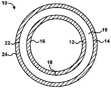
experienced by an article that includes a coating layer. In some examples, the
article is a blade airfoil that includes a tip that defines an edge. The
article may be
coated with a one or more coating layers to protect the airfoil from
environmental
conditions experienced by the airfoil during operation. Different forces
acting on
the airfoil during operation may have a tendency to promote detachment between
the underlying airfoil substrate and the one or more coating layers. In some
examples, forces may concentrate at an edge of the airfoil, causing crack
growth to
begin at the edge of the airfoil and propagate away from the edge. Over time,
the
different forces acting on the airfoil may lead to crack formation and growth
in the
one or more coating layers, thereby promoting delamination between the airfoil
and the one or more coating layers. The present disclosure provides techniques
for
mitigating crack propagation and detachment of a coating layer from an
underlying
substrate.
[0007] In some examples, the article may be coated with a thermal barrier
coating
(TBC). For example, an article may be coated with a TBC that includes a
thermally insulative layer. The thermally insulative layer is bonded to the
substrate
by a metallic bond coat. In some embodiments, the substrate/bond coat and the
thermally insulative layer may have different coefficients of thermal
expansion and
thus undergo different amounts of thermal expansion and/or contraction when a
temperature of the article changes. In addition, because the TBC insulates the
substrate, the substrate and TBC may experience different temperatures, which
may further affect the relative amounts of expansion and/or contraction
experienced by the substrate and TBC. This may lead to mechanical stress at or
above the bond coat/TBC interface, which over time may lead to crack formation
and growth in the TBC. Eventually, when the crack grows to a sufficient size,
the
TBC may detach from the substrate. This may leave an area of the substrate or
bond coat exposed to elevated temperatures that may be harmful to the
substrate or
bond coat.
2
CA 02711175 2010-07-16
Docket No.: 1106-022US0 I/ RCA-10720
[0008] In one aspect, the disclosure is directed to an article including a
substrate, at
least one cooling hole formed in the substrate, an array of features formed on
a
surface of the substrate, and a thermal barrier coating formed on the
substrate and
the first array of features. The array of features may be proximate to and
substantially aligned with the at least one cooling hole.
[0009] In another aspect, the disclosure is directed to an article including a
substrate and a first array of features on a surface of the substrate at a
first location.
The first array may comprise a first pattern. The article also includes a
second
array of features on the surface of the substrate at a second location. The
second
array may comprise a second pattern different than the first pattern. The
first
location may be predicted to experience a first level of thermal stress and
the
second location may be predicted to experience a second level of thermal
stress
different than the first level of thermal stress. The article further includes
a thermal
barrier coating formed on the substrate, the first array of features, and the
second
array of features.
[0010] In a further aspect, the disclosure is directed to a method including
forming
an array of features on a surface of a substrate and forming a thermal barrier
coating over the substrate and the array of features. The array of features
may be
proximate to and substantially aligned with at least one cooling hole formed
in the
substrate.
[0011] In an additional aspect, the disclosure is directed to a method
including
forming a first array of features on a surface of a substrate at a first
location. The
first location may be selected based on a first predicted level of thermal
stress, and
the first array of features comprises a first pattern. The method also
includes
forming a second array of features on the surface of the substrate at a second
location. The second location may be selected based on a second predicted
level of
thermal stress, and the second array of features comprises a second pattern
different than the first pattern. The method further includes forming a
thermal
barrier coating over the substrate, the first array of features, and the
second array of
features.
[0012] In another aspect, the disclosure is directed to an airfoil that
includes a tip
that defines an edge and an array of features formed on a surface of the tip.
The
3
CA 02711175 2010-07-16
Docket No.: 1106-0221JS01/ RCA-10720
array of features is proximate to the edge, and the array of features does not
intersect the edge. A coating layer is formed on the surface of the substrate
and the
array of features.
[0013] In another aspect, the disclosure is directed to an airfoil that
includes a tip
that defines an edge, a first array of features formed on a surface of the tip
at a first
location, and a second array of features formed on the surface of the tip at a
second
location. The first array includes a first pattern and the second array
includes a
second pattern different than the first pattern. The first location is
predicted to
experience a first level of stress and the second location is predicted to
experience
a second level of stress different than the first level of stress. The first
array of
features and the second array of features do not intersect the edge. The
airfoil
includes a coating layer on the tip, the first array of features, and the
second array
of features.
[0014] In another aspect, the disclosure is directed to a method that includes
forming an array of features on a tip surface of an airfoil that defines an
edge and
forming a coating layer on the tip surface and the array of features.
According to
the method, the array of features is proximate to the edge, and the array of
features
does not intersect the edge.
[0015] The details of one or more examples are set forth in the accompanying
drawings and the description below. Other features, objects, and advantages
will
be apparent from the description and drawings, and from the claims.
BRIEF DESCRIPTION OF DRAWINGS
[0016] FIGS. lA and 1B are cross-sectional diagrams of an exemplary gas
turbine
engine combustor liner.
[0017] FIGS. 2A-2D are cross-sectional diagrams illustrating exemplary cross-
sectional shapes of features formed in a substrate.
[0018] FIGS. 3A-3G are conceptual diagrams depicting exemplary substrates in
which cooling holes and examples of arrays of features substantially aligned
with
the cooling holes are formed.
[0019] FIG. 4 is a flow diagram of an exemplary technique of forming an
article
including a substrate, an array of features formed in the substrate and
substantially
4
CA 02711175 2010-07-16
Docket No.: 1106-022US01/ RCA-10720
aligned with cooling holes formed in the substrate, and a bond coat and
thermal
barrier coating formed on the substrate and the array of features.
[0020] FIG. 5 is a cross-sectional diagram of an exemplary article including a
thermal barrier coating comprising a first and a second thermally insulative
layer
formed on a substrate including features formed in a surface of the substrate.
[0021] FIG 6 is a cross-sectional diagram of an exemplary article including a
bond
coat and a thermal barrier coating a first thermally insulative layer
comprising a
plurality of substantially vertical cracks and a second thermally insulative
layer.
[0022] FIGS. 7A-7D are conceptual diagrams of exemplary substrates in which
first and second arrays of features are formed in first and second locations
of the
substrate, respectively.
[0023] FIG 8 is a cross-sectional diagram of an exemplary substrate that
includes
features formed with different sizes and depths.
[0024] FIG 9 is a flow diagram of an exemplary technique of forming an article
including a first array of features in a first location on a substrate and a
second
array of features in a second location on the substrate.
[0025] FIGS. 10A¨C are conceptual diagrams of an example blade airfoil
configured for use in a gas turbine engine.
[0026] FIGS. 11A¨C are cross-sectional diagrams of example airfoil surfaces
for
the example blade airfoil of FIGS. 10A¨C.
[0027] FIGS. 12A¨F are cross-sectional diagrams illustrating exemplary cross-
sectional shapes of features for the example airfoil surfaces of FIGS. 11A¨C.
[0028] FIGS. 13A-13G are conceptual diagrams depicting example blade tip
surfaces on which example arrays of features are formed.
[0029] FIGS. 14A-14C are conceptual diagrams illustrating example blade tips
with example arrays of features.
[0030] FIG. 15 is a flow diagram of an example technique of forming an article
including a substrate, an array of features formed in the substrate, and one
or more
coating layers formed on the substrate and the array of features.
[0031] FIGS. 16A-16D are conceptual diagrams of exemplary substrates in which
first and second arrays of features are formed in first and second locations
of the
substrate, respectively.
CA 02711175 2010-07-16
Docket No.: 1106-022U S01/ RCA-10720
[0032] FIG. 17 is a cross-sectional diagram of an example substrate that
includes
features formed with different sizes and depths.
[0033] FIG. 18 is a flow diagram of an example technique of forming an article
including a first array of features in a first location on a substrate and a
second
array of features in a second location on the substrate.
DETAILED DESCRIPTION
[0034] In general, the present disclosure is directed to techniques for
mitigating
thermal stress in an article coated with a thermal barrier coating (TBC) and
increasing the life span of the TBC. As described above, an article, such as a
gas
turbine engine combustor liner, may experience widely varying temperatures
during use. These changes in temperature may lead to thermal stress at an
interface between two layers having different coefficients of thermal
expansion.
For example, an article may be coated with a TBC that includes a bond coat
formed on a substrate of the article and a thermally insulative layer formed
on the
bond coat. In some embodiments, the substrate/bond coat and the thermally
insulative layer may have different coefficients of thermal expansion and thus
undergo different amounts of thermal expansion and/or contraction when a
temperature of the article changes. This may lead to mechanical stress at or
above
the interface of the bond coat and thermally insulative layer, which over time
may
lead to crack formation and growth in the thermally insulative layer.
Eventually,
when the crack grows to a sufficient size, the thermally insulative layer may
detach
from the substrate. This may leave an area of the substrate or bond exposed to
elevated temperatures that may be harmful to the substrate or bond coat.
[0035] Disclosed herein are techniques for minimizing the effect of crack
growth
in the thermally insulative layer. The techniques include forming features in
a
surface of the substrate. The features disrupt the relative planarity of the
surface
and impede crack growth or propagation. In particular, when a crack forms in
the
thermally insulative layer and begins to propagate in a plane substantially
parallel
to the surface of the substrate, the features serve as an impediment to
further crack
growth by presenting an interface between two materials, e.g., the thermally
insulative layer and the bond coat, across which the crack would be required
to
6
CA 02711175 2010-07-16
Docket No.: 1106-022U S01/ RCA-10720
grow. In effect, the features segregate the substrate and TBC into a plurality
of
smaller domains. Crack growth may occur within individual domains, but the
features hinder crack growth between adjacent domains.
[0036] In some embodiments, the features may be formed in the substrate
proximate to and substantially aligned with cooling holes formed in the
substrate.
Such an arrangement may improve thermal stress resistance of the article
compared to a substrate that does not include such features. For example, if
the
thermally insulative layer delaminates from a substrate domain, the proximity
of
the substrate domains to cooling holes may allow air flowing from the cooling
holes to provide some thermal protection to the exposed substrate. The cooling
holes may also improve thermal performance of the article when the thermally
insulative layer is intact and attached to the substrate.
[0037] In some embodiments, the features may be formed in a first array in a
first
location on the substrate and in a second array in a second location on the
substrate. The pattern of the first array and the pattern of the second array,
and the
first and second locations, may be selected based on a prediction of the
thermal
stress that the substrate will experience at the first location and the second
location,
respectively. For example, the substrate may experience higher temperatures or
more severe temperature changes at the first location and lower temperatures
or
less severe temperature changes at the second location. Based on this, the
pattern
of the first array of features may be selected to be different than the
pattern of the
second array of features. For example, the first array of features may include
features that are spaced more closely together, have a different shape, or
include
another characteristic that provides superior thermal stress mitigation than
the
second array of features. In some embodiments, the first and second arrays of
features each may be proximate to and substantially aligned with cooling holes
in
the substrate.
[0038] FIGS. IA and 1B are cross-sectional diagrams of a simplified example of
a
gas turbine engine combustor section 10 including an inner combustor liner 12
and
an outer combustor liner 14. Combustor section 10 may be a tiled combustor
section, in which a plurality of separate metal sheets are joined to form each
of
inner combustor liner 12 and outer combustor liner 14, or each of inner
combustor
7
CA 02711175 2010-07-16
Docket No.: 1106-022 U S01/ RCA-10720
liner 12 and outer combustor liner 14 may be formed of substantially a single
sheet
of metal. Inner combustor liner 12 defines an inner surface 16 and an outer
surface
18, and outer combustor liner 14 defines an inner surface 22 and an outer
surface
24. Inner combustor liner 12 and outer combustor liner 14 define a combustion
chamber 19 in the annulus between outer surface 18 and inner surface 22.
Substrate features may be formed according to the techniques of the present
disclosure on either or both of outer surface 18 of inner combustor liner 12
or inner
surface 22 of outer combustor liner 14. Although not shown in FIG. 1A, either
or
both of outer surface 18 of inner combustor liner 12 or inner surface 22 of
outer
combustor liner 14 may define a plurality of cooling holes 20.
[0039] As described above, gas turbine engine combustor section 10 may be a
component of a high temperature mechanical system, such as a gas turbine
engine.
When used in a high temperature mechanical system, inner combustor liner 12
and/or outer combustor liner 14 may experience high temperatures and/or large
temperature changes. Thus, outer surface 18 of inner combustor liner 12 and/or
inner surface 22 of outer combustor liner 14 may include a thermally
protective
coating formed on a substrate 26 (FIG. 1B). For example, substrate 26 may be
coated with a thermal barrier coating (TBC) 28, which includes a bond coat 30
and
a thermally insulative layer 32 that provides thermal insulation for outer
surface 18
of inner combustor liner 12, inner surface 22 of outer combustor liner 14, or
both.
[0040] Substrate 26 may comprise, for example, a superalloy based on Ni, Co,
Ni/Fe, or the like. A substrate 26 including a superalloy may include other
additive elements to alter its mechanical properties, such as toughness,
hardness,
temperature stability, corrosion resistance, oxidation resistance, and the
like, as is
well known in the art. In some embodiments, substrate 26 may include at least
one
of Cr, Mo, Ta, B, C, Co, Al, Hf, Re, or the like. Any useful superalloy may be
utilized for substrate 26, including, for example, those available from Haynes
International, Kokomo, IN, under the trade designations Haynes 230 and
Hastelloy X , and the like.
[0041] Bond coat 30 may be formed on substrate 26, and may increase adhesion
between substrate 26 and thermally insulative layer 32. Bond coat 30 may
include
an alloy, such as a MCrA1X alloy (where M is Ni, Co, or NiCo, and X is Y, Hf,
Ce,
8
CA 02711175 2010-07-16
Docket No.: 1106-022US01/ RCA-10720
La, Si, or combinations thereof). In some embodiments bond coat 30 may include
a MCrAIX alloy modified by Pt, another precious metal group element, or a
refractory metal.
[0042] Bond coat 30 may be formed on substrate by, for example, a thermal
spraying technique, such as air plasma spraying (APS), low pressure plasma
spraying (LPPS), high velocity oxy-fuel spraying (HVOF), electroplating, or
the
like.
[0043] Although not shown in FIG. 1B, radially inward combustion liner 12 or
radially outward combustor liner 14 may sometimes include a thermally grown
oxide (TGO) formed on bond coat 30. In some embodiments, the TGO may be
formed by oxidizing bond coat 30. For example, bond coat 30 may be heated in
an
oxidizing atmosphere during service to grow the TGO on bond coat 30. In many
embodiments, the TGO comprises alumina (A1203), along with other elements
diffused from bond coat 30 or substrate 26.
[0044] Thermally insulative layer 32 may provide thermal protection
(insulation)
to substrate 26. Thermally insulative layer 32 may comprise at least one of a
variety of materials, including, for example, yftria-stabilized zirconia,
yttria-
stabilized hafnia, a rare earth oxide, a rare earth oxide-stabilized zirconia,
a rare
earth oxide-stabilized hafnia, a silicate, a zirconate, an aluminate, or
combinations
thereof.
[0045] Yttria-stabilized zirconia includes zirconia (Zr02) mixed with a
minority
amount of yttrium oxide (Y203). For example, one yttria-stabilized zirconia
composition includes zirconia stabilized by about 7 wt. % to about 8 wt. %
yttrium
oxide. In some embodiments, yttria-stabilized zirconia may further include
another rare earth oxide.
[0046] Rare earth oxides used in thermally insulative layer 32 include, for
example, oxides of lutetium (Lu), ytterbium (Yb), thulium (Tm), erbium (Er),
holmium (Ho), dysprosium (Dy), gadolinium (Gd), terbium (Tb), europium (Eu),
samarium (Sm), promethium (Pm), neodymium (Nd), praseodymium (Pr), cerium
(Ce), lanthanum (La), yttrium (Y), scandium (Sc), and combinations thereof.
The
same rare earth elements may also be useful when present as rare earth
silicates,
rare earth aluminates, or rare earth zirconates.
9
CA 02711175 2010-07-16
Docket No.: 1106-022U S01/ RCA-10720
[0047] In the embodiment illustrated in FIG. 1B, substrate 26 includes four
features 34a, 34b, 34c, and 34d (collectively "features 34") formed in a
surface 36
of substrate 26. Features 34 may comprise depressions formed in surface 36,
and
may be formed by, for example, chemical etching, photolithography, laser
machining, electrochemical machining, electro-discharge machining,
micromachining, vibropeening, or the like.
[0048] Each of the features 34 disrupts the relative planarity of surface 36,
e.g.,
each of features 34 may form a discontinuity in surface 36. Features 34 may
impede crack growth in thermally insulative layer 32 in a plane parallel to
surface
36. While not wishing to be bound by any particular theory, features 34 may
result
in an interface between bond coat 30 and thermally insulative layer 32 across
which a crack would need to propagate to grow from a portion of thermally
insulative layer 32 located in a feature 34 to a portion of thermally
insulative layer
32 located on a plateau of surface 36. The transition between dissimilar
materials,
e.g., bond coat 30 and thermally insulative layer 32, may impede crack growth
across the interface of the two materials, and may contain crack growth to a
single
domain, e.g., a portion of thermally insulative layer 32 located in a feature
34 or a
portion of thermally insulative layer 32 located on a plateau of surface 36.
Accordingly, even if a crack grows to the extent that a portion of TBC 28
delaminates from substrate 26, the portion of TBC 28 that delaminates may be
limited to a portion above a feature 34 or a portion above a plateau of
surface 36.
[0049] Features 34 may include, for example, depressions in surface 36, as
shown
in FIG. 1B. Features 34 may include a generally rectangular cross-section 38,
as
shown in FIG. 1B, or may include another cross-sectional profile. For example,
as
shown in FIG. 2A, a feature 34e may include a generally arcuate cross-section
42,
such as a half-circle or another, lesser, portion of a circle. In other
examples, as
shown in FIGS. 2B-2D, a feature 34f may include a generally triangular cross-
section 44, a feature 34g may include a generally trapezoidal cross-section
46, or a
feature 34h may include a truncated arcuate cross-section 48. Such cross-
sectional
profiles are merely examples; other cross-sectional profiles are also possible
and
will be apparent to those of ordinary skill in the art.
CA 02711175 2010-07-16
Docket No.: 1106-022US01/ RCA-10720
[0050] As shown in FIG. 1B, features 34 may be formed proximate to at least
one
of cooling holes 20. Such an arrangement may provide an additional measure of
thermal protection to substrate 26. For example, should a portion of TBC 28
delaminate due to thermal stress-initiated crack growth, the portion may be
limited
to a portion above a feature 34 or a portion above a plateau of substrate 26,
as
described above. In addition, because features 34 are formed proximate to
cooling
holes 20 the portion of substrate 26 or bond coat 30 that was protected by the
now
delaminated portion of TBC 28 may be cooled by air exiting one or more
proximate cooling holes 20. This may provide thermal protection to the exposed
portion of substrate 26 or bond coat 30 after delamination of the portion of
TBC
28, which otherwise would not be possible if features 34 were not formed
proximate to cooling holes 20. Cooling holes 20 may also help to cool
substrate 26
when TBC 28 is substantially intact and attached to substrate 26.
[0051] Features 34 may be formed in an array comprising a plurality of
features
34. FIGS. 3A-3F illustrate a number of exemplary features 34 and arrays of
features 34. For example, FIG. 3A shows an array of features 52 including a
plurality of grooves 54. Grooves 54 are oriented substantially parallel to
each
other and are formed in substrate 26 proximate to cooling holes 20. In
addition,
grooves 54 are substantially aligned to cooling holes 20. In other words, in
the
embodiment illustrated in FIG. 3A, grooves are located between rows of cooling
holes 20, and are approximately equidistant from the row of cooling holes 20
on
either side of a respective one of grooves 54. Such an arrangement may
segregate
substrate 26 into a plurality of domains, each domain being located between
adjacent grooves. As described above, this may improve thermal stress
resistance
of TBC 28 formed on substrate 26.
[0052] In some embodiments, grooves 54 may be approximately the same width
W, as shown in FIG. 3A. In other embodiments, one or more grooves 54 may be a
different width W than other grooves 54. In some embodiments, a width W of
each of grooves 54 may be between approximately 0.005 inches and approximately
0.125 inches. In other embodiments, the width W of each of grooves 54 may be
between approximately 0.010 inches and approximately 0.050 inches.
11
CA 02711175 2010-07-16
Docket No.: 1106-022US01/ RCA-10720
[0053] Adjacent grooves 54 may be spaced approximately evenly apart, or may be
spaced different distances apart. The distance D between adjacent grooves 54
may
be referred to as pitch, and in some embodiments, may vary between
approximately 0.2 inches and approximately 0.3 inches. In some embodiments,
the
pitch may increase or decrease monotonically. In other embodiments, the pitch
may increase and then decrease or may decrease and then increase. In yet other
embodiments, as illustrated in FIG. 3A, the pitch may be approximately
constant.
[0054] Grooves 54 may have a variety of cross-sectional shapes, including, for
example, an arcuate, truncated arcuate, rectangular, trapezoidal, or
triangular cross-
section, as illustrated in FIGS. 1B and 2A-2D. Each of grooves 54 may have the
same cross-sectional profile, or at least one of grooves 54 may have a
different
cross-sectional profile than another one of grooves 54. The depth of each of
grooves 54 may be between approximately 0.004 inches and approximately 0.020
inches. In some embodiments, the depth of each of grooves 54 may be between
approximately 0.004 inches and approximately 0.008 inches. Similar to the
width
W, the depth of each of grooves 54 may be approximately the same or the depth
of
at least one of grooves 54 may be different than at least one other of grooves
54.
The depth of grooves 54 may substantially similar, may increase or decrease
monotonically, may increase and then decrease, or may decrease and then
increase.
[0055] FIG. 3B illustrates an example of an array of features 56 that includes
a
grid 58 formed by a first plurality of grooves formed substantially parallel
to each
other and a second plurality of grooves formed substantially parallel to each
other
and substantially perpendicular to the first plurality of grooves. Grid 58
forms a
depression in substrate 26 and defines a plurality of plateaus 59 in substrate
26. A
respective one of cooling holes 20 is formed in each of plateaus 59. In this
way,
grid 58 segregates substrate 26 into a plurality of domains and impedes cracks
from growing from one domain to an adjacent domain. Array of features 56 is
formed proximate to and substantially aligned with cooling holes 20.
[0056] In some embodiments, each of the grooves oriented substantially
horizontally in FIG. 3B may have a first width WI, and each of the grooves
oriented substantially vertically in FIG. 3B may have a second width W2. In
some
embodiments, first width WI may be the same as second width W2, while in other
12
CA 02711175 2010-07-16
Docket No.: 1106-022US01/ RCA-10720
embodiments first width W1 may be different than second width W2. In addition,
in some embodiments the width of at least one vertically oriented groove in
grid 58
may be different than the width of another vertically oriented groove in grid
58.
Similarly, the width of at least one horizontally oriented groove in grid 58
may be
different than the width of another horizontally oriented groove in grid 58.
In
some embodiments, the width of horizontally or vertically oriented grooves in
grid
58 may increase or decrease monotonically, while in other embodiments, the
width
of horizontally or vertically oriented grooves in grid 58 may increase and
then
decrease or decrease and then increase. The width (W1 or W2) of each of the
grooves in grid 58 may be between approximately 0.005 inches and approximately
0.125 inches. In other embodiments, the width (W1 or W2) of each of the
grooves
in grid 58 may be between approximately 0.010 inches and approximately 0.050
inches.
[0057] Adjacent parallel grooves in grid 58 may be spaced approximately evenly
apart, or may be spaced different distances apart. In some embodiments, the
distance DI or D2 between adjacent grooves 54 may vary between approximately
0.2 inches and approximately 0.3 inches. In some embodiments, the pitch may
increase or decrease monotonically. In other embodiments, the pitch may
increase
and then decrease or may decrease and then increase. In yet other embodiments,
as
illustrated in FIG. 3B, the pitch may be approximately constant. In addition,
in
some embodiments the distance DI between adjacent grooves in a first direction
may be different than the distance D2 between adjacent grooves in a second
direction. In some examples, the pitch in one direction may increase or
decrease
within grid 58, while the pitch in a second direction may be approximately
constant.
[0058] Each of the grooves in grid 58 may have one of a variety of cross-
sectional
shapes, including, for example, an arcuate, truncated arcuate, rectangular,
trapezoidal, or triangular cross-section, as illustrated in FIGS. 1B and 2A-
2D.
Each of the grooves in grid 58 may have the same cross-sectional profile, or
at
least one of the grooves in grid 58 may have a different cross-sectional
profile than
another one of the grooves in grid 58. The depth of each of the grooves may be
between approximately 0.004 inches and approximately 0.020 inches. In some
13
CA 02711175 2010-07-16
Docket No.: 1106-022US01/ RCA-10720
embodiments, the depth of each of the grooves may be between approximately
0.004 inches and approximately 0.008 inches. Similar to the width W, the depth
of
each of the grooves in grid 58 may be approximately the same or the depth of
at
least one of the grooves may be different than at least one other of the
grooves.
The depth of the grooves may increase or decrease monotonically, or may
increase
and then decrease or decrease and then increase. In some examples, the depth
of
the grooves oriented in a first direction, e.g., vertically in FIG. 3B, may be
different than the depth of the grooves oriented in a second direction, e.g.,
horizontally in FIG. 3B. In addition, the depth of the grooves oriented in one
direction may change within grid 58, while the depth of grooves oriented in a
second direction within grid 58 may be approximately constant.
[0059] In other embodiments, as illustrated in FIG. 3C, an array of features
60 may
include a grid of sinusoidal grooves 62. Grid 62 forms a depression in
substrate 26
and defines a plurality of plateaus 59 in substrate 26. A respective one of
cooling
holes 20 is formed in each of plateaus 59. In this way, grid 62 segregates
substrate
26 into a plurality of domains and impedes cracks from growing from one domain
to an adjacent domain. Array of features 60 is formed proximate to and
substantially aligned with cooling holes 20.
[0060] As described above, each of the grooves oriented in a first direction
may
have a first width WI, and each of the grooves oriented in a second direction
may
have a second width W2. In some embodiments, first width W1 may be the same
as second width W2, while in other embodiments first width W1 may be different
than second width W2. In addition, in some embodiments the width of at least
one
groove oriented in a first direction in grid 62 may be the same as or
different than
the width of another groove oriented in the first direction in grid 62. In
some
embodiments, the width of grooves oriented in a single direction in grid 62
may
increase or decrease monotonically, while in other embodiments, the width of
grooves oriented in a single direction in grid 62 may increase and then
decrease or
decrease and then increase. The width (W1 or W2) of each of the grooves in
grid
62 may be between approximately 0.005 inches and approximately 0.125 inches.
In other embodiments, the width (W1 or W2) of each of the grooves in grid 62
may
be between approximately 0.010 inches and approximately 0.050 inches.
14
CA 02711175 2010-07-16
Docket No.: 1106-022US01/ RCA-10720
[0061] Adjacent parallel grooves in grid 62 may be spaced approximately evenly
apart, or may be spaced different distances apart, similar to the grooves in
grid 58
illustrated in FIG. 3B. In some embodiments, the distance D1 or D2 between
adjacent grooves 54 may vary between approximately 0.2 inches and
approximately 0.3 inches. The pitch may increase or decrease monotonically,
may
increase and then decrease, may decrease and then increase, or may be
approximately constant. In addition, the distance D1 between adjacent grooves
oriented in a first direction may be different than the distance D2 between
adjacent
grooves oriented in a second direction. In some examples, the pitch in one
direction may increase or decrease within grid 62, while the pitch in a second
direction may be approximately constant.
[0062] The amplitude, e.g., the distance from line 63 to a peak of groove 61,
of the
sinusoidal grooves in grid 62 may vary, and in some embodiments, may be
between approximately 0.2 inches and approximately 0.3 inches. In other
embodiments, the amplitude may be less than 0.2 inches or greater than
approximately 0.3 inches.
100631 Each of the grooves in grid 62 may have one of a variety of cross-
sectional
shapes, including, for example, an arcuate, truncated arcuate, rectangular,
trapezoidal, or triangular cross-section, as illustrated in FIGS. 1B and 2A-
2D. The
cross-sectional profiles of each of the grooves may be the same, or may be
different. The depth of each of the grooves may be between approximately 0.004
inches and approximately 0.020 inches. In some embodiments, the depth of each
of the grooves may be between approximately 0.004 inches and approximately
0.008 inches. In addition, the depth of each of the grooves in grid 62 may be
approximately the same or the depth of at least one of the grooves may be
different
than at least one other of the grooves. The depth of the grooves may increase
or
decrease monotonically, may increase and then decrease, or decrease and then
increase. In some examples, the depth of the grooves oriented in a first
direction
may be different than the depth of the grooves oriented in a second direction.
In
addition, the depth of the grooves oriented in one direction may change within
grid
62, while the depth of grooves oriented in a second direction within grid 62
may be
approximately constant.
CA 02711175 2010-07-16
Docket No.: 1106-022US01/ RCA-10720
[0064] In some embodiments, a substrate may include an array of discrete
features
instead of an array of substantially continuous features. For example, FIG. 3D
illustrates an array of features 64 that includes a plurality of circular
depressions 66
formed in substrate 26. Similarly, FIG. 3E illustrates an array of features 68
that
includes a plurality of hexagonal depressions 70 formed in substrate 26 and
FIG.
3F illustrates an array of features 72 that includes a plurality of elliptical
depressions 74 formed in substrate 26. The plurality of circular depressions
66
may be formed proximate to cooling holes 20. Circular depressions 66 are also
substantially aligned with cooling holes 20, forming a pattern of rows of
depressions 66 between adjacent rows of cooling holes 20.
[0065] As shown in FIGS. 3E and 3F, the plurality of hexagonal depressions 70
and plurality of elliptical depressions 74 form different patterns around
cooling
holes 20 than the plurality of circular depressions 66. Regardless of the
particular
pattern formed by circular, hexagonal, and elliptical depressions 66, 70, or
74
(collectively "depressions 66"), the depressions 66 are each formed proximate
to
and substantially aligned with cooling holes 20. The illustrated patterns and
shapes
of depressions 66 are merely examples, and other patterns and shapes of
depressions 66 are contemplated. In addition, an array of features may include
depressions 66 of different shapes, such as circular, hexagonal, or elliptical
shapes
(see FIG. 7D).
[0066] As described above, each of depressions 66 may have a diameter or width
W. In some embodiments, the diameter or width W of depressions 66 may
increase or decrease monotonically, while in other embodiments, the diameter
or
width W of depressions 66 may increase and then decrease or decrease and then
increase. In other embodiments, the diameter or width W of depressions 66 may
be substantially similar throughout array of features 64. In some embodiments,
the
diameter or width W of each of depressions 66 may be between approximately
0.005 inches and approximately 0.125 inches. In other embodiments, the
diameter
or width W of each of depressions 66 may be between approximately 0.010 inches
and approximately 0.050 inches.
[0067] Depressions 66 may be spaced approximately evenly apart, or may be
spaced different distances apart, similar to the grooves in grid 58
illustrated in FIG.
16
CA 02711175 2010-07-16
Docket No.: 1106-022US01/ RCA-10720
3B. The distance D between adjacent depressions 66 may vary in some
embodiments between approximately 0.2 inches and approximately 0.3 inches.
The pitch may increase or decrease monotonically, may increase and then
decrease, may decrease and then increase, or may be approximately constant. In
addition, the distance D between adjacent depressions 66 in a first direction
may be
different than the distance D between adjacent depressions 66 in a second
direction. In some examples, the pitch in one direction may increase or
decrease,
while the pitch in a second direction may be approximately constant. In other
examples, the pitch in two substantially perpendicular directions may each
change,
e.g., increase in both directions, decrease in both directions, or increase in
a first
direction and decrease in a second direction.
[0068] Each of depressions 66 may have one of a variety of cross-sectional
shapes,
including, for example, an arcuate, truncated arcuate, rectangular,
trapezoidal, or
triangular cross-section, as illustrated in FIGS. 1B and 2A-2D. The cross-
sectional profiles of each of depressions 66 may be the same or may be
different
within an array of features 64, 68, or 72. The depth of each of depressions 66
may
be between approximately 0.004 inches and approximately 0.020 inches. In some
embodiments, the depth of each of depressions 66 may be between approximately
0.004 inches and approximately 0.008 inches. In addition, the depth of
depressions
66 within an array of features 64, 68, or 72 may be approximately the same or
the
depth of at least one of the depressions 66 may be different than at least one
other
of the depressions 66. The depth of the depressions 66 may increase or
decrease
monotonically, may increase and then decrease, or decrease and then increase.
In
addition, the depth of the depressions 66 may change along one direction
within an
array of features 64, 68, or 72, while the depth of depressions 66 may or may
not
change along a second, substantially perpendicular direction within the array
of
features 64, 68, or 72.
[0069] Although substantially continuous features, such as grooves 54, and
discrete features, such as circular depressions 66, have been described
separately,
in some embodiments, continuous and discrete features may be utilized
together.
For example, FIG. 3G shows an array of features 76 including a plurality of
grooves 54 and a plurality of circular depressions 66. Grooves 54 are oriented
17
CA 02711175 2010-07-16
Docket No.: 1106-022USO I/ RCA-10720
substantially parallel to each other and are formed in substrate 26 proximate
to
cooling holes 20. In addition, grooves 54 are substantially aligned to cooling
holes
20. In other words, in the embodiment illustrated in FIG. 3G, grooves are
located
between rows of cooling holes 20, and are approximately equidistant from the
row
of cooling holes 20 on either side of a respective one of grooves 54. Such an
arrangement may segregate substrate 26 into a plurality of domains, each
domain
being located between adjacent grooves. As described above, this may improve
thermal stress resistance of TBC 28 formed on substrate 26.
[0070] In some embodiments, grooves 54 may be approximately the same width
W2, as shown in FIG. 3G. In other embodiments, one or more grooves 54 may be
a different width W2 than other grooves 54. In some embodiments, a width W2 of
each of grooves 54 may be between approximately 0.005 inches and approximately
0.125 inches. In other embodiments, the width W2 of each of grooves 54 may be
between approximately 0.010 inches and approximately 0.050 inches.
[0071] Adjacent grooves 54 may be spaced approximately evenly apart, or may be
spaced different distances apart. The distance D2 between adjacent grooves 54
may be referred to as pitch, and in some embodiments, may vary between
approximately 0.2 inches and approximately 0.3 inches. In some embodiments,
the
pitch may increase or decrease monotonically. In other embodiments, the pitch
may increase and then decrease or may decrease and then increase. In yet other
embodiments, as illustrated in FIG. 3G, the pitch may be approximately
constant.
[0072] Grooves 54 may have one or more of a variety of cross-sectional shapes,
including, for example, an arcuate, truncated arcuate, rectangular,
trapezoidal, or
triangular cross-section, as illustrated in FIGS. 1B and 2A-2D. Each of
grooves
54 may have the same cross-sectional profile, or at least one of grooves 54
may
have a different cross-sectional profile than another one of grooves 54. The
depth
of each of grooves 54 may be between approximately 0.004 inches and
approximately 0.020 inches. In some embodiments, the depth of each of grooves
54 may be between approximately 0.004 inches and approximately 0.008 inches.
Similar to the width W, the depth of each of grooves 54 may be approximately
the
same or the depth of at least one of grooves 54 may be different than at least
one
18
CA 02711175 2010-07-16
Docket No.: 1106-022US01/ RCA- 10720
other of grooves 54. The depth of grooves 54 may increase or decrease
monotonically, may increase and then decrease, or decrease and then increase.
[0073] The plurality of circular depressions 66 may be formed proximate to
cooling holes 20. Circular depressions 66 are also substantially aligned with
cooling holes 20, forming a pattern of rows of depressions 66 interspersed in
rows
of cooling holes 20.
[0074] Each of circular depressions 66 may have a diameter or width WI, which
may be the same as or different than width W2 of grooves 54. In various
embodiments, the diameter or width W1 of each of circular depressions 66 may
be
substantially similar, the diameter or width WI of circular depressions 66 may
increase or decrease monotonically, or the diameter or width W I of circular
depressions 66 may increase and then decrease or decrease and then increase.
The
diameter or width WI of each of circular depressions 66 may be between
approximately 0.005 inches and approximately 0.125 inches. In other
embodiments, the diameter or width W1 of each of circular depressions 66 may
be
between approximately 0.010 inches and approximately 0.050 inches.
[0075] Circular depressions 66 may be spaced approximately evenly apart, or
may
be spaced different distances apart, similar to the grooves in grid 58
illustrated in
FIG. 3B. The distance D1 between adjacent circular depressions 66 may vary in
some embodiments between approximately 0.2 inches and approximately 0.3
inches. The pitch may increase or decrease monotonically, may increase and
then
decrease, may decrease and then increase, or may be approximately constant. In
addition, the distance D1 between adjacent circular depressions 66 in a first
direction may be the same as or different than the distance D1 between
adjacent
circular depressions 66 in a second direction. In some examples, the pitch in
one
direction may increase or decrease, while the pitch in a second direction may
be
approximately constant. In other examples, the pitch in two substantially
perpendicular directions may each change, e.g., increase in both directions,
decrease in both directions, or increase in a first direction and decrease in
a second
direction.
[0076] Each of circular depressions 66 may have one of a variety of cross-
sectional shapes, including, for example, an arcuate, truncated arcuate,
rectangular,
19
CA 02711175 2010-07-16
Docket No.: 1106-022US01/ RCA-10720
trapezoidal, or triangular cross-section, as illustrated in FIGS. 1B and 2A-
2D. The
cross-sectional profiles of each of circular depressions 66 may be the same as
or
different than the cross-sectional profiles of grooves 54, and may be the same
or
may be different within array of features 76. The depth of each of circular
depressions 66 may be between approximately 0.004 inches and approximately
0.020 inches. In some embodiments, the depth of each of circular depressions
66
may be between approximately 0.004 inches and approximately 0.008 inches. In
addition, the depth of circular depressions 66 within array of features 76 may
be
approximately the same or the depth of at least one of the circular
depressions 66
may be different than at least one other of the circular depressions 66. The
depth
of the circular depressions 66 may increase or decrease monotonically, may
increase and then decrease, or decrease and then increase. In addition, the
depth of
the circular depressions 66 may change along one direction within array of
features
76, while the depth of circular depressions 66 may or may not change along a
second, substantially perpendicular direction within array of features 76.
[0077] FIG. 4 is a flow diagram of an exemplary technique of forming an
article
including a substrate having a plurality of features formed therein and a TBC
formed on the substrate. For the sake of clarity, the technique of FIG. 4 will
be
described with reference to gas turbine engine combustor section 10 shown in
FIGS. IA and 1B, but it will be understood that the technique of FIG. 4 may be
utilized on another component of a high temperature mechanical system, such
as,
for example, a turbine blade track, a turbine seal segment, an airfoil, or the
like.
[0078] Initially, an array of features 34 is formed in substrate 26 (82). The
array
may include a plurality of features 34, which may be formed proximate to and
substantially aligned with cooling holes 20 formed in substrate 26. The
features 34
may include, for example, linear grooves or sinusoidal grooves, a grid formed
by
linear or sinusoidal grooves, circular depressions, hexagonal depressions,
elliptical
depressions, or combinations of these features 34. The features may be formed
by,
for example, chemical etching, photolithography, laser machining,
electrochemical
machining, electro-discharge machining, micromachining, vibropeening, or the
like. In chemical etching and photolithography, portions of substrate 26 are
exposed to a chemical that reacts with substrate 26 to remove material from
CA 02711175 2010-07-16
Docket No.: 1106-022US01/ RCA-10720
substrate 26. By controlling the locations that are etched by the chemical and
the
amount of time for which substrate 26 is exposed to the chemical, the depth
and
shape of the features 34 may be controlled. The locations that are etched may
be
controlled by covering portions of substrate 26 that are not to be etched with
a
layer of material that is inert with respect to the chemical etchant.
[0079] In laser machining, a source of electromagnetic energy, such as an
excimer
laser, is used to generate a series of electromagnetic pulses of a wavelength
that is
absorbed by substrate 26. The intensity of the pulses is sufficient to cause
portions
of substrate 26 that absorb the energy to vaporize. Sequential exposure of
different
portions of substrate 26 may be used to vaporize substrate 26 and form
features 34.
[0080] Other methods of forming features 34 may include mechanical removal of
portions of substrate 26 by, for example, a pressurized stream of water, an
abrasive, water carrying an abrasive, or a tool that is sufficiently hard to
deform
substrate 26 or remove material from substrate 26.
[0081] Once the array of features 34 is formed in the substrate 26 (82), a
bond coat
30 may be deposited on substrate 26, including the array of features 34 (84).
As
described above, bond coat 30 may include an alloy, such as an MCrA1X alloy,
which may or may not be modified by inclusion of Pt, another precious metal
group element, or a refractory element.
[0082] Bond coat 30 may be formed on substrate by, for example, a thermal
spraying technique, such as air plasma spraying (APS), low pressure plasma
spraying (LPPS), high velocity oxy-fuel spraying (HVOF), electroplating, or
the
like. Bond coat 30 may be formed to a thickness between approximately 0.003
inches and approximately 0.020 inches. In some embodiments, bond coat 30 may
include a thickness between approximately 0.003 inches and 0.008 inches. Bond
coat 30 may substantially reproduce the geometry of substrate 26, including
features 34.
[0083] After formation of bond coat 30, thermally insulative layer 32 may be
formed on bond coat 30 (86). Thermally insulative layer 32 may comprise at
least
one of a variety of materials, including, for example, yttria-stabilized
zirconia,
yttria-stabilized hafnia, a rare earth oxide, a rare earth oxide-stabilized
zirconia, a
rare earth oxide-stabilized hafnia, a silicate, a zirconate, an aluminate, or
21
CA 02711175 2010-07-16
Docket No.: 1106-022US01/ RCA-10720
combinations thereof. Thermally insulative layer 32 may be formed by plasma
spraying.
100841 Thermally insulative layer 32 may be formed as a porous layer, with a
porosity ranging from approximately 5% to approximately 40%. The porosity of
thermally insulative layer 32 may reduce heat transfer compared to a non-
porous
thermally insulative layer 32. In some embodiments, thermally insulative layer
32
may be formed over bond coat 30 using plasma-spraying. The thickness of
thermally insulative layer 32 may range from approximately 0.005 inches and
approximately 0.04 inches. In some embodiments, the thickness of thermally
insulative layer 32 may range from approximately 0.005 inches to approximately
0.02 inches.
100851 In some embodiments, forming a thermally insulative layer 32 on bond
coat
30 (86) may include forming a first thermally insulative layer and a second
thermally insulative layer. For example, FIG. 5 shows an article 90 including
a
substrate 26, a bond coat 30 formed on substrate 26, a first thermally
insulative
layer 92 formed on bond coat 30, and a second thermally insulative layer 94
formed on first thermally insulative layer 92.
100861 First and second thermally insulative layers 92 and 94 may be formed
with
different porosities. For example, first thermally insulative layer 92 may be
formed with a porosity ranging between 5% and 25%, preferably between 5% and
15%. Second thermally insulative layer 94 may be formed with a porosity
between
5% and 40%, preferably between 5% and 20%. In some embodiments, the
porosity of the first and second thermally insulative layers 92 and 94 may be
approximately the same, and in other embodiments, the porosity of the first
and
second thermally insulative layers 92 and 94 may be different.
100871 In some embodiments, first thermally insulative layer 92 may comprise a
first material and second thermally insulative layer 94 may comprise a second
material. The first and second materials may be different, and may be selected
to
provide desired properties. For example, the first material may be selected to
have
a coefficient of thermal expansion that more closely matches the coefficient
of
thermal expansion of substrate 26 or bond coat 30, while the second material
has a
coefficient of thermal expansion that is not as similar to the coefficient of
thermal
22
CA 02711175 2010-07-16
Docket No.: 1106-022US01/ RCA-10720
expansion of substrate 26. In other embodiments, first thermally insulative
layer
92 and second thermally insulative layer 94 may include the same materials.
[0088] Each of first thermally insulative layer 92 and second thermally
insulative
layer 94 may be formed to a thickness between approximately 0.001 inches and
0.02 inches. In some embodiments, each of first and second thermally
insulative
layers 92 and 94 may be formed to thicknesses between 0.001 inches and 0.01
inches. First and second thermally insulative layers 92 and 94 may comprise
similar thicknesses or different thicknesses.
[0089] In some embodiments, as illustrated in FIG. 6, first thermally
insulative
layer 92 may be formed with a plurality of substantially vertical cracks 102,
e.g.,
cracks oriented substantially normal to surface 36 of substrate 26. The
plurality of
substantially vertical cracks 102 may further contribute to thermal stress
tolerance.
While not wishing to be bound by any particular theory, substantially vertical
cracks 102 may improve mechanical compliance of first thermally insulative
layer
92 compared to a first thermally insulative layer 92 that does not include
substantially vertical cracks 102. Substantially vertical cracks 102 may
facilitate
relative motion between adjacent domains 104a and 104b (collectively "domains
104") of first insulative layer 92, for example, during expansion and/or
contraction
of bond coat 30 and first thermally insulative layer 92 due to temperature
changes.
This may lower the out-of-plane stress due to a thermal expansion mismatch
across
the interface of bond coat 30 and first thermally insulative layer 92, and may
improve thermal stress tolerance of bond coat 98.
[0090] Substantially vertical cracks 102 may be formed in first thermally
insulative layer 92 during deposition of first thermally insulative layer 92
on bond
coat 30. For example, when first thermally insulative layer 92 is deposited
using
plasma spraying, first thermally insulative layer 92 may be heated to a high
temperature and cooled rapidly to thermally shock layer 92 and form
substantially
vertical cracks 102. As another example, substantially vertical cracks 102 may
be
formed by depositing first thermally insulative layer 92 in relatively thick
layers,
which builds stress in first thermally insulative layer 92. This stress
buildup may
result in formation of substantially vertical cracks 102, which release the
stress. In
other examples, first thermally insulative layer 92 may be formed of a
plurality of
23
CA 02711175 2010-07-16
Docket No.: 1106-022US01/ RCA-10720
sub-layers in which adjacent layers microweld to each other during plasma
deposition and grow substantially continuous vertical grains with
substantially
vertical cracks 102 formed between the grains.
[0091] FIG. 6 also illustrates features 34a, 34b, and 34c including rounded
edges
106. Rounded edges 106 may also act to mitigate effects of stress induced by
thermal cycling of article 100. Rounded edges 106 may reduce stress
concentration at the edges of features 34 compared to features 34 having sharp
or
rectangular edges. By reducing stress concentration, rounded edges 106 may
increase resistance to formation of cracks at edges of features 34, thus
contributing
to thermal stress resistance of bond coat 98. One method of forming rounded
edges 106 is by chemical etching.
[0092] While the forgoing description has been primarily directed to forming
an
array of features proximate to and substantially aligned with cooling holes in
a
substrate, other techniques may be used to improve thermal stress resistance
of an
article. For example, an article may include a first array of features formed
in a
first location of a substrate and a second array of features formed in a
second
location in the substrate. Each of the first and second locations may be
selected
based on thermal stresses that the first and second locations are predicted to
experience during use. The predicted thermal stresses may be determined based
on
experimental data, e.g., data collected from previously used or tested
components,
or may be predicted by theoretical modeling (e.g., finite element analysis) of
thermal stresses on the component.
[0093] For example, FIGS. 7A-7D are conceptual diagrams illustrating various
examples of first and second arrays of features formed in a substrate based on
predicted thermal stresses experienced by first and second locations of the
substrate. FIG. 7A illustrates a substrate 26 having a first array 116 of
features 34
formed in a first location 112 of substrate 26 and a second array 118 of
features 34
formed in a second location 114 of substrate 26. In the embodiment illustrated
in
FIG. 7A, each of the features 34 comprises a hexagonal depression.
[0094] In some embodiments, the predicted thermal stress at first location 112
may
be greater than the predicted thermal stress at second location 114. The
thermal
stresses experienced by first location 112 and second location 114,
respectively,
24
CA 02711175 2010-07-16
Docket No.: 1106-022US01/ RCA-10720
may be due to temperature changes, which cause thermal expansion and/or
contraction of substrate 26 and a TBC (not shown in FIG. 7A) formed on
substrate
26. First location 112 may experience greater thermal stress due to, for
example,
the position of first location 112 within a high temperature mechanical
system,
while second location 114 may experience lesser thermal stress because of its
position within the high temperature mechanical system.
[0095] Accordingly, first location 112 may have formed therein a first array
116 of
features 34, which may provide greater thermal stress mitigation than second
array
118 of features 34 formed in second location 114. For example, in the
embodiment illustrated in FIG. 7A, features 34 in first array 116 are formed
in a
more closely-spaced pattern than features 34 in second array 118. Such a
pattern
divides substrate 26 into smaller domains, and may better mitigate thermal
stress
than the larger spacing of features 34 in second array 118. Second array 118
may
still provide thermal stress mitigation to second location 114 of substrate
26.
[0096] Although features 34 in FIG. 7A are depicted as being uniform in size
and
shape, in some embodiments a single array 116 or 118 may include a pattern of
features 34 including more than one shape and/or more than one depth. Examples
of arrays including different shapes and depths are illustrated in FIGS. 7D
and 8,
respectively. Alternatively or additionally, a single array 116 or 118 may
include a
pattern in which a size of the features 34 changes throughout the array 116 or
118.
For example, the size of features 34 may monotonically increase in one or two
perpendicular dimensions, or may increase and then decrease in one or two
perpendicular dimensions.
[0097] As FIG. 7B illustrates, in some embodiments substrate 26 may include a
transitional region 124, which includes a transitional array 130 of features
34.
Transitional region 124 is located between a first location 122, which
includes a
first array 128 of features 34, and a second location 126, which includes a
second
array 132 of features 34. Within transitional array 130, the spacing, or
pitch,
between adjacent features 34 may change substantially continuously from the
spacing of features 34 in first array 128 to the spacing of features 34 in
second
array 132.
CA 02711175 2010-07-16
Docket No.: 1106-022US01/ RCA-10720
[0098] For example, to transition from first array 128 to second array 132,
each
subsequent row within transitional array includes fewer features 34, and an
increased spacing between adjacent features 34 within the row. In this way,
transitional array may smooth the transition from first array 128 to second
array
132. Transitional array 130 may provide thermal stress mitigation that is
intermediate between first array 128 and second array 132, and which changes
as
the features 34 or spacing of features 34 within transitional array 130
changes. For
example, the thermal stress mitigation provided by transitional array 130 may
be
greater proximate to first array 128 than the thermal stress mitigation
provided by
transitional array 130 proximate to second array 132.
100991 Although FIG. 7B illustrates only the pitch of features 34 changing
within
transitional array 130, in other embodiments, a size, depth, or shape of
features 34
may change from being similar to features 34 within first array 128 to being
similar to features 34 within second array 132. In some embodiments, two or
more
characteristics of features 34, e.g., size, shape, depth, or pitch, may change
within
transitional array 130.
[0100] FIG. 7C illustrates a substrate 26 including a first array 148 of
features 34
comprising parallel grooves in substrate 26 formed at a first location 142 of
substrate 26. Substrate 26 also includes a second array 152 of features 34
formed
at a second location 146 of substrate 26, and a transitional array 150 of
features 34
formed in a transitional region 144 of substrate 26. First array 148 includes
a first
spacing between adjacent features 34, and second array 152 includes a first
spacing
between adjacent features 34. Transition array 150 includes spacing between
adjacent features 34 that changes from being similar to spacing between
features
34 in first array 148 to being similar to spacing between features 34 in
second array
152. In this way, transitional array 150 provides a substantially continuous
transition from the patter of features 34 in first array 148 to the pattern of
features
34 in second array 152.
[0101] While FIGS. 7A-7C illustrate first and second arrays of features 34
that
include similar features 34, in some embodiments the first and second arrays
may
include different features 34, as illustrated in FIG. 7D. In FIG. 7D,
substrate 26
includes a first array 166 comprising hexagonal depressions 34i and elliptical
26
CA 02711175 2010-07-16
Docket No.: 1106-022US01/ RCA-10720
depressions 34j formed at a first location 162 of substrate 26 and a second
array
168 of circular depressions 34k formed at a second location 164 of substrate
26. In
addition, substrate 26 includes a plurality of cooling holes 20 formed at both
first
location 162 and second location 164. Cooling holes 20 may be utilized along
with
a first array of features 34 and a second array of features 34 in any of the
embodiments described herein.
[0102] First array 166 includes hexagonal depressions 34i and elliptical
depressions 34j. In other embodiments, other combinations of features may be
utilized in a single array, e.g., first array 116, and more than two features
may be
utilized in a single array. Hexagonal depressions 34i and elliptical
depressions 34j
are shown in FIG. 7D solely as an example of one combination of features. In
addition, although the pitch between adjacent features 34 within first array
166 is
shown as being substantially uniform, in other embodiments, the pitch may
change
within first array 166.
[0103] In the illustrated embodiment, both the pitch and the shape of features
34
changes between first array 166 and second array 168. Once again, circular
depressions 34k are merely exemplary, and any shape of features 34 may be used
in second array 168.
[0104] In some embodiments, instead of the shape and/or pitch of features 34
changing between first array 166 and second array 168, the shape and/or pitch
of
features 34 may not change, and the size and/or depth of features 34 may
change
between first array 166 and second array 168. In fact, any combination of
characteristics of features 34, e.g., size, shape, pitch, depth, cross-
sectional shape,
or the like, may change or may not change between first array 166 and 168.
[0105] Additionally, as illustrated in FIG. 7D, the pitch of cooling holes 20
may
change between first location 162 and second location 164. In other
embodiment,
the pitch of cooling holes 20 may not change between first location 162 and
second
location 164. In some embodiments, other characteristics of cooling holes,
such as
a size or shape, may change between first location 162 and second location
164.
[0106] Although not depicted in FIGS. 7A-7D, in some embodiments, a first
array
of features may include substantially continuous features (e.g., grooves 54 of
FIG.
3A), while a second array of features includes discrete features (e.g.,
circular
27
CA 02711175 2010-07-16
Docket No.: 1106-022US01/ RCA-10720
depressions 66 of FIG. 3D). Other combinations of features and arrays of
features
34 will be apparent to those of skill in the art.
[0107] Each of the characteristics of the features illustrated in FIGS. 7A ¨
7D,
such as size, shape, cross-sectional profile, depth, pitch, or the like, may
be
selected from among the respective examples described above with respect to
FIGS. 1-6. However, the characteristics of the features are not so limited,
and may
include characteristics not described above. For example, the size, depth, or
pitch
may be greater than the ranges described above or lesser than the ranges
described
above, in addition to falling within the ranges described above.
[0108] Additionally and optionally, in some embodiments, the composition of
the
TBC may be different in a first location (e.g., first location 162) and a
second
location (e.g., second location 164). For example, in a location of an article
that is
predicted to experience lower thermal stress, a TBC may be utilized that
provides
less thermal insulation but is less costly. On the other hand, in a location
of an
article that is predicted to experience greater thermal stress, a TBC may be
utilized
that provides greater thermal insulation but is more costly. In some
embodiments,
more than two TBC compositions may be utilized in a single article. The
composition of the TBC may be selected in combination with the arrays of
features
34 to provide tailored thermal stress mitigation at different locations of a
single
article.
[0109] FIG. 8 is a cross-sectional diagram of an exemplary substrate 26 that
includes a plurality of features 34 formed in surface 36. Features 34 may all
be in
a single array, e.g., a first array 166. As shown in FIG. 8, the features 34
include
both a depth and a size (width) that changes within the array. For example,
first
feature 341 includes a depth dl and a width wl, which are each the smallest of
any
of features 34. Second feature 34m includes a depth d2 and a width w2, which
are
greater than depth dl and width wl, respectively. Third feature 34n includes a
depth d3 and a width w3, which are greater than depth d2 and width w2,
respectively. Finally, fourth feature 34o includes a depth d4 and a width w4,
which are greater than depth d3 and width w3, respectively. Features 341, 34m,
34n, and 34o are arranged in a repeating pattern, increasing in depth and
width,
then decreasing in depth and width.
28
CA 02711175 2010-07-16
Docket No.: 1106-022US01/ RCA-I0720
[01101 The embodiment illustrated in FIG. 8 is merely illustrative. In other
embodiments, the depth and width may change independently, e.g., one may
change and the other not change, one may increase and the other decrease, or
the
like. Additionally or alternatively, the depth and/or width may increase or
decrease monotonically. As described above, in addition or alternative to the
depth
or width changing, a shape, cross-sectional profile, or pitch of features 34
may
change within an array, e.g., first array 166..
[0111] FIG. 9 is a flow diagram of an exemplary technique for forming an
article
including a first array of features in a first location of a substrate and a
second
array of features in a second location of the substrate. The technique shown
in
FIG. 9 will be described with reference to FIG. 7A for the sake of
convenience, but
will be understood to be applicable to other embodiments that include a first
array
and second array of features formed in a substrate.
[0112] Initially, a first array 116 of features 34 is formed in a first
location 112 on
a substrate 26 (172). In some embodiments, substrate 26 may include cooling
holes 20, while in other embodiments, substrate 26 may not include cooling
holes
20. The features 34 may include hexagonal depressions, as illustrated in FIG.
7A,
or may include, for example, linear grooves or sinusoidal grooves, a grid
formed
by linear or sinusoidal grooves, circular depressions, elliptical depressions,
or
combinations of these features 34. The features 34 may be formed by, for
example, chemical etching, photolithography, laser machining, electrochemical
machining, electro-discharge machining, micromachining, vibropeening, or the
like.
[0113] As described above, first location 112 may be selected or determined
based
on a prediction of thermal stress that substrate 26 will experience during
use. In
some embodiments, the prediction of thermal stress may be made based on
experimental evidence or data, such as data collected during use of a similar
substrate under similar condition to those which substrate 26 will experience.
In
other embodiments, the prediction of thermal stress may be made based on
theoretical stress calculations based on material properties of substrate 26,
bond
coat 30 (see FIG. 1B), and/or thermally conductive layer 32 (see FIG. 1B)
(e.g.,
using finite element analysis).
29
CA 02711175 2010-07-16
Docket No.: 1106-022US01/ RCA-10720
[0114] Once first array 116 is formed in substrate 26 (172), second array 118
of
features 34 may be formed in a second location 114 of substrate 26 (174). A
process similar to that used to form first array 116 may be used to form
second
array 118. In some embodiments, second array 118 may be formed substantially
simultaneously with first array 116. In other embodiments, second array 118
may
be formed before or after first array 116.
[0115] Similar to first location 112, second location 114 may be selected or
determined based on a prediction of thermal stress that substrate 26 will
experience
during use. In some embodiments, the prediction of thermal stress may be made
based on experimental evidence or data, such as data collected during use of a
similar substrate under similar condition to those which substrate 26 will
experience. In other embodiments, the prediction of thermal stress may be made
based on theoretical stress calculations based on material properties of
substrate
26, bond coat 30 (see FIG. 1B), and/or thermally conductive layer 32 (see FIG.
1B)
(e.g., using finite element analysis).
[0116] As described above, first array 116 and second array 118 may include
first
and second patterns of features 34, respectively. The patterns may be defined
by a
shape, size, depth, pitch, or cross-sectional profile of the features 34. In
some
embodiments, only one of these characteristics may change between first array
116
and second array 118, while in other embodiments, two or more of these
characteristics may change between first array 116 and second array 118.
[0117] Although not shown in FIG. 9, in some embodiments the technique may
optionally include forming a transitional array (e.g., transitional array 130,
FIG.
7B) in substrate 26. As described above, the transitional array may include a
pattern which transitions from being similar to the pattern in first array 116
proximate to first array 116 and being similar to second array 118 proximate
to
second array 118. The transitional array may be formed by any of the processes
used to form first array 116 and/or second array 118. In some embodiments, the
transitional array may be formed substantially simultaneously with first array
116
and/or second array 118. In other embodiments, transitional array may be
formed
sequentially with first array 116 and/or second array 118.
CA 02711175 2010-07-16
Docket No.: 1106-022US01/ RCA-10720
[0118] Once first array 116, second array 118 and, optionally, the
transitional array
have been formed in substrate 26, a bond coat 30 (FIG. I B) may be formed on
substrate 26, including features 34 in first array 116 and second array 118
(176).
As described above, bond coat 30 may include an alloy, such as an MCrAlX
alloy,
which may or may not be modified by inclusion of Pt, another precious metal
group element, or a refractory metal.
[0119] Bond coat 30 may be formed on substrate 26 by, for example, a thermal
spraying technique, such as plasma spraying, cathodic arc deposition, electron
beam physical vapor deposition, electroplating, or the like. Bond coat 30 may
be
formed to a thickness between approximately 0.003 inches and approximately
0.020 inches. In some embodiments, bond coat 30 may include a thickness
between approximately 0.003 inches and 0.008 inches. Bond coat 30 may
substantially reproduce the geometry of substrate 26, including features 34.
[0120] After formation of bond coat 30, a first thermally insulative layer 92
(FIG.
5) may be formed on bond coat 30 (178). First thermally insulative layer 92
may
comprise at least one of a variety of materials, including, for example,
yttria-
stabilized zirconia, yttria-stabilized hafnia, a rare earth oxide, a rare
earth oxide-
stabilized zirconia, a rare earth oxide-stabilized hafnia, a silicate, a
zirconate, an
aluminate, or combinations thereof.
[0121] First thermally insulative layer 92 may be formed as a porous layer,
with a
porosity ranging from approximately 5% to approximately 25%. In some
embodiments, the porosity of first thermally insulative layer 92 may range
from
approximately 5% to approximately 15%. The porosity of thermally insulative
layer 32 may reduce heat transfer compared to a non-porous thermally
insulative
layer 32. In some embodiments, first thermally insulative layer 92 may be
formed
over bond coat 30 using plasma-spraying. The thickness of first thermally
insulative layer 92 may range from approximately 0.001 inches and
approximately
0.02 inches. In some embodiments, the thickness of first thermally insulative
layer
92 may range from approximately 0.001 inches to approximately 0.01 inches. In
some embodiments, as described with respect to FIG. 6, first thermally
insulative
layer 92 may be formed with a plurality of substantially vertical cracks 102.
31
CA 02711175 2010-07-16
Docket No.: 1106-022US01/ RCA-10720
[0122] After formation of first thermally insulative layer 92, second
thermally
insulative layer 94 may be formed on first thermally insulative layer 92
(180).
Second thermally insulative layer 94 may comprise at least one of a variety of
materials, including, for example, yttria-stabilized zirconia, yttria-
stabilized hafnia,
a rare earth oxide, a rare earth oxide-stabilized zirconia, a rare earth oxide-
stabilized hafnia, a silicate, a zirconate, an aluminate, or combinations
thereof.
Second thermally insulative layer 94 may be deposited by plasma spraying.
[0123] In some embodiments, first thermally insulative layer 92 may comprise a
first material and second thermally insulative layer 94 may comprise a second
material. The first and second materials may be different, and may be selected
to
provide desired properties. For example, the first material may be selected to
have
a coefficient of thermal expansion that more closely matches the coefficient
of
thermal expansion of substrate 26 or bond coat 30, while the second material
has a
coefficient of thermal expansion that is not as similar to the coefficient of
thermal
expansion of substrate 26. In other embodiments, first thermally insulative
layer
92 and second thermally insulative layer 94 may include the same materials.
[0124] Second thermally insulative layer 94 may be formed with a porosity
between 5% and 40%, preferably between 5% and 20%. In some embodiments,
the porosity of the first and second thermally insulative layers 92 and 94 may
be
approximately the same, and in other embodiments, the porosity of the first
and
second thermally insulative layers 92 and 94 may be different. Second
thermally
insulative layer 94 may be formed to a thickness between approximately 0.001
inches and 0.04 inches. In some embodiments, second thermally insulative layer
94 may be formed to thicknesses between 0.001 inches and 0.01 inches. First
and
second thermally insulative layers 92 and 94 may comprise similar thicknesses
or
different thicknesses.
[0125] In some embodiments, as illustrated in FIG. 6, first thermally
insulative
layer 92 may be formed with a plurality of substantially vertical cracks 102,
e.g.,
cracks oriented substantially normal to surface 36 of substrate 26. The
plurality of
substantially vertical cracks 102 may further contribute to thermal stress
tolerance.
While not wishing to be bound by any particular theory, substantially vertical
cracks 102 may improve mechanical compliance of first thermally insulative
layer
32
CA 02711175 2010-07-16
Docket No.: 1106-022US01/ RCA-10720
92 compared to a first thermally insulative layer 92 that does not include
substantially vertical cracks 102. Substantially vertical cracks 102 may
facilitate
relative motion between adjacent domains 104a and 104b (collectively "domains
104") of first insulative layer 92, for example, during expansion and/or
contraction
of bond coat 30 and first thermally insulative layer 92 due to temperature
changes.
This may lower the out-of-plane stress due to a thermal expansion mismatch
across
the interface of bond coat 30 and first thermally insulative layer 92, and may
improve thermal stress tolerance of bond coat 98.
[0126] Substantially vertical cracks 102 may be formed in first thermally
insulative layer 92 during deposition of first thermally insulative layer 92
on bond
coat 30. For example, when first thermally insulative layer 92 is deposited
using
plasma spraying, first thermally insulative layer 92 may be heated to a high
temperature and cooled rapidly to thermally shock layer 92 and form
substantially
vertical cracks 102. As another example, substantially vertical cracks 102 may
be
formed by depositing first thermally insulative layer 92 in relatively thick
layers,
which builds stress in first thermally insulative layer 92. This stress
buildup may
result in formation of substantially vertical cracks 102, which release the
stress. In
other examples, first thermally insulative layer 92 may be formed of a
plurality of
sub-layers in which adjacent layers microweld to each other during plasma
deposition and grow substantially continuous vertical grains with
substantially
vertical cracks 102 formed between the grains.
[0127] Although various features and arrays of features formed in a surface of
a
substrate have been described in different embodiments, the illustrated
embodiments will be understood to not limit the combinations and
configurations
of features and arrays. For example, although different cross-sectional
profiles
were described primarily with respect to FIGS. 2A-2D, it will be understood
that
any of the features or arrays described herein may comprise any cross-
sectional
profile. Other combinations of features and arrays described herein will be
apparent to those of skill in the art, and fall within the scope of the
following
claims.
[0128] In addition, while the disclosure has primarily directed to features
formed
in a combustor liner of a gas turbine engine, the techniques may be applied to
other
33
CA 02711175 2010-07-16
Docket No.: 1106-022US01/ RCA-10720
components of high temperature mechanical systems. For example, the features
and methods of forming features described herein may be applied to an airfoil
in a
gas turbine engine, a turbine seal segment in a gas turbine engine, or a blade
track
in a gas turbine engine. Other components that may benefit from use of the
techniques described herein will be apparent to those of ordinary skill in the
art.
[0129] For example, while the examples described above primarily relate to
techniques for mitigating thermal stress in a combustion chamber article
coated
with a thermal barrier coating (TBC), examples of the disclosure may be
applicable
to different types of coatings, either on combustion chamber articles or
different
types of articles. Any coated surface subject to forces that promote
detachment
between a coating layer and an underlying substrate may benefit from one or
more
of the techniques described herein. For example, as briefly described above,
airfoils, including turbine blade airfoils for a gas turbine engine, can
utilize the
features and arrays of features disclosed in the present application.
[0130] Blade airfoils may be subject to widely varying temperatures and
erosive
chemical species during operation. In some examples, blade airfoils are also
subject to high shear forces. For example, blade airfoils may be configured so
that
the tips of the airfoils abrade into a surrounding blade track or shroud
during
operation, e.g., to create a seal that prevents fluid from bypassing the
blades and
reducing the efficiency of the mechanical system. The abrading action can
create
high shear forces and elevated temperatures as kinetic energy is converted
into
mechanical and thermal energies. To reduce or eliminate the effects of these
various forces, a blade airfoil may receive one more coatings, e.g., on the
entire
blade airfoil or on a blade airfoil tip alone, that function to protect the
blade and/or
blade tip during operation. However, the coatings that protect the blade
during
operation may also be subject to forces that promote detachment between a
coating
layer and an underlying blade surface. If a coating layer detaches from the
underlying blade surface, the protection provided by the coating may be lost,
potentially reducing the service life of the blade and, more generally, the
mechanical system which includes the blade.
[0131] While one or more of the techniques described herein may increase
adherence between a coating layer and a blade surface, one or more example
34
CA 02711175 2010-07-16
Docket No.: 1106-022US01/ RCA-10720
techniques described herein may be applied to a blade airfoil to minimize
crack
growth when incipient detachment appears between a coating layer and blade
surface. Further, one or more example techniques may be used to increase
mechanical adhesion between a coating layer and a blade surface, thus
preventing
or minimizing crack growth in the first instance. While the techniques can be
employed on any surface, a blade airfoil tip subject to high tensile and shear
stresses may benefit from the features and arrays of features described.
[0132] FIGS. 10A¨C illustrate different views of an example blade 200 which
may
include features and arrays of features according to an example of the
disclosure.
Blade 200 generally includes airfoil 202 attached to stalk 204. Airfoil 202
includes
a leading edge 206, a trailing edge 208, a pressure sidewall 210, and a
suction
sidewall 212. Pressure sidewall 210 is connected to suction sidewall 212 at
leading edge 206 and trailing edge 208. Further, blade 200 defines blade tip
214,
which is a surface substantially orthogonal to leading edge 206. Blade tip 214
is
defined by an edge 216 which extends about the perimeter of the surface of
blade
tip 214, and separates the surface of blade tip 214 from the adjacent surface
of
airfoil 202. Leading edge 206, trailing edge 208, pressure sidewall 210, and
suction side wall 212 generally extend from stalk 204 to edge 216.
[0133] In general, blade 200 is a component of a mechanical system including,
e.g., a gas turbine engine. In different examples, blade 200 may be compressor
blade that imparts kinetic energy into a fluid or a turbine blade that
extracts kinetic
energy from a moving fluid. FIG. 10C is a conceptual diagram of an example gas
turbine engine 220 with blade 200. Gas turbine engine 220 includes blade track
or
blade shroud 222, which is defined into a surface 224 of a turbine substrate
226.
Blade 200 is shown with a tip coating 228, which is described in greater
detail
below, deposited on blade tip 214. Although a single blade 200 is shown in gas
turbine engine 220 for ease of description, in actual operation, gas turbine
engine
220 may include a plurality of blades.
[0134] During operation of gas turbine engine 220, blade 200 rotates relative
to
blade track 222 in a direction indicated by arrow 230. In general, the power
and
efficiency of gas turbine engine 220 can be increased by reducing the gap
blade
track 222 and blade 200, e.g., to reduce or eliminate gas leakage around blade
200.
CA 02711175 2010-07-16
Docket No.: 1106-022US01/ RCA-10720
Thus, gas turbine engine 220, in various examples, is configured to allow
blade
200 to abrade into surface 224 of turbine substrate 226, thereby defining
blade
track 222 which creates a seal between blade track 222 and blade 200. The
abrading action may create high thermal and shear stress forces at blade tip
214. In
addition, occasional movement of blade tip 214 relative to turbine substrate
226
during the operation of gas turbine engine 222 may cause blade tip 214 to
impinge
on turbine substrate 226, creating high shear forces at blade tip 214.
[0135] To protect against the various forces acting on blade 200 and, in
particular,
blade tip 214, one or more protective layers may be provided on blade 200
and/or
blade tip 214. For example, a tip coating 228, which is described in greater
detail
below, may be provided on blade tip 214 to improve different properties of an
underlying blade surface including, e.g., wear, corrosion, hardness, and/or
temperature resistance properties of an underlying blade surface. Additionally
or
alternatively, a protective coating may be applied to an entire airfoil 202,
including
blade tip 214, to improve different properties of an underlying blade surface.
In
some examples, airfoil 202 may receive a coating that reduces or substantially
eliminates the effects of oxidation or corrosion on airfoil 202. Regardless of
the
specific number or specific type of coatings applied to blade 200, in some
examples, blade 200 may benefit from the features and arrays of features
described
in the disclosure.
[0136] FIGS. 11A¨C are cross-sectional diagrams of an example airfoil
substrate
232 of blade 200. Airfoil substrate 232 in the example of FIGS. 11A and 11B
includes four features 236a, 236b, 236c, and 236d (collectively "features
236")
formed into surface 238 of airfoil substrate 232. Conversely, in the example
of
FIG. II C, airfoil substrate 232 includes four features 236e, 236f, 236g, 236h
(again
collectively "features 236") extending out of surface 238 of airfoil substrate
232.
A first coating 234 is formed on both surface 238 and features 236. In the
addition,
in the example of FIG. 11B, a second coating 242 is formed on first coating
234,
surface 238, and features 236.
[0137] In various examples, surface 238 may be leading edge 206, trailing edge
208, pressure sidewall 210, suction side wall 212, blade tip 214, or another
surface
or combination of surfaces of blade 200 or another mechanical system
component.
36
CA 02711175 2010-07-16
Docket No.: 1106-022US01/ RCA-10720
However, for ease of description, surface 238 in the following examples is
described as part of blade tip 214 defined by edge 216. It shall be understood
though that the disclosure is not limited in this respect.
101381 In general, airfoil substrate 232 defines a surface 238 that is
constructed of
a material suitable for a specific mechanical system operating environment. In
some examples, airfoil substrate 232 may comprise a superalloy including,
e.g., the
various superalloys described with respect to substrate 26 in FIG. 1.
[0139] Surface 238 of airfoil substrate 232 may be exposed to environmental
conditions that have a tendency to corrode, abrade, or otherwise degrade
surface
238. Accordingly, first coating 234 may be formed over surface 238 and
features
236 to provide protection from the harmful environmental conditions. In some
examples, first coating 234 may be a blade tip coating that is applied to at
least
blade tip 214 of blade 200. Other parts of blade 200 may also be coated with a
blade tip coating. In general, a blade tip coating is a coating configured to
provide
protection against harmful environmental conditions that are experience by
blade
tip 214. Blade tip 214 may experience high thermal and/or shear forces. Thus,
a
blade tip coating may be a coating that imparts wear resistance, corrosion
resistance, thermal resistance, or other properties, or combinations of
properties to
blade tip 214. According to some examples when first coating 234 is a blade
tip
coating, first coating 234 may include an alloy, such as a MCrAlX alloy (where
M
is Fe, Co, Ni, or combinations thereof, and X is Y, Hf, Ce, La, Si, or
combinations
thereof). For example, first coating 234 may be a CoNiCrAlY alloy. In other
examples, first coating 234 may be a ceramic-metallic material (which may also
be
referred to as a cermet material) that, e.g., exhibits temperature and wear
resistance
properties suitable for blade tip 214. Examples of a suitable cermet material
include, but are not limited to, MCrAlY alloys (where M is Fe, Co, Ni, or
combinations thereof) with one or more modifying elements. Examples of
modifying elements include, but are not limited to, particle dispersions of
alumina,
chromia, chromium carbide, and combinations thereof. In other examples, first
coating 234 may include Ni with an abrasive material, such as, e.g., cubic
boron
nitride. In yet further examples, first coating 234 may be a yttria-stabilized
zirconia. A yttria-stabilized zirconia layer may be formed directly over
surface
37
CA 02711175 2010-07-16
Docket No.: 1106-022US01/ RCA-10720
238 and features 236, or may instead be formed over one or more different
coating
layers, one of which is in turn formed directly over surface 238 and features
236.
For example, a yttria-stabilized zirconia layer may be formed over an initial
layer
that includes a MCrA1X alloy. In this regard, a layer that includes a MCrA1X
alloy
may function as a bond coat to improve adherence between surface 238 and
features 236 and the yttria-stabilized zirconia layer.
[0140] As described, surface 238 and features 236 may be exposed to a variety
of
different harmful environmental conditions including, e.g., elevated
temperatures
and pressures, reactive or corrosive species, and the like. Thus, surface 238
and
features 236, in a variety of examples, may receive a plurality of different
coatings
(e.g., two, three, four, or more) that, for example, each protect against a
different
environmental condition or combinations of different environmental conditions.
As an example, FIG. 11B illustrates first coating layer 234 and second coating
242
formed over surface 238 and features 236. Second coating 242 is generally
selected to provide protection against one or more specific environmental
conditions. In some examples, second coating 242 may function to reduce or
eliminate oxidation of surface 238 and features 236. Thus, second coating 242
may be an oxidation-resistant coating including, but not limited to, an
aluminide
coating, such as a platinum-aluminide diffusion coating, or a platinum
diffusion
coating. It shall be understood that while in the example of FIG. 11B first
coating
234 is shown adjacent to surface 238 and features 236, and second coating 242
is
formed over first coating 234, in different examples, the position of first
coating
234 and second coating 242 may be reversed and/or additional or different
coating
layers may be provided.
[0141] First coating 234 and second coating 242 may be formed on surface 238
and features 236 by, for example, a thermal spraying technique, such as air
plasma
spraying (APS), low pressure plasma spraying (LPPS), high velocity oxy-fuel
spraying (HVOF), electroplating, or the like.
[0142] As described above, features 236 of substrate 232 may function to
prevent
detachment of first coating 234 and/or second coating 242 from surface 238.
Features 236 may correspond substantially with features 36 described above
with
respect to FIG. 1. In general, features 236 disrupt the relative planarity of
surface
38
CA 02711175 2010-07-16
Docket No.: 1106-022US01/ RCA-10720
238. For example, each of features 236 may form a discontinuity in surface
238.
Features 236 may impede crack growth in first coating 234 and/or second
coating
242 in a plane parallel to surface 238. That is, features 236 may result in an
interference between surface 238 and first coating 234, or first coating 234
and
second coating 242, that breaks surface 238 into an array of smaller segments.
The
transition between different segments of surface 238, e.g., at each of
features 236,
may limit crack growth and may contain crack growth to a single domain.
Accordingly, even if a crack forms, crack growth and coating delamination is
limited to a portion above a feature or between different features.
[0143] In addition, features 236 may increase the surface area of surface 238
to
promote adhesion between dissimilar materials, e.g., surface 238 and first
coating
234, or first coating 234 and second coating 238. Features 236 disrupt the
relative
planarity of surface 238 and may create structure that first coating 234
and/or
second coating 242 can adhere to. First coating 234 and/or second coating 242
may adhere to out-of-plane surfaces created by features 236, thus resulting in
an
interlocked network of first coating 234 and/or second coating 242.
Accordingly,
features 236 may provide mechanical support that prevents or reduces crack
growth or coating delamination of first coating 234 and/or second coating 242.
[0144] Features 236 may include, e.g., depressions in surface 238, as shown in
FIGS. 11A and 11B, projections in surface 238, as shown in FIG. 11C, or a
combination of depressions and projections. Features may include a generally
rectangular cross-section 240, as show in FIGS. 11A¨C, or may include a
different
cross-sectional profile. As examples, features 236 may include a cross-
sectional
profile or combination of cross-sectional profiles detailed above, e.g., with
respect
to FIGS. 2A¨D. In additional examples, features 236 may include a cross-
sectional profile illustrated in the examples of FIGS. 12A¨D. For example, as
shown in FIG. 12A, a feature 236i may include a generally arcuate cross-
section
250, such as a half-circle or another, lesser, portion of a circle. In other
examples,
as shown in FIGS. 12B-12E, a feature 236j may include a generally triangular
cross-section 252, a feature 236k may include a generally trapezoidal cross-
section
252, or a feature 2361 may include a truncated arcuate cross-section 256. Such
39
CA 02711175 2010-07-16
Docket No.: 1106-022US01/ RCA-10720
cross-sectional profiles are merely examples; other cross-sectional profiles
are also
contemplated.
101451 In addition, as described above with respect to FIG. 6, features 236
may
include sharp edges, rounded edges, or a combination of sharp and rounded
edges.
As one example, FIG. 12E illustrates feature 236n, which is an example of
feature
34e (FIG. 2A) with rounded edges 260. As another example, FIG. 12F illustrates
feature 236o, which is an example of features 236e-236h (FIG. 11C) with
rounded
edges 262. Other features, as illustrated or described in the present
disclosure may
be configured with rounded edges. Rounded edges 260, 262 may reduce stress
concentration that may develop at the edges of features 236. For example,
rounded
edges 260, 262 may preclude the formation of a stress-riser location that may
otherwise be associated with features 236 that include sharp edges. A stress-
riser
location may concentrate out-of-plane stress, thereby promoting crack
formation
and crack growth. As another example, rounded edges 260, 262 may reduce or
eliminate local stress created during the coating process. For instance,
features 236
that include sharp edges may allow first coating 234 to bridge between
different
features of features 236 during the coating process. As a result, first
coating 234
may cover features 236 and bridge between features 236 without covering
surface
238 between features 236. Bridging may result in localized stress that
promotes
crack formation and growth. Rounded edges 260, 262 may reduce or eliminate
bridging, and, hence, stress concentration. By reducing stress concentration,
rounded edges 260, 262 may increase resistance to the formation of cracks at
the
edges of features 234.
101461 As shown in FIGS. 11A¨C, features 236 may be formed proximate to edge
216 of blade tip 214. In some examples, blade tip 214 may define a plurality
of
edges, and features 236 may be formed proximate two or more edges of blade tip
214. In any example, features 236 may be arranged such that features 236 do
not
intersect edge 216 on the X-Z plane illustrated on FIG. 11A. Such an
arrangement
may help prevent delamination of first coating 234 and/or second coating 242
from
surface 238. While not wishing to be bound by any particular theory, during
operation of gas turbine engine 220, various forces including, e.g., thermal
and
shear stress forces, may concentrate at edge 216 of blade tip 214. The
CA 02711175 2010-07-16
Docket No.: 1106-022U S01/ RCA-10720
concentrated forces may promote crack growth that can begin at edge 216 and
extend radially inwards. By arranging features 236 such that features 236 do
not
intersect edge 216, however, crack formation may be eliminated or otherwise
relegated to a small region of surface 238 adjacent edge 216. Accordingly,
even if
a crack forms, the crack is not allowed to grow to a point where a large
section of
coating layer may delaminate from surface 238. In addition, because blade tip
214
effects the aerodynamic performance, and hence efficiency, of gas turbine
engine
220, arranging features 236 such that features 236 do not intersect edge 216
may
provide better aerodynamic performance than a comparable blade tip 214 with
features 236 intersecting edge 216. This may improve the power and efficiency
of
gas turbine engine 220, which is advantageous for a variety of reasons.
[0147] Features 236 may be formed in an array comprising a plurality of
features
236. FIGS. 13A-13F illustrate a number of exemplary features 236 and arrays of
features 236 from a plan view. For example, FIG. 13A shows an array of
features
300 including a plurality of linear features 302. In various examples, linear
features 302 are grooves 302a that create depressions into surface 238 or
projections 302b that extend out of surface 238 (collectively referred to as
"linear
features 302"). Linear features 302 are oriented substantially parallel to
each other
and are formed proximate to edge 216. Linear features 302 do not, however,
intersect edge 216. Such an arrangement may segregate surface 238 into a
plurality of domains, each domain being located between adjacent linear
features.
As described above, this may reduce or eliminate delamination of a coating
formed
on surface 238 while maintaining suitable aerodynamic performance for blade
200.
[0148] In general, linear features 302 do not intersect edge 216 of blade tip
214. In
some examples, linear features 302 may be immediately adjacent to edge 216
without intersecting edge 216. In other examples, linear features 302 may
arranged a minimum distance 304 away from edge 216. For example, linear
features may be arranged between at least approximately 10 mils (i.e., 0.010
inches) and approximately 200 mils away from edge 216 such as, e.g., between
at
least approximately 50 mils and approximately 125 mils away from edge 216.
[0149] In some examples, linear features 302 may all be approximately the same
width W, as shown in FIG. 13A. In other examples, one or more linear features
41
CA 02711175 2010-07-16
Docket No.: 1106-022US01/ RCA-10720
302 may be a different width W than other linear features 302. In some
examples,
a width W of each of linear features 302 may be between approximately 0.005
inches and approximately 0.125 inches, such as, e.g., between approximately
0.004
inches and approximately 0.008 inches.
[0150] Adjacent linear features 302 may be spaced approximately evenly apart,
or
may be spaced different distances apart. The distance D between adjacent
linear
features 302 may be referred to as pitch, and in some examples, may vary
between
approximately 0.1 inches and approximately 0.3 inches, such as, e.g., between
approximately 0.125 inches and approximately 0.250 inches. In some examples,
the pitch may increase or decrease monotonically. In other examples, the pitch
may increase and then decrease or may decrease and then increase. In yet other
examples, as illustrated in FIG. 13A, the pitch may be approximately constant.
[0151] Linear features 302 may have a variety of cross-sectional shapes,
including,
for example, an arcuate, truncated arcuate, rectangular, trapezoidal, or
triangular
cross-section, as illustrated in FIGS. 1B, 2A-2D, 11A¨C, and 12A¨D. Each of
linear features 302 may have the same cross-sectional profile, or at least one
of
linear features 302 may have a different cross-sectional profile than another
one of
linear features 302. The depth of each of linear features 302a or the height
of each
linear features 302b may be between approximately 0.004 inches and
approximately 0.020 inches. That is, each of linear features 302a may create a
groove between approximately 0.004 inches and approximately 0.020 inches below
the X-Y plane defined by surface 238, or each of linear features 302b may
extend
between approximately 0.004 inches and approximately 0.020 inches above the X-
Y plane defined by surface 238. In some examples, the depth of each of linear
features 302a or the height of each of linear features 302b may be between
approximately 0.004 inches and approximately 0.008 inches. Similar to the
width
W, the depth of each of linear features 302a or the height of each of linear
features
302b may be approximately the same, or the depth of at least one of linear
features
302a or the height of at least one of linear features 302b may be different
than at
least one of other of linear features 302. The depth of each of linear
features 302a
or the height of each of linear features 302b may increase or decrease
monotonically, may increase and then decrease, or decrease and then increase.
42
CA 02711175 2010-07-16
Docket No.: 1106-022US01/ RCA-10720
[0152] FIG. I3B illustrates an array of features 310 that includes a grid 313
formed by a first plurality of linear features formed substantially parallel
to each
other and a second plurality of linear features formed substantially parallel
to each
other and substantially perpendicular to the first plurality of linear
features. In
various examples, each linear feature is a groove 312a that creates a
depression
into surface 238 or projection 312b that extends out of surface 238
(collectively
"linear features 312" or "grid 313"). In one example, linear features 312 are
all
grooves resulting in plateaus 314. In another example, linear features are all
projections resulting in depressions 314. Alternatively, grid 313 includes
both
grooves and projections. For example, the first plurality of linear features
312 may
be grooves 312a and the second plurality of linear features 312 may be
projections
312b. In another example, the linear features may alternate between grooves
and
projections including, e.g., one groove followed by one projection, or a
plurality of
grooves followed by a plurality of projections. Further combinations of
grooves
and projections are contemplated. Independent of the specific selection of
grooves
and projections, grid 313 segregates surface 238 into a plurality of domains
and
impedes cracks from growing from one domain to an adjacent domain.
[0153] Array of features 310 is formed proximate to edge 216 without
intersecting
edge 216. In various examples, array of features 310 may be immediately
adjacent
edge 216 without intersecting edge 216. In other examples, array of features
310
may arranged a minimum distance away from edge 216 including, e.g., minimum
distance 304 described with respect to FIG. 13A.
[0154] In some examples, each of linear features 312 oriented substantially
horizontally in FIG. 13B may have a first width WI, and each of the linear
features
oriented substantially vertically in FIG. 13B may have a second width W2. In
some examples, first width WI may be the same as second width W2, while in
other examples first width W1 may be different than second width W2. In
addition, in some examples the width of at least one vertically oriented
linear
feature in grid 313 may be different than the width of another vertically
oriented
linear feature in grid 313. Similarly, the width of at least one horizontally
oriented
linear feature in grid 313 may be different than the width of another
horizontally
oriented linear feature in grid 313. In some examples, the width of
horizontally or
43
CA 02711175 2010-07-16
Docket No.: 1106-022US01/ RCA-10720
vertically oriented linear feature in grid 313 may increase or decrease
monotonically, while in other examples, the width of horizontally or
vertically
oriented linear feature in grid 313 may increase and then decrease or decrease
and
then increase. The width (W1 or W2) of each of the linear feature in grid 313
may
be between approximately 0.005 inches and approximately 0.125 inches, such as,
e.g., between approximately 0.004 inches and approximately 0.008 inches.
[0155] Adjacent parallel linear features in grid 313 may be spaced
approximately
evenly apart, or may be spaced different distances apart. In some examples,
the
distance DI or D2 (also known as pitch 1 or pitch 2) between adjacent linear
features may vary between approximately 0.1 inches and approximately 0.3
inches,
such as, e.g., between approximately 0.125 inches and approximately 0.250
inches.
In some examples, the pitch may increase or decrease monotonically. In other
examples, the pitch may increase and then decrease or may decrease and then
increase. In yet other examples, as illustrated in FIG. 13B, the pitch may be
approximately constant. In addition, in some examples the distance DI between
adjacent linear features in a first direction may be different than the
distance D2
between adjacent linear features in a second direction. In some examples, the
pitch
in one direction may increase or decrease within grid 313, while the pitch in
a
second direction may be approximately constant.
[0156] Each of the linear features in grid 313 may have a variety of cross-
sectional
shapes, including, for example, an arcuate, truncated arcuate, rectangular,
trapezoidal, or triangular cross-section, as illustrated in FIGS. 1B, 2A-2D,
11A¨C,
and 12A¨D. Each of the linear features in grid 313 may have the same cross-
sectional profile, or at least one of the linear features in grid 313 may have
a
different cross-sectional profile than another one of the linear features in
grid 58.
The depth of each of the linear features 312a or the height of each of linear
features
312b may be between approximately 0.002 inches and approximately 0.020 inches.
In some examples, the depth of each of the linear features 312a or the height
of
each of linear features 312b may be between approximately 0.004 inches and
approximately 0.008 inches. Similar to the width W, the depth of each of the
linear features 312a or the height of each of linear features 31 2b in grid
313 may
be approximately the same or the depth or the height of at least one of linear
44
CA 02711175 2010-07-16
Docket No.: 1106-022US01/ RCA-10720
features 312 may be different than at least one other of the linear features.
The
depth of each of linear features 312a or the height of each of linear features
312b
may increase or decrease monotonically, or may increase and then decrease or
decrease and then increase. In some examples, the depth of each of linear
features
312a or the height of each of linear features 312b oriented in a first
direction, e.g.,
vertically in FIG. 13B, may be different than the depth or height of the
linear
features oriented in a second direction, e.g., horizontally in FIG. 13B. In
addition,
the depth of each of linear features 312a or the height of each of linear
features
312b oriented in one direction may change within grid 313, while the depth or
height of linear features oriented in a second direction within grid 313 may
be
approximately constant.
[0157] In other examples, as illustrated in FIG. 13C, an array of features 320
may
include a grid of sinusoidal features 322. In various examples, each
sinusoidal
feature is defined by a groove that creates a depression into surface 238, a
projection that extends out of surface 238, or a combination of grooves and
projections. In one example, all sinusoidal features are defined by grooves
resulting in plateaus 324 (e.g., as illustrated in FIG. 13C). In another
example, all
sinusoidal features are defined by projections resulting in depressions 324.
Alternatively, some sinusoidal features may be defined by grooves while other
sinusoidal features are defined by projections. For example, one row or column
of
sinusoidal features may be define by grooves while another row or column,
e.g., an
adjacent row or column, may be defined by projections. In different examples,
grid 322 may alternate between grooves and projections including, e.g., one
groove
followed by one projection, or a plurality of grooves followed by a plurality
of
projections. Further combinations of grooves and projections are contemplated.
In any configuration, grid 322 segregates surface 238 into a plurality of
domains
and impedes cracks from growing from one domain to an adjacent domain.
[0158] As described above, array of features 320 is formed proximate to edge
216
without intersecting edge 216. In various examples, array of features 320 may
be
immediately adjacent to edge 216 without intersecting edge 216. In other
examples, array of features 320 may be arranged a minimum distance away from
CA 02711175 2010-07-16
Docket No.: 1106-022 U S01/ RCA-10720
edge 216 including, e.g., minimum distance 304 described with respect to FIG.
13A.
[0159] As further described above, each of the grooves or projections oriented
in a
first direction may have a first width WI, and each of the grooves or
projections
oriented in a second direction may have a second width W2. In some examples,
first width W1 may be the same as second width W2, while in other examples
first
width W1 may be different than second width W2. In addition, in some examples
the width of at least one groove or projection oriented in a first direction
in grid
322 may be different than the width of another groove or projection oriented
in a
second direction in grid 322. In some examples, the width of grooves or
projections oriented in a single direction in grid 322 may increase or
decrease
monotonically, while in other examples, the width of grooves or projections
oriented in a single direction in grid 322 may increase and then decrease or
decrease and then increase. The width (W1 or W2) of each of the grooves or
projections in grid 322 may be between approximately 0.005 inches and
approximately 0.125 inches, such as, e.g., between approximately 0.004 inches
and
approximately 0.008 inches.
[0160] Adjacent parallel grooves or projections in grid 322 may be spaced
approximately evenly apart, or may be spaced different distances apart,
similar to
the grooves in grid 310 illustrated in FIG. 13B. In some examples, the
distance D1
or D2 (also referred to as pitch 1 or pitch 2) between adjacent grooves or
projections may vary between approximately 0.1 inches and approximately 0.3
inches, such as, e.g., between approximately 0.125 inches and approximately
0.250
inches. The pitch may increase or decrease monotonically, may increase and
then
decrease, may decrease and then increase, or may be approximately constant. In
addition, the distance DI between adjacent grooves or projections oriented in
a
first direction may be different than the distance D2 between adjacent grooves
or
projections oriented in a second direction. In some examples, the pitch in one
direction may increase or decrease within grid 322, while the pitch in a
second
direction may be approximately constant.
[0161] The amplitude, e.g., the distance from line 326 to a peak of groove or
projection 328, of the sinusoidal grooves or projections in grid 322 may vary,
and
46
CA 02711175 2010-07-16
Docket No.: 1106-022US01/ RCA-10720
in some examples, may be between approximately 0.2 inches and approximately
0.3 inches. In other examples, the amplitude may be less than 0.2 inches or
greater
than approximately 0.3 inches.
101621 Each of the grooves or projections in grid 322 may have one of a
variety of
cross-sectional shapes, including, for example, an arcuate, truncated arcuate,
rectangular, trapezoidal, or triangular cross-section, as illustrated in FIGS.
1B, 2A-
2D, 11A¨C, and 12A¨D. The cross-sectional profiles of each of the grooves or
projections may be the same, or may be different. The depth of each of the
grooves or the height of each of the projections may be between approximately
0.002 inches and approximately 0.020 inches. In some examples, the depth of
each
of the grooves or the height of each of the projections may be between
approximately 0.004 inches and approximately 0.008 inches. In addition, the
depth
of at least one of the grooves, or the height of at least one of the
projections, in grid
322 may be approximately the same or may be different than at least one of
another groove or projection in grid 322. The depth of the grooves or the
height of
the projections may increase or decrease monotonically, may increase and then
decrease, or decrease and then increase. In some examples, the depth of the
grooves or the height of the projections oriented in a first direction may be
different than the depth of the grooves or the height of the projections
oriented in a
second direction. In addition, the depth of the grooves or the height of the
projections oriented in one direction may change within grid 322, while the
depth
of grooves or the height of the projections oriented in a second direction
within
grid 322 may be approximately constant.
101631 In some examples, a surface may include an array of discrete features
instead of an array of substantially continuous features. For example, FIG.
13D
illustrates an array of features 330 that includes a plurality of circular
features 332.
Similarly, FIG. 13E illustrates an array of features 340 that includes a
plurality of
hexagonal features 342, and FIG. 13F illustrates an array of features 350 that
includes a plurality of elliptical features 352. In various examples, each
circular,
hexagonal, and elliptical feature 332, 342, 352 (collectively "features 332")
may be
a depression 332a, 342a, 352a into surface 238, a projection 332b, 342b, 352b
that
extends out of surface 238, or a combination of depressions and projections.
In
47
CA 02711175 2010-07-16
Docket No.: 1106-022US01/ RCA-10720
one example, features 332 are all depressions. In another example, features
332
are all projections. Alternatively, some of features 332 may be depressions
while
other of features 332 may be projections. For example, features 332 may
alternative between depressions and projections including, e.g., one of
features 332
defined by a depression followed by another one of features 332 defined by a
projection, or a plurality features 332 defined by depressions followed by a
plurality of features 332 defined by projections. Further combinations of
depressions and projections are contemplated. In any configuration, array of
features 330, 340, 350 may be formed proximate to edge 216 without
intersecting
edge 216. In various examples, array of features 330, 340, 350 may be
immediately adjacent to edge 216 without intersecting edge 216. In other
examples, array of features 320 may be arranged a minimum distance away from
edge 216 including, e.g., minimum distance 304 described with respect to FIG.
13A. In this manner, array of features 330, 340, 350 segregates surface 238
into a
plurality of domains, thereby preventing concentrated forces at edge 216 from
initiating crack growth and impeding cracks from growing from one domain to an
adjacent domain.
[0164] As shown in FIGS. 13D, 13E and 13F, the plurality of features 332 form
different patterns proximate to edge 216 without intersecting edge 216. The
illustrated patterns and shapes of features 332 are merely examples, and other
patterns and shapes of features 332 are contemplated by the disclosure. In
addition, an array of features may include the shapes of features 332,
different
shapes, or combination of shapes.
[0165] As described above, each of features 332 may have a diameter or width
W.
In some examples, the diameter or width W of features 332 may increase or
decrease monotonically, while in other examples, the diameter or width W of
features 332 may increase and then decrease or decrease and then increase. The
diameter or width W of each of features 332 may be between approximately 0.005
inches and approximately 0.175 inches, such as, e.g., between approximately
0.02
inches and approximately 0.125 inches.
[0166] Features 332 may be spaced approximately evenly apart, or may be spaced
different distances apart, similar to the linear features in grid 322
illustrated in FIG.
48
CA 02711175 2010-07-16
Docket No.: 1106-022USOU RCA-10720
13B. The distance D (also referred to as pitch) between adjacent features 332
may
vary in some examples and may be between approximately 0.1 inches and
approximately 0.3 inches, such as, e.g., between approximately 0.125 inches
and
approximately 0.250 inches. The pitch may increase or decrease monotonically,
may increase and then decrease, may decrease and then increase, or may be
approximately constant. In addition, the distance D between adjacent features
332
in a first direction may be different than the distance D between adjacent
features
332 in a second direction. In some examples, the pitch in one direction may
increase or decrease, while the pitch in a second direction may be
approximately
constant. In other examples, the pitch in two substantially perpendicular
directions
may each change, e.g., increase in both directions, decrease in both
directions, or
increase in a first direction and decrease in a second direction.
[0167] Each of features 332 may have one of a variety of cross-sectional
shapes,
including, for example, an arcuate, truncated arcuate, rectangular,
trapezoidal, or
triangular cross-section, as illustrated in FIGS. 1B, 2A-2D, 11A¨C, and 12A¨D.
The cross-sectional profiles of each of features 332 may be the same or may be
different within an array of features 330, 340, 350. The depth or height of
each of
features 332 may be between approximately 0.002 inches and approximately 0.020
inches. In some examples, the depth or height of each of features 332 may be
between approximately 0.004 inches and approximately 0.008 inches. In
addition,
the depth or height of features 332 within an array of features 330, 340, 350
may
be approximately the same, or the depth or height of at least one of features
332
may be different than at least one other of the features 332. The depth or
height of
features 332 may increase or decrease monotonically, may increase and then
decrease, or decrease and then increase. In addition, the depth or height of
features
332 may change along one direction within an array of features 330, 340, 350,
while the depth or height of features 332 may or may not change along a
second,
substantially perpendicular direction within the array of features 330, 340,
350.
[0168] Although substantially continuous features (e.g., linear features 302)
and
discrete features (e.g., circular features 332) have been described
separately, in
some examples, continuous and discrete features may be utilized together. For
example, FIG. 13G shows an array of features 360 including a plurality of
linear
49
CA 02711175 2010-07-16
Docket No.: 1106-022US01/ RCA-10720
features 362 and a plurality of circular features 364. In various examples,
each of
linear features 362 and circular features 364 may be a depression (e.g.,
groove)
into surface 238, a projection that extends out of surface 238, or a
combination of
depressions and projections, as described with respect to FIGS. 13A and 13D.
For
example, linear features 362 and circular features 364 may all be projections,
all be
depressions (e.g., as illustrated in FIG. 13G for ease of description), or may
be a
combination of projections and depressions. In some examples, linear features
362
may be depressions and circular features 364 projections, or linear features
362
may be projections and circular features 364 depressions. In other examples,
some
linear features 362 and circular features 364 are projections while other
linear
features 362 and circular features 364 are depressions, e.g., alternating rows
or
columns of circular projections and depressions coupled with alternating rows
or
columns of linear projections or depressions. In any event, array of features
360
may be formed immediately adjacent edge 216 without intersecting edge 216. In
other examples, array of features 360 may arranged a minimum distance away
from edge 216 including, e.g., minimum distance 304 described with respect to
FIG. 13A. In this manner, array of features 360 segregates surface 238 into a
plurality of domains, thereby preventing concentrated forces at edge 216 from
initiating crack growth and impeding cracks from growing from one domain to an
adjacent domain.
[0169] In the example of FIG. 13G, linear features 362 are located between
columns of circular features 364, and circular features 364 are arranged
approximately equidistant from one another. In some examples, linear features
362 may be approximately the same width W2, as width W shown in FIG. 13A. In
other examples, one or more linear features 362 may be a different width W2
than
other linear features. In some examples, a width W2 of each of linear features
362
may be between approximately 0.005 inches and approximately 0.125 inches, such
as, e.g., between approximately 0.004 inches and approximately 0.008 inches.
[0170] Adjacent linear features 362 may be spaced approximately evenly apart,
or
may be spaced different distances apart. The distance D2 between adjacent
linear
features 362 may be referred to as pitch, and in some examples, may vary
between
approximately 0.1 inches and approximately 0.3 inches, such as, e.g., between
CA 02711175 2010-07-16
Docket No.: 1106-022US01/ RCA-10720
approximately 0.125 inches and approximately 0.250 inches. In other examples,
the pitch may increase and then decrease or may decrease and then increase. In
yet
other examples, as illustrated in FIG. 13G, the pitch may be approximately
constant.
[0171] Linear features 362 may have a variety of cross-sectional shapes,
including,
for example, an arcuate, truncated arcuate, rectangular, trapezoidal, or
triangular
cross-section, as illustrated in FIGS. 1B, 2A-2D, 11A¨C, and 12A¨D. Each of
linear features 362 may have the same cross-sectional profile, or at least one
of
linear features 362 may have a different cross-sectional profile than another
one of
linear features 362. The depth or height of each of linear features 362 may be
between approximately 0.002 inches and approximately 0.020 inches. In some
examples, the depth or height of each of linear features 362 may be between
approximately 0.004 inches and approximately 0.008 inches. Similar to the
width
W2, the depth or height of each of linear features 362 may be approximately
the
same as, or different than, the depth or height of at least one of linear
features 362.
The depth or height of linear features 362 may increase or decrease
monotonically,
may increase and then decrease, or decrease and then increase.
[0172] The plurality of circular features 364 may be formed proximate to edge
216. Circular features 364 may also be substantially aligned to form a pattern
of
rows of depressions or projections interspersed between linear features 362.
[0173] Each of circular features 364 may have a diameter or width WI, which
may
be the same as or different than width W2 of linear features 362. In some
examples, the diameter or width W1 of circular features 364 may increase or
decrease monotonically, while in other examples, the diameter or width W1 of
circular features 364 may increase and then decrease or decrease and then
increase.
The diameter or width W1 of each of circular features 364 may be between
approximately 0.005 inches and approximately 0.175 inches, such as, e.g.,
between
approximately 0.02 inches and approximately 0.125 inches.
[0174] Circular features 364 may be spaced approximately evenly apart, or may
be
spaced different distances apart, similar to the linear features in grid 313
illustrated
in FIG. 13B. The distance DI (also referred to as pitch) between adjacent
circular
features 364 may vary in some examples between approximately 0.1 inches and
51
CA 02711175 2010-07-16
Docket No.: 1106-022US01/ RCA-10720
approximately 0.3 inches, such as, e.g., between approximately 0.125 inches
and
approximately 0.250 inches. The pitch may increase or decrease monotonically,
may increase and then decrease, may decrease and then increase, or may be
approximately constant. In addition, the distance D1 between adjacent circular
features 364 in a first direction may be different than the distance D1
between
adjacent circular features 364 in a second direction. In some examples, the
pitch in
one direction may increase or decrease, while the pitch in a second direction
may
be approximately constant. In other examples, the pitch in two substantially
perpendicular directions may each change, e.g., increase in both directions,
decrease in both directions, or increase in a first direction and decrease in
a second
direction.
101751 Each of circular features 364 may have one of a variety of cross-
sectional
shapes, including, for example, an arcuate, truncated arcuate, rectangular,
trapezoidal, or triangular cross-section, as illustrated in FIGS. 1B, 2A-2D,
11A¨C,
and 12A¨D. The cross-sectional profiles of each of circular features 364 may
be
the same as or may be different than the cross-sectional profiles of linear
features
362, and may be the same or may be different within array of features 360. The
depth or height of each of circular features 364 may be between approximately
0.004 inches and approximately 0.020 inches. In some examples, the depth or
height of each of circular features 364 may be between approximately 0.004
inches
and approximately 0.008 inches. In addition, the depth or height of circular
features 364 within array of features 360 may be approximately the same or the
depth or height of at least one of circular features 364 may be different than
at least
one other of circular features 364. The depth or height of circular features
364
may increase or decrease monotonically, may increase and then decrease, or
decrease and then increase. In addition, the depth or height of circular
features 364
may change along one direction within array of features 360, while the depth
or
height of circular features 364 may or may not change along a second,
substantially perpendicular direction within array of features 360.
101761 Although features in the preceding examples of FIGS. 11A-11C and 13A-
13G are generally illustrated as being arranged parallel to edge 216 of blade
tip
214, it shall be understood that the disclosure is not limited in this
respect, and
52
CA 02711175 2010-07-16
Docket No.: 1106-022US01/ RCA-10720
features and arrays of features according this disclosure may assume different
orientations with respect to edge 216 of blade tip 214. For example, as is
apparent
from FIG. 10B, edge 216 of blade tip 214 need not define a continuous straight
edge but may instead define a curved or polygonal shape. Accordingly, features
and arrays of features of the disclosure may take different orientations with
respect
to edge 216, and an orientation may be the same across a blade tip 214 or may
be
different at different positions on blade tip 214.
[0177] For example, as described above, features and arrays of features
arranged
proximate to edge 216 without intersecting edge 216 may reduce or eliminate
delamination of a coating formed on blade tip 214. Accordingly, in some
examples, features and arrays of features may oriented with respect to a
perimeter
or a portion of a perimeter of blade tip 214 established by edge 216. In one
example, features and arrays of features may be oriented substantially
parallel to a
perimeter or a portion of a perimeter established by edge 216. In another
example,
features and arrays of features may be oriented substantially perpendicular to
a
perimeter or a portion of a perimeter established by edge 216. In additional
examples, features and arrays of features may be acutely angled, tangentially
arrayed, or otherwise oriented with respect to a perimeter or a portion of a
perimeter established by edge 216, as will be appreciated by those of skill in
the
art.
[0178] FIGS. 14A-14C are conceptual diagrams illustrating example blade tips
214 with example orientations that may be assumed by the features and arrays
of
features of this disclosure. FIG. 14A illustrates blade tip 214 and feature
370,
which is oriented substantially parallel to the perimeter of blade tip 214
established
by edge 216. Feature 370 may be a groove that defines a depression in the
surface
of blade tip 214 or a projection that extends out of the surface of blade tip
214.
Feature 370 may be any feature or array of features according to this
disclosure,
although in the example of FIG. 14A, feature 370 is illustrated as a
continuous
linear feature. In some examples, blade tip 214 may include a plurality of
features
instead of a single feature 370 oriented substantially parallel to a perimeter
of blade
tip 214 established by edge 214. For example, blade tip 214 may include a
plurality of concentrically oriented features, each of which is oriented
substantially
53
CA 02711175 2010-07-16
Docket No.: 1106-022USO I / RCA-I0720
parallel to a perimeter of blade tip 214 established by edge 214. Each of the
features 370 may be arranged a minimum distance away from edge 216 including,
e.g., minimum distance 304 described with respect to FIG. 13A. By orienting
feature 370 relative to a perimeter of blade tip 214 established by edge 214,
feature
370 may reduce or eliminate crack growth caused by concentrated forces at edge
216.
[0179] FIG. 14B illustrates an alternative configuration of blade tip 214 with
discrete features 372. Discrete features 372 are arranged in an array, with
each
feature of discrete features 372 acutely angled relative to a perimeter of
blade tip
214 established by edge 214. As with feature 370 in FIG. 14A, each feature of
features 372 in FIG. 14B may be a groove that defines a depression in the
surface
of blade tip 214 or a projection that extends out of the surface of blade tip
214.
Each feature of features 372 is illustrated as a linear feature, but the
illustrated
patterns and shapes of features 372 are merely examples, and other patterns,
shapes, and combinations of features 372 may be used as outlined in this
disclosure. Each feature of features 372 may be arranged a minimum distance
304
away from edge 216. In this manner, features 372 may reduce or eliminate crack
growth caused by concentrated forces at edge 216 while also segregating the
surface of blade tip 214 disposed away from edge 216 into a plurality of
domains.
A plurality of domains disposed away from edge 216 may reduce or eliminate
delamination between a coating layer and blade tip 214 near the center of
blade tip
214 and in areas disposed away from edge 216.
[0180] FIG. 14C illustrates a different configuration of blade tip 214 with
discrete
features 374. Discrete features 374 are arranged in an array that evenly
spaces
discrete features 374 across blade tip 214. At least some of features 374 are
located proximate edge 216 without intersecting 216. As with FIGS. 14A, 14B,
each feature of discrete features 374 may be a groove that defines a
depression in
the surface of blade tip 214 or a projection that extends out of the surface
of blade
tip 214. Each feature of features 374 is illustrated as a hexagonal feature,
although
other patterns, shapes, and combinations of features 374 may be used in
accordance with this disclosure. Each feature of features 374 may be arranged
a
minimum distance 304 away from edge 216.
54
CA 02711175 2010-07-16
Docket No.: 1106-022US01/ RCA-10720
[0181] FIG. 15 is a flow diagram of an example technique of forming an article
that includes a substrate that defines an edge, a plurality of features formed
in the
substrate, and a coating layer formed on the substrate and the plurality of
features.
For ease of description, the technique of FIG. 15 will be described with
reference
to blade tip 214 shown in FIGS. 11A¨C, but it will be understood that the
technique of FIG. 15 may be utilized on another component of a mechanical
system, such as, for example, a turbine blade track, a turbine seal segment,
or the
like.
[0182] Initially, an array of features 236 is formed in airfoil substrate 232
(400).
The array may include a plurality of features 236, which may be formed
proximate
to edge 216 without intersecting edge 216. The features 236 may include, for
example, linear grooves, linear projections, sinusoidal grooves, sinusoidal
projections, a grid formed by linear or sinusoidal grooves or projections,
circular
depressions, circular projections, hexagonal depressions, hexagonal
projections,
elliptical depressions, elliptical projections, or combinations of these
features 236.
The features may be formed by, for example, chemical etching,
photolithography,
laser machining (e.g., laser grooving), electrochemical machining, electro-
discharge machining, micromachining, vibropeening, or the like.
[0183] In chemical etching and photolithography, portions of airfoil substrate
232
are exposed to a chemical that reacts with airfoil substrate 232 to remove
material
from airfoil substrate 232. By controlling the locations that are etched by
the
chemical and the amount of time for which airfoil substrate 232 is exposed to
the
chemical, the shape of the features 236 may be controlled. The locations that
are
etched may be controlled by covering portions of airfoil substrate 232 that
are not
to be etched with a layer of material that is inert with respect to the
chemical
etchant. Features 236 that are defined as depressions in airfoil substrate 232
may
be formed by covering portions of airfoil substrate 232 adjacent to features
236.
Uncovered areas of airfoil substrate 232 are then exposed to chemical etchant,
features 236 defined as depressions to be formed in airfoil substrate 232. By
contrast, features 236 that are defined as projections extending out of
airfoil
substrate 232 may be formed by covering areas of airfoil substrate 232 that
are
target locations for features 236. Uncovered areas of airfoil substrate 232
are then
CA 02711175 2010-07-16
Docket No.: 1106-022US01/ RCA-10720
exposed to chemical etchant to remove substrate material from around features
236, resulting in projection features 236. Combinations of depressions and
projections may be formed, e.g., by repeatedly covering and etching portions
of
airfoil substrate 232, to selectively define depressions and projections.
[0184] In laser machining, a source of electromagnetic energy, such as an
excimer
laser, is used to generate a series of electromagnetic pulses of a wavelength
that is
absorbed by airfoil substrate 232. The intensity of the pulses is sufficient
to cause
portions of airfoil substrate 232 that absorb the energy to vaporize.
Sequential
exposure of different portions of airfoil substrate 232 may be used to
vaporize
airfoil substrate 232 and form features 236.
[0185] Other methods of forming features 236 may include mechanical removal of
portions of substrate by, for example, a pressurized stream of water, an
abrasive,
water carrying an abrasive, or a tool that is sufficiently hard to deform
airfoil
substrate 232 or remove material from airfoil substrate 232. Alternatively,
airfoil
substrate 232 may be initially formed with features 236, thus removing the
need
for a separate machining step. According to one example, airfoil substrate 232
may be cast with features 236. An inverse profile of features 236 may be
formed
into a mold, e.g., a sand mold or metal mold, and then the constituent
material for
airfoil substrate 232 may be poured into the mold. In this manner, features
236 can
be formed into surface 238 of airfoil substrate 232.
[0186] Once the array of features 236 is formed in airfoil substrate 232
(400), a
first coating layer 234 may be deposited on airfoil substrate 232, including
the
array of features 236 (402). As described above, first coating layer 234 may
include an alloy, such as a MCrAIX alloy, or a ceramic-metallic material. In a
variety of examples, a ceramic-metallic material may be modified by inclusion
of
one or more modifying elements, such as alumina, chromia, chromium carbide,
and combinations thereof. In different examples, first coating layer 234 may
be an
oxidation-resistant coating, such as an aluminide coating including, e.g., a
platinum-aluminide diffusion coating. Alternative compositions for first
coating
layer 234 are possible, as will be appreciated by those of skill in the art.
[0187] First coating layer 234 may be formed on airfoil substrate 232 by, for
example, a thermal spraying technique, such as air plasma spraying (APS), low
56
CA 02711175 2010-07-16
Docket No.: 1106-022US01/ RCA-10720
pressure plasma spraying (LPPS), high velocity oxy-fuel spraying (HVOF),
electroplating, or the like. First coating layer 234 may be formed to a
thickness
between approximately 0.001 inches and approximately 0.050 inches including,
e.g., between approximately 0.005 inches and approximately 0.040 inches. In
some examples, first coating layer 234 may define a thickness between
approximately 0.010 inches and approximately 0.020 inches. In some examples,
first coating layer 234 may substantially reproduce the geometry of airfoil
substrate
232, including features 236. In other examples, first coating layer 234 may
substantially reproduce the geometry of airfoil substrate 232 without
reproducing
features 236. In these examples, an additional portion of first coating layer
234
may be supplied on airfoil substrate 232, e.g., to fill depressions defined by
features 236 or between features 236, thus leveling surface 238 of airfoil
substrate
232 to create a substantially uniform surface 238.
[0188] After formation of first coating layer 234, a second coating layer 242
may
be formed on first coating layer 234 (404). Second coating layer 242 may be
selected based on the environmental conditions in which airfoil substrate 232
will
operate and, in various examples, may include an oxidation-resistant coating.
As
described above, an oxidation resistant coating may include aluminide, which
may
or may not be modified by one or more elements. In one example, a platinum-
aluminide diffusion coating may be used as an oxidation-resistant coating.
Second
coating layer 242 may be formed using a variety of techniques including, e.g.,
the
techniques described for forming first coating layer 234. In some examples,
second coating layer 242 may diffuse into an underlying first coating layer
234 or
an underlying airfoil substrate 232. In some examples, second coating layer
242
may define a thickness that ranges from approximately 0.001 inches to
approximately 0.005 inches. As with first coating layer 234, second coating
layer
242 may substantially reproduce the geometry of first coating layer 234,
including
airfoil substrate 232 and features 236. Alternatively, second coating layer
242 may
substantially reproduce the geometry of airfoil substrate 232 and/or first
coating
layer 234 without reproducing features 236.
[0189] While the forgoing generally described the formation of an array of
features
on airfoil substrate 232 proximate to edge 216 without intersecting edge 216,
other
57
CA 02711175 2010-07-16
Docket No.: 1106-022US01/ RCA-10720
techniques may be used to improve coating adhesion to an article according to
this
disclosure. For example, as generally described with respect to FIGS. 7A¨D, an
article may include a first array of features formed in a first location of a
substrate
and a second array of features formed in a second location in the substrate,
where
the first array of features have a different configuration than the second
array of
features (e.g., in terms of pattern, size, shape). Each of the first and
second
locations may be selected based on stresses (e.g., thermal and mechanical)
that the
first and second locations are predicted to experience during use. The
predicted
stresses may be determined based on experimental data, e.g., data collected
from
previously used or tested components, or may be predicted by theoretical
modeling
(e.g., finite element analysis) of stresses on the component. In some
examples, the
determined first and second locations may be different locations relative to
edge
216 of blade tip 214. As described, stress forces may concentrate at edge 216
on
blade tip 214, allowing different locations of features relative to edge 216
to reduce
or eliminate the tendency of the concentrated forces to cause crack formation
or
crack growth. In any event, data including, e.g., experimental data or
modeling
data, may indicate different stress forces across blade tip 214, suggesting
that some
areas of blade tip 214 are more susceptible to coating delamination than other
areas
of blade tip 214.
101901 FIGS. 16A¨D are conceptual diagrams illustrating various examples of
first
and second arrays of features formed in a substrate based on predicted
stresses
experienced by first and second locations of the substrate. For ease of
description,
the arrays of features are described with reference to blade tip 214 and edge
216,
e.g., as shown in FIGS. 11A¨C, but it will be understood the arrays of
features may
be utilized on different locations of blade 200 or even on different
mechanical
system components. Further, while the first and second locations of the arrays
of
features are illustrated relative to edge 216 of blade tip 214, in different
examples,
the first and second locations may be differently oriented, e.g., based on
predicted
stresses.
101911 FIG. 16A illustrates airfoil substrate 232 having a first array 500 of
features
236 formed in a first location 502 on the surface of airfoil substrate 232 and
a
second array 504 of features 236 formed in a second location 506 on the
surface of
58
CA 02711175 2010-07-16
Docket No.: 1106-022US01/ RCA-10720
airfoil substrate 232. In the example of FIG. 16A, first location 502 is
proximate
edge 216 and second location 506 is disposed away from edge 216 of blade tip
214. In other words, second array 504 of features 236 is separated from edge
216
by first array 502 of features 236. Further, in the illustrated example, each
of the
features 236 comprise at least one of a hexagonal depression 342a or a
hexagonal
projection 342b.
[0192] In some examples, the predicted stress at first location 502 may be
greater
than the predicted stress at second location 506. The stresses experienced by
first
location 502 and second location 506, respectively, may include, e.g., shear
forces
as blade tip 214 rotates in gas turbine engine 220 and thermal expansion
and/or
contraction of airfoil substrate 232 and a coating (not shown in FIG. 16A)
formed
on airfoil substrate 232. First location 502 may experience greater stresses
due, for
example, to the position of first location 502 relative to edge 216, which may
act a
stress riser or stress concentration location within airfoil substrate 232.
Conversely, second location 506 may experience less relative stress because of
its
position disposed away from edge 216.
[0193] Accordingly, first location 502 may have formed therein a first array
500 of
features 236, which may provide greater stress mitigation than second array
504 of
features 236 formed in second location 506. For example, in the example
illustrated in FIG. 16A, features 236 in first array 500 are formed in a more
closely
spaced pattern than features 236 in second array 504. Such a pattern divides
airfoil
substrate 232 into smaller domains, and may better mitigate stress than the
larger
spacing of features 236 in second array 504. Second array 504 may still
provide
stress mitigation to second location 506 of airfoil substrate 232.
101941 In a variety of examples, positioning different arrays of features in
different
locations relative to an edge can affect the subsequent performance of the
mechanical system component. With respect to the described blade tip 214, for
example, the location of first array 500 of features 236 and second array 504
of
features 236 on airfoil substrate 232 of blade tip 214 may affect the
aerodynamic
performance of blade 200. Improving the aerodynamic performance of blade 200
may improve both the power generation and operating efficiency of gas turbine
engine 200. Thus, first array 500 of features 236 and second array 504 of
features
59
CA 02711175 2010-07-16
Docket No.: 1106-022US01/ RCA-10720
236 may be arranged so features 236 do not intersect edge 216. In some
examples,
first location 502 and second location 506, and hence first array 500 and
second
array 504, may be arranged a minimum distance away from edge 216 including,
e.g., minimum distance 304 described with respect to FIG. 13A.
[0195] Although features 236 in FIG. 16A are depicted as being uniform in size
and shape, in some examples a single array 500 or 504 may include a pattern of
features 236 including more than one shape and/or more than one depth or
height.
Examples of arrays including different shapes, depths, and heights are
illustrated
throughout this disclosure including, e.g., in FIGS. 7D, 8, 16D, and 17.
Alternatively or additionally, a single array 500 or 504 may include a pattern
in
which a size of the features 236 changes throughout the array 500 or 504. For
example, the size of features 236 may monotonically increase in one or two
perpendicular dimensions, or may increase and then decrease in one or two
perpendicular dimensions. Alternative configurations of features 236 as
described
herein are contemplated for first array 500 and second array 504.
[0196] As FIG. 16B illustrates, in some examples airfoil substrate 232 may
include
a transitional region 520, which includes a transitional array 526 of features
236.
Transitional region 520 is located between a first location 522, which
includes a
first array 528 of features 236, and a second location 524, which includes a
second
array 530 of features 236. Within transitional array 526, the spacing, or
pitch,
between adjacent features 236 may change substantially continuously from the
spacing of features 236 in first array 528 to the spacing of features 236 in
second
array 530.
[0197] For example, to transition from first array 528 to second array 530,
each
subsequent row within transitional array includes fewer features 236, and an
increased spacing between adjacent features 236 within the row. In this way,
transitional array may smooth the transition from first array 528 to second
array
530. Transitional array 526 may provide stress mitigation that is intermediate
between first array 528 and second array 530, and stress mitigation may change
within transitional array 526 as the features 236 or spacing of features 236
change
within transitional array 526. For example, the stress mitigation provided by
CA 02711175 2010-07-16
Docket No.: 1106-022US01/ RCA-10720
transitional array 526 may be greater proximate to first array 528 than the
stress
mitigation provided by transitional array 526 proximate to second array 530.
101981 Although FIG. 16B illustrates only the pitch of features 236 changing
within transitional array 526, in other examples, a size, depth, height, or
shape of
features 236 may change from being similar to features 236 within first array
528
to being similar to features 236 within second array 230. In some examples,
two or
more characteristics of features 236, e.g., size, shape, depth, height, or
pitch, may
change within transitional array 526.
101991 FIG. 16C illustrates airfoil substrate 232 including a first array 550
of
features 236. In first array 550, features 236 comprise linear features on
airfoil
substrate 232 formed at a first location 552 of airfoil substrate 232. In
various
examples, linear features may include linear grooves, linear projections, or a
combination of linear grooves and linear projections, as described with
respect to
FIGS. 13A and 13B. Airfoil substrate 232 also includes a second array 554 of
features 236 formed at a second location 556 of airfoil substrate 232, and a
transitional array 556 of features 236 formed in a transitional region 558 of
airfoil
substrate 232. First array 550 includes a first spacing between adjacent
features
236, and second array 554 includes a second spacing between adjacent features
236. Transition array 556 includes spacing between adjacent features 236 that
changes from being similar to spacing between features 236 in first array 550
to
being similar to spacing between features 236 in second array 554. In this
way,
transitional array 556 provides a substantially continuous transition from the
patter
of features 236 in first array 550 to the pattern of features 236 in second
array 554.
[0200] In a variety of examples, the predicted stress at first location 552
and, in
particular edge 216, may be greater than the predicted stress at second
location 556
or transitional region 558. Thus, locating first array 550 of features 236 at
edge
216 so features 236 intersect edge 216 may be desirable to mitigate the stress
on a
coating layer (not shown). Countervailing considerations such as, e.g., the
aerodynamic performance of blade tip 214, may indicate that first array 550 of
features 236 should not intersect edge 216. Accordingly, first array 550 of
features
236 may be located adjacent to edge 216 without intersecting edge 216 to
improve
the overall performance of blade tip 214 by, e.g., balancing stress mitigation
with
61
CA 02711175 2010-07-16
Docket No.: 1106-022US01/ RCA-10720
aerodynamic performance. In the example of FIG. 16C, first array 550 of
features
236 are illustrated as one of example of being adjacent to edge 216 of blade
tip 214
without intersecting edge 216. In different examples, first array 550 of
features
236 may be located a minimum distance away from edge 216 including, e.g.,
minimum distance 304 described with respect to FIG. 13A.
102011 While FIGS. 16A-16C illustrate first and second arrays of features 236
that
include similar features 236, in some examples the first and second arrays may
include different features 236, as illustrated in FIG. 16D. In FIG. 16D,
airfoil
substrate 232 includes a first array 560 comprising hexagonal depressions
236p,
hexagonal projections 236q, elliptical depressions 236r, and elliptical
projections
236s formed at a first location 526 of airfoil substrate 232 and a second
array 564
of circular depressions 236s and circular projections 236t formed at a second
location 566 of airfoil substrate 232. In addition, features in first array
560 are
formed in a more closely spaced pattern than features in second array 564,
which
may provide greater stress mitigation in first location 562 than second
location
566. In a variety of examples, first location 562 and second location 566, and
hence first array 560 and second array 564, may arranged a minimum distance
away from edge 216 including, e.g., minimum distance 304 described with
respect
to FIG. 13A.
[0202] First array 560 includes hexagonal depressions 236p, hexagonal
projections
236q, elliptical depressions 236r, and elliptical projections 236s. In other
examples, other combinations of features may be utilized in a single array,
e.g.,
first array 560, and more than two features may be utilized in a single array.
Hexagonal depressions 236p, hexagonal projections 236q, elliptical depressions
236r, and elliptical projections 236s are shown in FIG. 16D solely as an
example
of one combination of features. In addition, although the pitch between
adjacent
features 236 within first array 560 is shown as being substantially uniform,
in other
examples, the pitch may change within first array 560. Further, while first
array
560 includes alternating offset projections and depressions, in different
examples,
different configurations of projections and depressions including all
projections or
all depressions, are contemplated.
62
CA 02711175 2010-07-16
Docket No.: 1106-022US01/ RCA-10720
[0203] Both the pitch and the shape of features 236 changes between first
array
560 and second array 564. Once again, circular depressions 236s and circular
projections 236t are merely exemplary, and any shape of features 236 may be
used
in second array 168.
[0204] In some examples, instead of the shape and/or pitch of features 236
changing between first array 166 and second array 168, the shape and/or pitch
of
features 236 may not change, and the size and/or depth/height of features 236
may
change between first array 560 and second array 564. In fact, any combination
of
characteristics of features 236, e.g., size, shape, pitch, depth, height,
cross-sectional
shape, or the like, may change or may not change between first array 560 and
second array 564.
[0205] Additionally, as illustrated in FIG. 16D, features 236 may be formed
and
may vary relative to edge 216, e.g., based on predicted stress. In the example
of
FIG. 16D, first array of features 560 is formed proximate to edge 216 without
intersecting edge 216. In various examples, first array of features 560 may be
immediately adjacent to edge 216 without intersecting edge 216. In other
examples, first array of features 560 may arranged a minimum distance away
from
edge 216 including, e.g., minimum distance 304 described with respect to FIG.
13A.
[0206] Although not depicted in FIGS. 16A-16D, in some examples, a first array
of features may include substantially continuous features (e.g., linear
features 302
of FIG. 13A), while a second array of features includes discrete features
(e.g.,
circular features 332 of FIG. 13D). Further, a first and/or second array of
features
may include a combination of continuous and discrete features, e.g., as
illustrated
with respect to FIG. 13G. Other combinations of features and arrays of
features
will be apparent to those of skill in the art.
[0207] FIG. 17 is a cross-sectional diagram of an exemplary airfoil substrate
232
that includes a plurality of features 236 formed in surface 238 of blade tip
214.
Features 236 may all be in a single array, e.g., a first array, or may be
distributed
among multiple arrays. As shown in FIG. 17, features 236 include a depth, a
height, and a size (width) that changes within the array. For example, first
feature
236t includes a height hl and a width wl. First feature 236t is arranged
proximate
63
CA 02711175 2010-07-16
Docket No.: 1106-022US01/ RCA-10720
to edge 216 without intersecting edge 216. Second feature 236u includes a
depth
di and a width w2. Width w2 is greater than width wl in the example of FIG.
17.
Third feature 236v includes a height h2 and a width w3, which are greater than
height hl and width wl , respectively, of feature 236t. Finally, fourth
feature 236w
includes a depth d2 and a width w4, which are greater than depth di and width
w2,
respectively, of feature 236u. Features 236t, 236u, 236v, and 236w are
arranged in
a repeating pattern, alternating between projections and depressions.
[0208] It shall be appreciated that the example of FIG. 17 is merely
illustrative. In
other examples, features 236 may be all projections, all depressions (e.g.,
FIG. 8),
or may include a different arrangement of projections and depressions.
Further,
the depth and/or height and/or width of features 236 may vary other than as
illustrated in FIG. 17, e.g., one of depth or height may change while width
remains
constant. As described above, in addition to or instead of the depth and/or
height
and/or width changing, a shape, cross-sectional profile, or pitch of features
236
may change within an array. Although not shown in FIG. 17, one or more
coatings
may be formed on surface 238 of blade tip 214. As described in this
disclosure,
features 236 may, for example, increase adhesion of such coatings to surface
238
compared to examples in which the surface of a blade tip is substantially
planar.
[0209] FIG. 18 is a flow diagram of an exemplary technique for forming an
article
including a first array of features in a first location of a substrate and a
second
array of features in a second location of the substrate. The technique of FIG.
18
will be described with reference to FIG. 16A for ease of description, but it
shall be
understood that the technique of FIG. 18 will applicable to other examples
including a first array and second array of features formed in a substrate.
[0210] Initially, a first array 500 of features 236 is formed in a first
location 502 on
airfoil substrate 232 (600). In some examples, first array 500 of features 236
is
formed proximate edge 216 without intersecting edge 216. In some additional
example, first array 500 of features 236 are formed a minimum distance 304
away
from edge 236. Features 236 may include hexagonal projections and hexagonal
depressions, as illustrated in FIG. 16A, or may include, for example, linear
grooves, linear projections, sinusoidal grooves, sinusoidal projections, a
grid
formed by linear or sinusoidal grooves or projections, circular depressions or
64
CA 02711175 2010-07-16
Docket No.: 1106-022U S01/ RCA-10720
projections, elliptical depressions or projections, or combinations of these
features
236. Features 236 with different shapes may also be implemented. Features 236
may be formed by, for example, chemical etching, photolithography, laser
machining, electrochemical machining, electro-discharge machining,
micromachining, vibropeening, or the like. Alternatively, features 236 may be
cast
into airfoil substrate 232. When first array 500 of features 236 includes both
projections and depressions, as illustrated in FIG. 16A, the projections and
depressions may be formed substantially simultaneously (e.g., formed at the
same
time) or formed sequentially (e.g., either the projections or depressions may
be
formed and then the remaining set of either projections or depressions may be
formed).
[0211] As described above, first location 502 may be selected or determined
based
on a prediction of stress that airfoil substrate 232 will experience during
use. The
stress may be predicted based on experimental data, such as data collected
during
use of a similar substrate under similar condition to those which airfoil
substrate
232 will experience. Further, in some examples, the stress may be predicted
based
on theoretical stress calculations, e.g., based on the material properties of
airfoil
substrate 232 and one or more coating layers.
[0212] Once first array 500 is formed in airfoil substrate 232 (600), second
array
504 of features 236 may be formed in a second location 506 of airfoil
substrate 232
(602). A process similar to that used to form first array 500 may be used to
form
second array 504. In some examples, second array 504 may be formed
substantially simultaneously with first array 500. In other examples, second
array
504 may be formed after first array 500. According to one example, all
projections
(including in first array 500 and second array 504) are formed in airfoil
substrate
232 followed by the formation of all depressions (again, including in first
array
500 and second array 504) in airfoil substrate 232.
[0213] Similar to first location 502, second location 506 may be selected or
determined based on a predicted stress that airfoil substrate 232 will
experience
during use. The predicted stress may be made based on experimental data, such
as
data collected during use of a similar substrate under similar condition to
those
which airfoil substrate 232 will experience. In some examples, the predicted
stress
CA 02711175 2010-07-16
Docket No.: 1106-022US01/ RCA-10720
may be made based on theoretical stress calculations, e.g., based on the
material
properties of airfoil substrate 232 and one or more coating layers.
[0214] As described above, first array 500 and second array 504 may include
first
and second patterns of features 236, respectively. The patterns may be defined
by
a shape, size, depth, height, pitch, or cross-sectional profile of the
features 236. In
some examples, only one of these characteristics may change between first
array
500 and second array 504, while in other examples, two or more of these
characteristics may change between first array 500 and second array 504.
[0215] Although not shown in FIG. 18, in some examples the technique may
optionally include forming a transitional array (e.g., transitional array 526
in FIG.
16B) in airfoil substrate 232. As described above, the transitional array may
include a pattern which transitions from being similar to the pattern in first
array
500 proximate to first array 500 and being similar to second array 504
proximate to
second array 504. The transitional array may be formed by any of the processes
used to form first array 500 and/or second array 504. In some examples, the
transitional array may be formed substantially simultaneously with first array
500
and/or second array 504. In other examples, transitional array may be formed
sequentially with first array 500 and/or second array 504.
[0216] Once first array 500, second array 504 and, optionally, the
transitional array
have been formed in airfoil substrate 232, a first coating layer 234 (FIG. 11)
may
be formed on airfoil substrate 232, including features 236 in first array 500
and
second array 504 (604). As described above, first coating layer 234 may be a
blade
tip coating. In some examples, first coating layer 234 may include an alloy,
such
as an MCrA1X alloy, or a ceramic-metallic material. In a variety of examples,
a
ceramic-metallic material may be modified by inclusion of one or more
modifying
elements, such as alumina, chromia, chromium carbide, and combinations
thereof.
In different examples, first coating layer 234 may be an oxidation-resistant
coating,
such as an aluminide coating including, e.g., a platinum-aluminide diffusion
coating. Alternative compositions for first coating layer 234 are possible, as
will
be appreciated by those of skill in the art.
[0217] First coating layer 234 may be formed on airfoil substrate 232 by, for
example, thermal spraying technique, such as air plasma spraying (APS), low
66
CA 02711175 2010-07-16
Docket No.: 1106-022US01/ RCA-10720
pressure plasma spraying (LPPS), high velocity oxy-fuel spraying (HVOF),
electroplating, or the like. First coating layer 234 may be formed to a
thickness
between approximately 0.001 inches and approximately 0.050 inches including,
e.g., between approximately 0.005 inches and approximately 0.040 inches. In
some examples, first coating layer 234 may define a thickness between
approximately 0.010 inches and approximately 0.020 inches. In some examples,
first coating layer 234 may substantially reproduce the geometry of airfoil
substrate
232, including features 236. In other examples, first coating layer 234 may
substantially reproduce the geometry of airfoil substrate 232 without
reproducing
features 236. In these examples, an additional portion of first coating layer
234
may be supplied on airfoil substrate 232, e.g., to fill depressions defined by
features 236 or between features 236, thus leveling surface 238 of airfoil
substrate
232 to create a substantially uniform surface 238.
[0218] After formation of first coating layer 234, a second coating layer 242
may
be formed on first coating layer 234 (606). Second coating layer 242 may be
selected based, e.g., on the environmental conditions in which airfoil
substrate 232
will operate and, in various examples, may include an oxidation-resistant
coating.
As described above, an oxidation resistant coating may include aluminide,
which
may or may not be modified by one or more elements. In one example, a
platinum-aluminide diffusion coating may be used as an oxidation-resistant
coating. Second coating layer 242 may be formed using a variety of techniques
including, e.g., the techniques described for forming first coating layer 234.
In
some examples, second coating layer 242 may diffuse into an underlying first
coating layer 234 or an underlying airfoil substrate 232. In some examples,
second
coating layer 242 may define a thickness that ranges from approximately 0.001
inches to approximately 0.005 inches. As with first coating layer 234, second
coating layer 242 may substantially reproduce the geometry of first coating
layer
234, including airfoil substrate 232 and features 236. Alternatively, second
coating
layer 242 may substantially reproduce the geometry of airfoil substrate 232
and/or
first coating layer 234 without reproducing features 236.
102191 Various examples have been described. These and other examples are
within the scope of the following claims.
67