Language selection

Search

Patent 2711443 Summary

Third-party information liability

Some of the information on this Web page has been provided by external sources. The Government of Canada is not responsible for the accuracy, reliability or currency of the information supplied by external sources. Users wishing to rely upon this information should consult directly with the source of the information. Content provided by external sources is not subject to official languages, privacy and accessibility requirements.

Claims and Abstract availability

Any discrepancies in the text and image of the Claims and Abstract are due to differing posting times. Text of the Claims and Abstract are posted:

  • At the time the application is open to public inspection;
  • At the time of issue of the patent (grant).
(12) Patent: (11) CA 2711443
(54) English Title: SYSTEM AND METHOD FOR DISPENSING ICED BEVERAGES
(54) French Title: SYSTEME ET PROCEDE POUR DISTRIBUER DES BOISSONS GLACEES
Status: Expired and beyond the Period of Reversal
Bibliographic Data
(51) International Patent Classification (IPC):
  • A47J 31/46 (2006.01)
  • B61D 01/00 (2006.01)
(72) Inventors :
  • BAKER, BENJAMIN PAUL (United Kingdom)
(73) Owners :
  • TEMPAK INTERNATIONAL PTY LTD
(71) Applicants :
  • TEMPAK INTERNATIONAL PTY LTD (Australia)
(74) Agent: BENNETT JONES LLP
(74) Associate agent:
(45) Issued: 2016-08-30
(86) PCT Filing Date: 2008-07-09
(87) Open to Public Inspection: 2009-01-15
Examination requested: 2013-06-11
Availability of licence: N/A
Dedicated to the Public: N/A
(25) Language of filing: English

Patent Cooperation Treaty (PCT): Yes
(86) PCT Filing Number: PCT/AU2008/001008
(87) International Publication Number: AU2008001008
(85) National Entry: 2010-07-06

(30) Application Priority Data:
Application No. Country/Territory Date
2007903705 (Australia) 2007-11-02
2007906039 (Australia) 2007-07-09

Abstracts

English Abstract


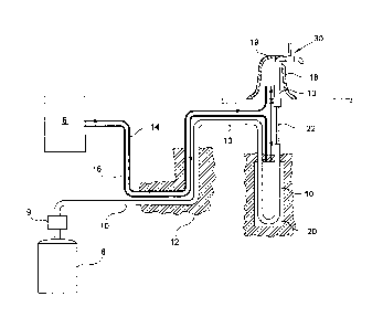
A system for providing an iced alcoholic beverage such as iced beer or
carbonated soft drink includes a source of
chilled coolant (16), and a beverage line (10) for supplying the beverage. A
heat exchanger (20) is disposed in the beverage line
(10) for cooling the beverage by heat transfer to the chilled coolant. A
restriction (22) or orifice forming a venturi is provided in the
beverage line (10) downstream from the heat exchanger. A chilled font (18) for
further cooling the beverage is provided downstream
from the orifice. The font (18) includes a dispenser tap (30) capable of
dispensing the beverage at a relatively low dispense rate and
at a relatively higher dispense rate. In use the beverage is first dispensed
at a relatively low dispense rate through a smaller orifice
of a narrow diameter at a preset low flow rate of beverage, and becomes ice or
slush (40). After a period of time the liquid beverage,
which may contain ice in the form of flakes, slush, crystals or the like is
dispensed at a faster rate, typically through a larger diameter
orifice.


French Abstract

L'invention porte sur un système pour distribuer une boisson alcoolisée glacée, telle qu'une bière glacée ou une boisson non alcoolisée gazeuse. Le système comporte une source de fluide de refroidissement froid (16) et une conduite de boisson (10) pour distribuer la boisson. Un échangeur de chaleur (20) est disposé dans la conduite de boisson (10) pour refroidir la boisson par le transfert de la chaleur au fluide de refroidissement froid. Un étranglement (22) ou un orifice formant un venturi est disposé dans la conduite de boisson (10) en aval de l'échangeur de chaleur. Une source froide (18) pour refroidir encore davantage la boisson est disposée en aval de l'orifice. La source (18) comprend un robinet de distribution (30) pouvant distribuer la boisson à un débit de distribution relativement faible et à un débit de distribution relativement plus élevé. Lors de l'utilisation, la boisson est tout d'abord distribuée à un débit de distribution relativement faible à travers un orifice plus petit d'un diamètre étroit à un débit de boisson faible prédéterminé, et devient de la glace ou de la glace fondante (40). Après une certaine période de temps, la boisson liquide, qui peut contenir de la glace sous la forme de flocons, de glace fondante, de cristaux ou autres, est distribuée à un débit plus rapide, typiquement à travers un orifice de plus grand diamètre.

Claims

Note: Claims are shown in the official language in which they were submitted.


7
CLAIMS:
1. A method for providing an iced beverage, comprising the steps in the
order of:
supplying the beverage to a heat exchanger;
cooling the beverage in the heat exchanger;
passing the beverage through a beverage line containing a Venturi tube or
constriction comprising an orifice of reduced diameter subsequently followed
by a pipe
of increased diameter relative to the orifice, thereby producing ice seeds in
the
beverage;
supplying the beverage and ice seeds to a font cooled to a temperature that is
cooler than the beverage,
dispensing the beverage and ice seeds through a dispensing tap.
2. The method as claimed in claim 1 wherein the beverage is an alcoholic
beverage
having an alcohol content by volume of from 2 to 10%.
1 The method as claimed in claim 1 or claim 2, wherein the dispensing tap
has a
single dispensing aperture which includes a partly closed dispensing position
and a
substantially fully open dispensing position, wherein restricted flow of
beverage
through the partly closed aperture due to ice acts as an indicator for an
operator to open
the tap to the substantially fully open dispensing position.
4. The method as claimed in any one of claims 1 to 3, wherein the beverage
is
supplied along the beverage line under pressure using compressed gas, and at a
temperature in the range of 2 to 6° C., to the heat exchanger, and the
beverage is cooled
in the heat exchanger to a sub-zero temperature of -2.5 to -4.8° C.
5. The method as claimed in claim 4, wherein the sub-zero temperature is
from
-2.5° C. to -4.3° C.

8
6. The method as claimed in any one of claims 1 to 5, wherein the
temperature of
the font, which is cooler than the beverage, is less than one to two degrees
cooler than
the beverage exiting the heat exchanger.
7. The method as claimed in any one of claims 1 to 6, wherein the ice is in
the form
of flakes, slush or crystals.
8. The method as claimed in any one of claims 1 to 7, wherein the beverage
is an
alcoholic beverage or a carbonated soft drink.
9. A method for providing an iced beverage, comprising the steps in the
order of:
supplying the beverage along a beverage line under pressure using compressed
gas and at a first temperature range to a heat exchanger;
cooling the beverage in the heat exchanger to a second temperature range;
passing the beverage through a Venturi tube or constriction comprising an
orifice of reduced diameter and subsequently followed by a pipe of increased
diameter
relative to the orifice, thereby producing ice seeds in the beverage;
supplying the beverage and ice seeds to a font, wherein the font is cooled to
a
temperature which is cooler than the beverage exiting the heat exchanger;
dispensing the beverage and ice seeds through a dispensing tap at a first flow
rate, the dispensing tap comprising an aperture, wherein ice particles build
up at the
aperture, restricting the flow of the beverage;
dispensing the beverage and ice particles through the dispensing tap at a
second
flow rate.
10. The method as claimed in claim 9 wherein the orifice has a diameter of
2.5 to
4 mm and wherein the diameter of the beverage line is about 8 to 10 mm.
11. The method as claimed in any one of claims 9 to 10, wherein the venturi
tube is
from 100 to 150 mm long.

9
12, The method as claimed in any one of claims 9 to 11, wherein the beverage
is
supplied under pressure of 28 to 36 psi using a mixture of compressed nitrogen
and
carbon dioxide.
13. The method as claimed in any one of claims 9 to 12, wherein the first
temperature
range is from 2 to 6° C.
14. The method as claimed in any one of claims 9 to 13, wherein the second
temperature range is from about -3.6° C. to -4.8° C.
15. A system for providing an iced alcoholic beverage or iced carbonated soft
drink,
comprising:-
a source of chilled coolant;
a beverage line for supplying the beverage;
a heat exchanger disposed in the beverage line for cooling the beverage by
heat transfer to the chilled coolant;
a restriction or orifice forming a venturi in the beverage line downstream
from
the heat exchanger;
a chilled or chillable font for further cooling the beverage downstream from
the
orifice; and
a dispenser tap , either adjacent the font or forming part of the font, for
dispensing the beverage.
16. A system as claimed in claim 15 wherein the orifice has a diameter of
2.5 to
4mm and the diameter of the beverage line is about 8 to 10mm.
17. A system as claimed in claim 15 or 16 wherein the length of the
restriction is
from 100 to 150mm long.
18. A system as claimed in any one of claims 15 to 17 wherein the dispenser
tap has
two valves one defining a relatively smaller dispense opening and one a
relatively.

10
larger dispense opening.
19. A system as claimed in any one of claims 15 to 17 wherein the dispenser
tap has
a single dispense opening which includes a partly closed dispense position and
a more
fully open dispense setting.
20. A system as claimed in claim 19 wherein the area of the dispenser tap
when the
valve is fully open is about 20 to 40 mm2 and when partly closed is from about
1 to
2mm2.

Description

Note: Descriptions are shown in the official language in which they were submitted.


CA 02711443 2014-10-08
1
System and Method for Dispensing Iced Beverages
Cross Reference to Related Applications
This application claims priority from Australian provisional patent
application
No. 2007903705, filed 9 July 2008 and also from Australian provisional patent
application No 2007906039 filed 2 November 2007.
Field of the Invention
This invention relates to a method or and system for dispensing iced
beverages,
particularly iced beer and similar alcoholic and/or carbonated ready to drink
beverages.
Background of the Invention
For many years, it has been common to chill beers, lagers and similar
beverages
in clubs, bars, hotels and other venues from room or cellar temperature,
typically
around 5 to 15 C to somewhere around 0 C for sale to patrons. In the following
specification, except where otherwise indicated, the term "beer" should be
construed as
including any, typically carbonated, and/or relatively low strength alcoholic
beverage
whether brewed or not. "Beverage" is to include carbonated soft drinks also,
Many beverage companies such as brewers, soft and ready to drink
manufacturers often require their beverages to be dispensed at a particular
temperature
or within a particular range of temperatures when sold in bars, hotels or the
like. For
example, in Australia, beers are typically required to be sold at a
temperature of
between 2 and 4 C inside the glass, which means that the beer has to be
dispensed from
the tap in a hotel or bar at around 1 to 2 C to allow for the heat capacity
of the glass,
which will typically be at a temperature greater than 4 C,
The beer, lager, or the like, is typically chilled by a heat exchanger. Such
heat
exchangers are usually either installed under a traditional bench or bar top
or in the keg
cellar, so the size of the heat exchanger is a consideration. At the same
time, the
dispensing apparatus must be sufficiently efficient to be able to dispense
beer at the
correct temperature, as prescribed by the beverage company, and on demand.
International Patent Application No PCT/AU2006/000459 entitled
"Improvements in control of heat exchangers"
discloses such a heat exchanger suitable for cooling
beverages.
WSLegn11047410\00058\10891168v1

CA 02711443 2014-10-08
2
The applicant's co-pending Australian provisional application No 2008900054
entitled "Improvements in Heat Exchangers for Dispensing Sub-Zero Beer" filed
4
January 2008; also
discloses a heat exchanger suitable for cooling beverages.
However, whereas until a few years ago, patrons of hotels and bars were happy
to drink chilled beer at a temperature of around 2 to 4 C, dispensing beer at
even cooler
temperatures, even subzero temperatures, is now fashionable in bars,
restaurants, hotels
and other venues. It will be appreciated that since beer contains alcohol, and
is
carbonated (under pressure) this depresses the freezing point of the beer such
that it
freezes at temperatures below the freezing point of water. Generally, the
stronger the
beer in alcohol content, the lower the temperature the beer freezes at.
Dispensing beers
at such low temperatures is tricky and is not possible without an increase in
the
performance of older type heat exchangers.
More recently, it has been mooted to produce iced beer, however this has not
proved practical with traditional draught beverage dispensing systems.
Any discussion of documents, acts, materials, devices, articles or the like
which
has been included in the present specification is solely for the purpose of
providing a
context for the present invention, It is not to be taken as an admission that
any or all of
these matters form part of the prior art base or were common general knowledge
in the
field relevant to the present invention as it existed before the priority date
of each claim
of this application.
Summary of the Invention
In a first broad aspect, the present invention provides a method providing an
iced beverage, typically alcoholic beverage such as iced beer, or the like,
comprising
the steps of:
dispensing chilled alcoholic beverage from a font or the like, the beverage
being
at a subzero temperature, typically in the range of minus 2,5 to minus 4.3 C;
cooling the font to a temperature which is cooler than the beer but not
substantially cooler, typically less than one to two degrees cooler than the
beverage;
wherein the beverage is first dispensed through a smaller orifice of a narrow
diameter at a preset low flow rate of beverage, which in turn becomes ice or
slush; and
=
after a period of time dispensing the liquid beverage, which may contain ice
in
the form of seeds, flakes, slush, crystals or the like through a larger
diameter orifice.
=
In a preferred embodiment the orifice is partially opened to produce the
preset
low flow then opened fully substantially immediately after the flow of
beverage
WSLega11047410 00058110891168v1

CA 02711443 2010-07-06
WO 2009/006691 PCT/AU2008/001008
3
through the reduced orifice becomes restricted under the low flow rate such
that no ice
or slush flow is therethrough, which restriction acts as an indicator for the
operator to
open the tap fully.
The opening of the tap to full flow also clears the ice or slush from the
small
orifice.
The heat exchanger is preferably, but need not be, a tubular heat exchanger of
the type described in PCT/AU2006/000459.
In a related aspect, the present invention provides a method providing an iced
alcoholic beverage such as iced beer or the like, comprising the steps of
supplying the beverage at a pressure of typically about 28 to 36 psi,
typically
using a mixture of compressed nitrogen and carbon dioxide, and a temperature,
typically in the range of 2 to 6 C, to a heat exchanger:
cooling the beverage in the heat exchanger to a temperature of about -3.6 C to
-
4.8 C;
passing the cooled beverage through an orifice (venturi tube) and subsequently
into a pipe of increased diameter relative to the orifice thereby creating a
venturi effect
in the beer line, causing the beverage to thereby release a, preferably
predetermined,
amount of carbon dioxide from the beverage and cause the production of ice
seeds in
the beverage;
dispensing the chilled beverage from a font or the like, cooled to a
temperature
which is cooler than the beer but not substantially cooler, typically less
than one to two
degrees cooler than the beverage;
wherein the beverage is first dispensed through a smaller orifice of a narrow
diameter at a preset low flow rate of beverage, which in turn becomes ice or
slush; and
after a period of time dispensing the liquid beverage, which may contain ice
in
the form of flakes, slush, crystals or the like through a larger diameter
orifice.
The desired temperature of the beverage on exit from the heat exchanger is set
dependant on the alcohol content of the beverage.
Typically the orifice has a diameter of 2.5 to 4mm compared with the diameter
of the rest of the beverage line of about 8 to 1 Omm. The venturi tube may be
around
100 to 150mm long.
In a related aspect the present invention provides a system for providing an
iced
alcoholic beverage such as iced beer or the like, comprising:-
a source of chilled coolant, such as a glycol set, or direct refrigeration
Freon
system;
a beverage line for supplying the alcoholic beverage;

CA 02711443 2010-07-06
WO 2009/006691 PCT/AU2008/001008
4
a heat exchanger disposed in the beverage line for cooling the alcoholic
beverage by heat transfer to the chilled coolant;
a restriction or orifice forming a venturi in the beer line downstream from
the
heat exchanger;
a chilled or chillable font for further cooling the beverage downstream from
the
orifice; and
a dispenser tap typically adjacent or part of the font, capable of dispensing
the
beverage at a relatively low dispense rate and at a relatively higher dispense
rate.
The dispenser tap may have two valves one defining a relatively smaller
dispense opening and one a relatively larger dispense opening or it may have a
single
dispense opening which includes a partly closed dispense position and a more
fully
open dispense setting.
Throughout this specification the word "comprise", or variations such as
"comprises" or "comprising", will be understood to imply the inclusion of a
stated
element, integer or step, or group of elements, integers or steps, but not the
exclusion of
any other element, integer or step, or group of elements, integers or steps.
Brief Description of the Drawings
A specific embodiment of the present invention will now be described by way of
example only, and with reference to the accompanying drawings in which:-
Figure 1 is a schematic view of system for dispensing iced beer;
Figure 2 is a schematic sketch of a beer tap in a partly open position;
Figure 3 is a schematic sketch of a beer tap in a fully open position; and
Figure 4 is a schematic front view of an alternative beer tap for use in the
system
and method of the present invention.
Detailed Description of Preferred Embodiments.
Referring to the drawings, Figure 1 shows schematically a view of the major
components of a system for dispensing iced beer embodying the present
invention.
Beer flows from a keg 8 or the like in a cellar at a temperature of from 2-6 C
along a
beverage line or pipe 10, typically having a diameter or 8 to 10111111. A CO2
driven
beverage pump, schematically shown at 9, is provided for maintaining a
positive back
pressure on the beverage line 10. The beverage is typically compressed using
both
compressed nitrogen and carbon dioxide gases. A typical tap pressure is 5 psi
and the
pressure range at the cellar may be from 25 to 40 psi, depending on the
beverage style.

CA 02711443 2010-07-06
WO 2009/006691 PCT/AU2008/001008
Typically, the beer is supplied from the cellar at a pressure of between 28
and 36psi
using the mixture of nitrogen and carbon dioxide gases.
.
The pipe is located in an insulated casing 12, only part of which is shown. It
is
to be noted that typically all cold or cool pipes or components of the system
will be
5 insulated, the insulation being omitted from the Figure for reasons of
clarity. Also
located in the casing are delivery 14 and return 16 pipes carrying chilled
coolant (such
as glycol) at a temperature of about -5 C from a cooler/heat exchanger (known
as a
"refrigeration set", shown schematically at 16 to a flooded font 18 and back
to the
refrigeration set for re-cooling the coolant.
The beer line 10 passes from the casing 12 to a heat exchanger 20 which may be
of the type described in PCT/AU2006/000459, but which could be any other
suitable
high efficiency compact heat exchanger. The beer exits the heat exchanger at a
temperature of -2 C to -3 C and immediately passes through a narrower orifice
section
22 having a diameter of from 2.5 to 4mm and a length of 100 to 150mm. At the
end of
the reduced diameter section 22 the beer line 10 increases in diameter to 8 to
10mm.
This creates a pressure drop at the end of the orifice 22. The pressure drop
acts as a
controlled method of stimulating production of ice seeds in the beer.
The sudden release of carbon dioxide at low beverage dispense rates results in
ice seeds being formed in the beer outlet line 10 and supports the production
of ice
crystals. The beer then passes into the flooded font 18 which defines a volume
19 filled
with glycol through which the beer line 10 passes. The beer is dispensed
through a two
stage beer tap 30 of the type described in Australian provisional application
No
2007903705.
Figures 2 and 3 show a schematic drawing of the two stage beer tap 30 of a
beer
font 18. The drawings are conceptual and illustrate the principals of
operation only
which can be implemented using other designs of tap.
The beer tap 30 is first only partially opened. How this is achieved is not
critical, and the type of valve closing the tap is also not critical. It is
also possible to
effect the method using an arrangement in which there are two valves, a main
pipe and
a bypass valve.
The diameter of the tap when the valve is fully open is about 6mm, giving an
area of about 30mm2. The tap may also be partially opened to produce a much
reduced
low flow rate through an aperture having an effective diameter of about 1.5mm
(but
which may be in the range of 1-2mm) , or an area of 1.75mm2.
In use, the tap is first only partially opened as shown in Figure 2 to produce
a
preset small flow through the reduced size aperture. This results in the
formation of ice

CA 02711443 2014-10-08
6
seeds in the pipe 10 within the heat exchanger, as described above due to the
pressure
drop as the beer exits the orifice 22, Ice slurry or frozen beer 40 is
discharged from the
tap 30 into a glass 42 or other receptacle under the tap, which continues to
flow for a
few seconds until the reduced diameter tap orifice becomes restricted with
ice, Behind
the restriction the beer itself does not freeze as the percentage alcohol
content in the
liquid phase goes up due to water in the form of ice precipitating out, both
as the
discharged slush and in the pipe downstream from the tap 10. The reduction of
the
flow acts as a trigger for the operator to open the tap fully, as shown in
Figure 2. At
this time the opening of the tap fully triggers the flow of sub zero beer
which may
contain ice crystals into the glass 40 to produce a semi-frozen beer drink,
Clearly this can be performed with other relatively weak alcoholic and/or
carbonated beverages such as lagers, ciders RTDs (mixtures of spirits and soft
drinks)
having a strength of a few % alcohol, say 2% to about 10%, however, the
temperature
of the iced drink will vary depending on the strength of the beverage, The
method may
also be used with non-alcoholic carbonated soft drinks having a high sugar or
dissolved
salts content, the dissolved sugar/salts depressing the freezing point of the
drink,
The dispensing of the iced beverage can be achieved by having set positions
using a single valve or by having a bypass valve and two flow paths one narrow
and
one much wider, A dispensing tap having narrow 50 and wider 52 flow paths is
shown
schematically in Figure 4.
Where reference is made herein to the diameter of a tube or orifice or the
like it
will be appreciated that the reference is to the effective diameter of the
tube or pipe and
that the orifice pipe or the like need not be circular in cross-section, but
may be any
suitable cross-section.
It will be appreciated by persons skilled in the art that numerous variations
and/or modifications may be made to the invention as shown in the specific
embodiments of the
invention as broadly
described. The present embodiments are, therefore, to be considered in all
respects as
illustrative and not restrictive.
WSLegah 047410 \ 00058 \10891 I 68v I

Representative Drawing
A single figure which represents the drawing illustrating the invention.
Administrative Status

2024-08-01:As part of the Next Generation Patents (NGP) transition, the Canadian Patents Database (CPD) now contains a more detailed Event History, which replicates the Event Log of our new back-office solution.

Please note that "Inactive:" events refers to events no longer in use in our new back-office solution.

For a clearer understanding of the status of the application/patent presented on this page, the site Disclaimer , as well as the definitions for Patent , Event History , Maintenance Fee  and Payment History  should be consulted.

Event History

Description Date
Time Limit for Reversal Expired 2020-08-31
Inactive: COVID 19 - Deadline extended 2020-08-19
Inactive: COVID 19 - Deadline extended 2020-08-06
Inactive: COVID 19 - Deadline extended 2020-07-16
Inactive: COVID 19 - Deadline extended 2020-07-02
Common Representative Appointed 2019-10-30
Letter Sent 2019-07-09
Inactive: Late MF processed 2018-01-08
Letter Sent 2017-07-10
Grant by Issuance 2016-08-30
Inactive: Cover page published 2016-08-29
Pre-grant 2016-06-09
Inactive: Final fee received 2016-06-09
Notice of Allowance is Issued 2015-12-10
Letter Sent 2015-12-10
Notice of Allowance is Issued 2015-12-10
Inactive: Approved for allowance (AFA) 2015-12-07
Inactive: Q2 passed 2015-12-07
Letter Sent 2015-10-22
Reinstatement Requirements Deemed Compliant for All Abandonment Reasons 2015-10-20
Amendment Received - Voluntary Amendment 2015-08-18
Deemed Abandoned - Failure to Respond to Maintenance Fee Notice 2015-07-09
Inactive: S.30(2) Rules - Examiner requisition 2015-02-19
Inactive: Report - QC passed 2015-02-11
Amendment Received - Voluntary Amendment 2014-10-08
Inactive: S.30(2) Rules - Examiner requisition 2014-04-08
Inactive: Report - No QC 2014-03-28
Letter Sent 2013-06-18
Request for Examination Received 2013-06-11
Request for Examination Requirements Determined Compliant 2013-06-11
All Requirements for Examination Determined Compliant 2013-06-11
Letter Sent 2012-09-14
Reinstatement Requirements Deemed Compliant for All Abandonment Reasons 2012-09-13
Deemed Abandoned - Failure to Respond to Maintenance Fee Notice 2012-07-09
Inactive: Cover page published 2010-10-01
Inactive: Notice - National entry - No RFE 2010-09-03
Application Received - PCT 2010-09-02
Inactive: IPC assigned 2010-09-02
Inactive: First IPC assigned 2010-09-02
Inactive: Declaration of entitlement - PCT 2010-08-05
National Entry Requirements Determined Compliant 2010-07-06
Application Published (Open to Public Inspection) 2009-01-15

Abandonment History

Abandonment Date Reason Reinstatement Date
2015-07-09
2012-07-09

Maintenance Fee

The last payment was received on 2016-07-07

Note : If the full payment has not been received on or before the date indicated, a further fee may be required which may be one of the following

  • the reinstatement fee;
  • the late payment fee; or
  • additional fee to reverse deemed expiry.

Patent fees are adjusted on the 1st of January every year. The amounts above are the current amounts if received by December 31 of the current year.
Please refer to the CIPO Patent Fees web page to see all current fee amounts.

Owners on Record

Note: Records showing the ownership history in alphabetical order.

Current Owners on Record
TEMPAK INTERNATIONAL PTY LTD
Past Owners on Record
BENJAMIN PAUL BAKER
Past Owners that do not appear in the "Owners on Record" listing will appear in other documentation within the application.
Documents

To view selected files, please enter reCAPTCHA code :


To view images, click a link in the Document Description column. To download the documents, select one or more checkboxes in the first column and then click the "Download Selected in PDF format (Zip Archive)" or the "Download Selected as Single PDF" button.

List of published and non-published patent-specific documents on the CPD .

If you have any difficulty accessing content, you can call the Client Service Centre at 1-866-997-1936 or send them an e-mail at CIPO Client Service Centre.


Document
Description 
Date
(yyyy-mm-dd) 
Number of pages   Size of Image (KB) 
Representative drawing 2016-07-24 1 9
Claims 2010-07-05 3 121
Description 2010-07-05 6 328
Drawings 2010-07-05 3 54
Abstract 2010-07-05 1 66
Representative drawing 2010-09-30 1 11
Claims 2014-10-07 4 121
Description 2014-10-07 6 326
Claims 2015-08-17 4 114
Notice of National Entry 2010-09-02 1 197
Courtesy - Abandonment Letter (Maintenance Fee) 2012-09-03 1 172
Notice of Reinstatement 2012-09-13 1 163
Reminder - Request for Examination 2013-03-11 1 118
Acknowledgement of Request for Examination 2013-06-17 1 177
Late Payment Acknowledgement 2018-01-07 1 165
Courtesy - Abandonment Letter (Maintenance Fee) 2015-09-02 1 171
Notice of Reinstatement 2015-10-21 1 163
Commissioner's Notice - Application Found Allowable 2015-12-09 1 161
Maintenance Fee Notice 2017-08-20 1 181
Maintenance Fee Notice 2019-08-19 1 180
PCT 2010-07-05 8 311
Correspondence 2010-08-04 2 62
PCT 2010-07-05 46 1,418
Amendment / response to report 2015-08-17 7 197
Final fee 2016-06-08 1 41
Maintenance fee payment 2018-01-07 1 27
Maintenance fee payment 2018-07-08 1 26