Language selection

Search

Patent 2712196 Summary

Third-party information liability

Some of the information on this Web page has been provided by external sources. The Government of Canada is not responsible for the accuracy, reliability or currency of the information supplied by external sources. Users wishing to rely upon this information should consult directly with the source of the information. Content provided by external sources is not subject to official languages, privacy and accessibility requirements.

Claims and Abstract availability

Any discrepancies in the text and image of the Claims and Abstract are due to differing posting times. Text of the Claims and Abstract are posted:

  • At the time the application is open to public inspection;
  • At the time of issue of the patent (grant).
(12) Patent: (11) CA 2712196
(54) English Title: SHOPPING CART HAVING A PUSHING HANDLE
(54) French Title: CHARIOT DE SUPERMARCHE A POIGNEE COULISSANTE
Status: Granted and Issued
Bibliographic Data
(51) International Patent Classification (IPC):
  • G07F 7/06 (2006.01)
(72) Inventors :
  • SONNENDORFER, HORST (Germany)
  • WIETH, FRANZ (Germany)
(73) Owners :
  • FRANZ WIETH
  • ANDREAS FILOSI
(71) Applicants :
  • FRANZ WIETH (Germany)
  • ANDREAS FILOSI (Germany)
(74) Agent: SMART & BIGGAR LP
(74) Associate agent:
(45) Issued: 2014-05-06
(86) PCT Filing Date: 2009-01-15
(87) Open to Public Inspection: 2009-07-23
Examination requested: 2011-01-06
Availability of licence: N/A
Dedicated to the Public: N/A
(25) Language of filing: English

Patent Cooperation Treaty (PCT): Yes
(86) PCT Filing Number: PCT/DE2009/000035
(87) International Publication Number: WO 2009089824
(85) National Entry: 2010-07-14

(30) Application Priority Data:
Application No. Country/Territory Date
20 2008 000 606.6 (Germany) 2008-01-15

Abstracts

English Abstract


The invention relates to a shopping cart having a sliding handle, which has
module-like functional elements, wherein
the functional elements are substantially accommodated in a recess of the
sliding handle and protrude so far out of the sliding handle
that good usability of the functional elements is given.


French Abstract

Chariot de supermarché à poignée coulissante, présentant des éléments fonctionnels modulaires. Les éléments fonctionnels sont logés essentiellement dans un évidement de la poignée coulissante, et sont en saillie par rapport à ladite poignée, de façon qu'une bonne maniabilité desdits éléments fonctionnels soit satisfaite.

Claims

Note: Claims are shown in the official language in which they were submitted.
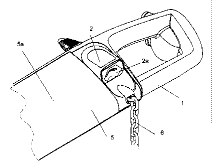

7
Claims:
1. A shopping cart having a pushing handle, into which functional elements
can be inserted
in a modular manner, the pushing handle having a receiving space for
functional elements, and
the functional elements being held in the receiving space such that they can
be removed again,
where there are grooves respectively tongues in the receiving space, into
which grooves
respectively tongues of a correspondingly complementary configuration of the
functional
elements can be pushed.
2. The shopping cart having a pushing handle as claimed in claim 1, wherein
the functional
element is a coin lock apparatus.
3. The shopping cart having a pushing handle as claimed in claim 1 or 2,
wherein the region
of the coin lock apparatus , in which the coin slot is situated, protrudes out
of the plane, in which
the inclined face is situated.
4. The shopping cart having a pushing handle as claimed in one of claims 1
to 3, wherein
there is a substantially horizontally running face below the coin slot.
5. The shopping cart having a pushing handle as claimed in claim 1, wherein
the grooves
respectively tongues which are present in the receiving space extend
substantially parallel to the
axis of the pushing handle.
6. The shopping cart having a pushing handle as claimed in claim 1, wherein
the functional
element is a holding device for a product scanner which can be operated by the
customer.

8
7. The shopping cart having a pushing handle as claimed in claim 1, wherein
the opening of
the receiving space which remains when the functional element is inserted can
be closed by a
cover, and the cover can be used as an advertising carrier.
8. The shopping cart having a pushing handle as claimed in claim 1, wherein
the pushing
handle has an inclined face, to which advertising can be attached, and the
functional element
which is inserted into the receiving space protrudes out of the plane, in
which the inclined face is
situated.
9. The shopping cart having a pushing handle as claimed in claim 1, further
comprising a
cover, wherein the opening of the receiving space which remains when the
functional element is
inserted can be closed by the cover.
10. The shopping cart having a pushing handle as claimed in any one of
claims 1 to 9, further
comprising snap-in lugs for fixing the functional elements in an end position
of the receiving
space.
11. The shopping cart having a pushing handle as claimed in any one of
claims 1 to 10,
further comprising an additional functional element inserted into the
receiving space.
12. The shopping cart having a pushing handle as claimed in claim 11,
wherein the functional
element and the additional functional element bear against opposite ends of
the receiving
element.

9
13. The shopping cart having a pushing handle as claimed in claim 2,
wherein the coin lock
apparatus includes a hand support which defines a recess.
14. The shopping cart having a pushing handle as claimed in claim 2,
wherein the pushing
handle has an inclined face, wherein a region of the coin lock apparatus, in
which a coin slot is
situated, protrudes out of a plane, in which the inclined face is situated.
15. A method of inserting functional elements into a pushing handle of a
shopping cart, the
method comprising:
providing the pushing handle into which the functional elements can be
inserted in a modular
manner, the pushing handle having a receiving space, where there are grooves
respectively
tongues in the receiving space, into which grooves respectively tongues of a
correspondingly
complementary configuration of the functional elements can be pushed;
inserting a functional element of the functional elements into the receiving
space and engaging
the respective tongues and grooves with one another; and
displacing the functional element in a direction along the tongues and grooves
until reaching an
end position in which the functional element bears directly against an edge of
the receiving
space.

Description

Note: Descriptions are shown in the official language in which they were submitted.


CA 02712196 2013-09-06
1 /9
Description
Shopping cart having a pushing handle
Technical Field
[0001] The invention relates to a shopping cart having a pushing handle which
has
functional elements which can be inserted in a modular manner.
Prior Art
[0002] EP 0537404 B1 has disclosed a pushing handle having functional
elements.
The pushing handle there has an advertising surface and a coin lock
apparatus as functional elements.
[0003] The substantially horizontal advertising surface is situated on its
upper side.
The coin slot of the coin lock apparatus is situated on the vertical front
side of
the pushing handle.
[0004] It is advantageous for the legibility of the advertising surface if it
is inclined
approximately in the direction of the user of the shopping cart. In the known
apparatus, an inclination of the advertising surface can be achieved by
inclining the entire pushing handle. As a result, however, the front side of
the
pushing handle would no longer be vertical, as a result of which the coin can
no longer be inserted as comfortably into the coin slot of the coin lock
apparatus.
Disclosure of the Invention
Technical Object
[0005] It is an object of the invention to provide a shopping cart having a
pushing
handle, the pushing handle having further functional elements in addition to

CA 02712196 2013-09-06
2/9
the functional element of the advertising surface, and it being possible to
operate said further functional elements easily and comfortably, even if the
functional element which acts as an advertising surface is inclined in the
direction of the user.
Technical Solution
[0006] The stated object is achieved by it being possible for the further
functional
elements to be inserted into a recess of the pushing handle, and by the
inserted functional elements protruding out of the inclined plane of the
pushing handle, in which plane the advertising surface lies.
Advantageous Effects
[0007] This advantageously brings about a situation where the further
functional
elements are accessible comfortably. In the case of the functional element
which acts as a coin lock apparatus, the coin slot is readily accessible
obliquely from above and part of the inclined plane which can serve as a hand
support during insertion of the coin still remains below the coin slot.
[0008] The further functional elements can be inserted in a modular manner
next to
the functional element which acts as an advertising surface. This
advantageously makes an individual flexible design of the pushing handle
possible. It is thus possible, for example, to insert another functional
element
into the pushing handle instead of the functional element which acts as a coin
lock apparatus. Another functional element of this type can be, for example, a

CA 02712196 2013-09-06
3/9
holding device for an electronic unit which is used by the user of the
shopping
= cart for what is known as "self-scanning", or a magnifying glass.
[0009] It is also possible, in addition to the functional element which serves
as an
advertising surface, to insert a plurality of additional functional elements
into
the pushing handle. For example, a functional element with a magnifying
glass and a functional element for a coin lock apparatus can be inserted into
the pushing handle.
Brief Description of the Drawings
[0010] Figure 1 shows a part of the pushing handle with an open recess, figure
2
shows the part of the pushing handle with the recess closed, and figure 3
shows the pushing handle with a part of the shopping cart.
[0011] Figure 1 shows a view of the interior of the pushing handle 1. The coin
lock
apparatus 2 is an independent modular functional element which is inserted
into the pushing handle 1.
[0012] There are grooves 4 in a receiving space 3 of the pushing handle 1,
which
grooves 4 correspond with appropriate tongues on the functional unit which
acts as a coin lock apparatus 2.
[0013] In the case of a finally assembled pushing handle 1, this receiving
space 3 is
closed by a cover 5 and cannot be seen by the user.
[0014] During the assembly of the coin lock apparatus 2, it is inserted into
the
receiving space 3, is introduced into the grooves 4 and is subsequently

CA 02712196 2013-09-06
4/9
displaced in the direction of the arrow P until it has reached an end
position.
In this end position, the coin lock apparatus 2 bears directly against the
edge
of the receiving space 3.
[0015] The coin lock apparatus 2 is designed in such a way that the result is
a
harmonic transition to the pushing handle. The region around the substantially
horizontal hand support is of recess-like design and the result is a flowing
transition to the cover 5 and the edge of the receiving space 3.
[0016] A chain 6 is fastened to the coin lock apparatus 2. A key (not shown in
this
view) which interacts in a known way with the lock of another coin lock
apparatus is situated at the end of the chain 6. This results in a finished
unit
which can be assembled quickly. No tool is advantageously necessary to
assemble the coin lock apparatus 2.
[0017] The coin lock apparatus 2 remains fixed by way of snap-in lugs (not
visible in
this view) which latch as soon as the coin lock apparatus 2 has reached its
end position. The grooves extend in the receiving space 3 parallel to the axis
of the pushing handle 1 and therefore also transversely with respect to the
usual direction, from which a force acts via the chain 6 on the coin lock
apparatus 2. The force which emanates from the chain 6 therefore
advantageously does not act on the snap-in lugs. In addition, the coin lock
apparatus 2 can also be fixed in this end position by way of a securing screw
or a securing pin.

CA 02712196 2013-09-06
5/9
[0018] Figure 2 shows the situation, in which the cover 5 closes the receiving
space
3.
[0019] At the same time, the cover 5 serves as an advertising surface 5a. The
advertising can be applied directly to the outside of the cover 5, or the
cover 5
is of transparent configuration and then the advertising can be applied to the
inside of the cover. In the case of a transparent cOver 5, there are guide
rails
on the inside, into which guide rails an advertising surface can be pushed.
[0020] Figure 3 shows the pushing handle 1 according to the invention in a
sectional
illustration, which pushing handle 1 is mounted in a known way on the handle
carrying arms 7 of a shopping cart.
[0021] In the mounted state, the pushing handle 1 is positioned slightly
obliquely, as
a result of which the advertising surface 5a can be seen in an improved
manner by the user of the shopping cart. The coin lock apparatus 2 extends
substantially horizontally. The result of this is that the region of the coin
lock
apparatus 2, in which region the coin slot 2a is situated, protrudes somewhat
out of the plane with the advertising surface.
[0022] A substantially horizontally extending surface 2b is situated below the
coin
slot 2a, which surface 2b can serve as a hand support for the user during the
insertion and removal of the coin and thus makes the insertion and removal
more comfortable.

CA 02712196 2013-09-06
6/9
[0023] The mounting of another modular functional element, for example a
magnifying glass or a holder for a scanner which can be operated by the user
of the shopping cart, takes place in the same way.
[0024] It is also possible to insert a plurality of modular functional
elements into the
receiving space 3. The modular functional elements can then bear against the
opposite edges of the receiving space 3 separately from one another, and the
cover 5 then closes the part of the receiving space 3 which remains between
them.
[0025] The individual functional elements are integrated into the overall
shape of the
pushing handle and protrude out of the plane, in which the surface 5a is
situated, to such an extent that satisfactory operating characteristics of the
functional elements are achieved.
Industrial Applicability
[0026] The invention is industrially applicable in every type of shopping cart
which is
made available to the customers against a deposit.

Representative Drawing
A single figure which represents the drawing illustrating the invention.
Administrative Status

2024-08-01:As part of the Next Generation Patents (NGP) transition, the Canadian Patents Database (CPD) now contains a more detailed Event History, which replicates the Event Log of our new back-office solution.

Please note that "Inactive:" events refers to events no longer in use in our new back-office solution.

For a clearer understanding of the status of the application/patent presented on this page, the site Disclaimer , as well as the definitions for Patent , Event History , Maintenance Fee  and Payment History  should be consulted.

Event History

Description Date
Maintenance Fee Payment Determined Compliant 2020-03-09
Inactive: Late MF processed 2020-03-09
Letter Sent 2020-01-15
Common Representative Appointed 2019-10-30
Change of Address or Method of Correspondence Request Received 2018-01-12
Small Entity Declaration Determined Compliant 2018-01-04
Inactive: Correspondence - Prosecution 2018-01-04
Small Entity Declaration Determined Compliant 2017-09-25
Small Entity Declaration Request Received 2017-09-25
Letter Sent 2017-08-29
Inactive: Multiple transfers 2017-08-09
Grant by Issuance 2014-05-06
Inactive: Cover page published 2014-05-05
Pre-grant 2014-02-12
Inactive: Final fee received 2014-02-12
Notice of Allowance is Issued 2014-01-07
Letter Sent 2014-01-07
Inactive: Approved for allowance (AFA) 2013-12-31
Inactive: Q2 passed 2013-12-31
Amendment Received - Voluntary Amendment 2013-09-06
Inactive: S.30(2) Rules - Examiner requisition 2013-03-08
Amendment Received - Voluntary Amendment 2011-08-31
Letter Sent 2011-01-19
Request for Examination Received 2011-01-06
Request for Examination Requirements Determined Compliant 2011-01-06
All Requirements for Examination Determined Compliant 2011-01-06
Inactive: Cover page published 2010-10-21
Inactive: Inventor deleted 2010-09-22
Inactive: Notice - National entry - No RFE 2010-09-22
Inactive: Inventor deleted 2010-09-22
Inactive: First IPC assigned 2010-09-10
Inactive: IPC assigned 2010-09-10
Application Received - PCT 2010-09-10
National Entry Requirements Determined Compliant 2010-07-14
Application Published (Open to Public Inspection) 2009-07-23

Abandonment History

There is no abandonment history.

Maintenance Fee

The last payment was received on 2013-12-20

Note : If the full payment has not been received on or before the date indicated, a further fee may be required which may be one of the following

  • the reinstatement fee;
  • the late payment fee; or
  • additional fee to reverse deemed expiry.

Please refer to the CIPO Patent Fees web page to see all current fee amounts.

Owners on Record

Note: Records showing the ownership history in alphabetical order.

Current Owners on Record
FRANZ WIETH
ANDREAS FILOSI
Past Owners on Record
HORST SONNENDORFER
Past Owners that do not appear in the "Owners on Record" listing will appear in other documentation within the application.
Documents

To view selected files, please enter reCAPTCHA code :


To view images, click a link in the Document Description column. To download the documents, select one or more checkboxes in the first column and then click the "Download Selected in PDF format (Zip Archive)" or the "Download Selected as Single PDF" button.

List of published and non-published patent-specific documents on the CPD .

If you have any difficulty accessing content, you can call the Client Service Centre at 1-866-997-1936 or send them an e-mail at CIPO Client Service Centre.


Document
Description 
Date
(yyyy-mm-dd) 
Number of pages   Size of Image (KB) 
Description 2013-09-06 6 188
Claims 2013-09-06 3 92
Description 2010-07-14 6 188
Claims 2010-07-14 2 52
Abstract 2010-07-14 2 76
Drawings 2010-07-14 2 45
Representative drawing 2010-09-23 1 11
Cover Page 2010-10-21 1 37
Representative drawing 2014-04-10 1 12
Cover Page 2014-04-10 1 38
Reminder of maintenance fee due 2010-09-22 1 113
Notice of National Entry 2010-09-22 1 195
Acknowledgement of Request for Examination 2011-01-19 1 176
Commissioner's Notice - Application Found Allowable 2014-01-07 1 162
Courtesy - Acknowledgement of Payment of Maintenance Fee and Late Fee (Patent) 2020-03-09 1 432
Commissioner's Notice - Maintenance Fee for a Patent Not Paid 2020-02-26 1 544
PCT 2010-07-14 22 608
Fees 2010-12-16 1 37
Correspondence 2014-02-12 1 48
Fees 2016-12-29 1 25
Prosecution correspondence 2018-01-04 26 779
Small entity declaration 2017-09-25 4 113