Note: Descriptions are shown in the official language in which they were submitted.
CA 02712307 2010-07-15
WO 2009/093005 PCT/GB2009/000111
GREETING CARD & GIFT PACKAGE COMBINATION
Description
The present invention relates to a gift package comprising a single sheet
formed of any
suitable material or combination of materials, including paper, paperboard,
cardboard,
corrugate, polymers, plastics, foils, or the like, including laminates of one
or more of
such materials and/or such materials or laminates thereof with or without a
coating or
thereon, cut to shape and folded to create a three dimensional box with a gift
card,
address label and necessary flaps to make a sealed unit, attached as part of
the package.
The package can be decorated using a laminated layer, for example a polymer or
foil
layer as the coating itself, on a paperboard or plastic or metal base, or a
base made of any
other type of material, for example using a. colored coating material on
cardboard, by
printing or screening a design or other decoration on a material, adhering a
decorative
material to a base material or any other material or method known or
hereinafter used to
create a decorative appearance on the package. The material for the package
may be
formed of a rigid or semi-rigid structure for the integrity of the package and
contents.
The package can be folded with face F showing for display purposes showing the
greeting card face by a retailer. This is covered by the packaging (I), when
folded and
sealed to be sent by post to the recipient.
The protective package does not require, but may have, a decorative
appearance, and can
include a space for the address of the recipient to be written and space for
postage. The
package can accept items placed in it loose, or in their own packaging.
The package includes a closure or more to seal the package once the gift has
been placed
inside. Additionally, the protective package preferably includes a self
sealing adhesive
strip or strips to seal the package or a tongue a groove method or a similar
method of
securely closing the package. The tongue and the closure flap may be removed
by being
cut or tearing along a perforated line so to enable the package to be stood up
and have a
1
CA 02712307 2010-07-15
WO 2009/093005 PCT/GB2009/000111
clean appearance of a regular greetings card. The address panel may or may not
be
decorated and may or may not be removable. If the address panel is not
removable, the
package may be folded in a way to make a three dimensional greetings card as
can be
seen in figure 3.
According to the present invention there is provided a packaging means
comprising a
content storage section, a panel section foldable against said storage section
along lines of
weakness, and means for sealing said content storage section, said panel
section being
configurable in at least two configurations in which said means for sealing
can seal said
content storage section such that the panel section is not free to move when
the content
storage section is so sealed.
In a preferable embodiment, the packaging means is such that, in all said
configurations,
the folded panel section lies substantially flat against the storage section
and no lines of
weakness cross the exposed part of the panel section.
In a preferable embodiment, the packaging means is such that, in all said
configurations,
part of said panel section is exposed whilst the rest of the panel section is
concealed, a
different part of said panel section being exposed in each configuration, and
said exposed
part of said panel section being exposed above the same face of the storage
section in all
such configurations.
The packaging means may be such that said sealing means comprises at least two
different sealing mechanisms. A first sealing mechanism of said at least two
different
sealing mechanisms may allow for repeated unsealing and resealing. A second
sealing
mechanism of said at least two different sealing mechanisms may only be sealed
and
unsealed once. Preferably, the first sealing mechanism can still be used after
the second
sealing mechanism has been used and unsealed.
The first sealing mechanism may comprises covering flaps for covering openings
in said
storage section, integrally attached to said panel section, and sealing flaps
integrally
2
CA 02712307 2010-07-15
WO 2009/093005 PCT/GB2009/000111
connected to said covering flaps, such that said sealing flaps fold inside the
storage
section to seal said content storage section and can be withdrawn to unseal
said content
storage section.
The second sealing mechanism may comprise adhesive, disposed on said sealing
flaps,
for sticking said sealing flaps to said storage section, such that said
covering flaps cover
and seal the openings in the storage section. The second sealing mechanism may
be
released by separating the part of the sealing flap containing the adhesive
from the part of
the sealing flap no containing the adhesive along a line of weakness.
Preferably, the sealing flaps and said cover flaps are separable along lines
of weakness
from said panel section.
Preferably, the two sealing means can be used in all the configurations.
The packaging means may be integrally formed from one piece of material.
Preferably,
the template from which the packaging means is formed can be perfectly
tessellated with
identical templates.
Preferably, the storage section is foldable, along lines of weakness, into a
rectangular
tube. Further, the packaging means may be folded to be substantially flat.
The attached drawings will help understand the invention. The drawings,
however do not
limit the invention in any way, and are presented to present the preferred
manufacture of
the invention:
FIG. 1 is a view of the invention, in its closed state as a gift package and
ready to mail.
The panel G is inserted into the box that has been created by folding panels
A, B, C, D
and E and attaching A to E by means of gluing or using an adhesive strip, or
by using a
tongue or other method to attach them together in order to create the box or
attached to
panel D by glue or adhesive strip or any other method. Panel H closes the top
of the box.
3
CA 02712307 2010-07-15
WO 2009/093005 PCT/GB2009/000111
Panels J & K act in the same manner as panels H & G and may be longer than
illustrated
in order to accommodate different methods of sealing the package.
FIG. 2 is a view of the invention with the panel I folded inside panel F so it
is facing
panel B. This is the configuration to be used for display purposes at the
point of sale, but
may also be the way the gift is chosen to be given to the recipient should the
gift not be
being mailed. The package is again closed, but no glue is used to seal the
package, so the
purchaser can open the package and write their greeting inside, on panel B.
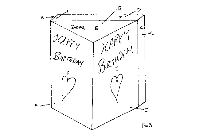
FIG. 3 is a view of the invention in an open configuration showing it being
displayed as a
three dimensional triangular card. The panels J & K and G & H have been
removed or
folded inside the package and the gift has been removed from the compartment
created
by folding panels A, B, C, D. Panel I may also be removed in order to leave a
more
standard greetings card.
FIG. 4 is a view of the invention in the process of being closed in order to
be mailed. The
gift giver has written their greeting on panel B and will now will insert
panels G & K into
the compartment created, or attach the panels G & K to the outside of panel D,
so that
panels H & J close over the void created by the folding of the invention.
FIG. 5 is a view of the invention in a basic, unassembled configuration. To
create the
package, Panel A is folded 90 degrees inwards to Panel B, Panel B is folded
inwards to
Panel C, Panel C is folded 90 degrees inwards to Panel D, Panel D is folded 90
degrees
inwards to Panel E and Panel A is attached to Panel E, forming a three
dimensional box
with no top or bottom. Panel F is then folded 90 degrees inwards to Panel B
and Panel I
can be folded either 90 degrees to the front face or the back face of Panel F
according to
whether the package is to be mailed or not. The bottom of the package is then
closed by
inserting Panel K into the open box shape created above, and Panel J acts as
the barrier to
create a container into which the gift may then be inserted. The Panel G can
then be
inserted into the top of the container as created above and Panel H then
closes the
package ready for giving or mailing.
4
CA 02712307 2010-07-15
WO 2009/093005 PCT/GB2009/000111
FIG. 6 is a bottom or top elevation view of the invention demonstrating the
way it can be
folded.
In order to understand the present invention, it is useful to first consider
Figure 5, which
shows a plan view of the unassembled template of an embodiment of the
invention.
The packaging unit is constructed by folding the template, which is formed
from a single
continuous piece of suitable material. The template consists of rectangular
panels (Panels
A-K) integrally connected along lines of weakness (represented by the solid
lines
separating the panels in Figure 5). The template is folded along these
predetermined
lines of weakness.
The dimensions of Panels B, D, F and I are substantially identical to each
other. The
dimensions of panels C and E are also substantially identical, as are the
dimensions of
Panels H and J.
In a contemplated embodiment, the combined width of panels G and H (that is
the
combined horizontal dimensions as shown in Figure 5) would be the same as that
of
panels J and K. Further, this combined width would be half the width (once
again, the
horizontal dimension as shown in Figure 5) of panel I. This would be
advantageous as it
would allow templates for the packaging unit to be perfectly tessellated on a
sheet of
material, which would minimize wastage of the material when cutting the
templates.
This tessellation would be achieved by positioning templates next to each
other, with
alternate templates rotated by 180 degrees, such that the template sections
defined by
Panels A-F lie next to each other.
As shown in Figure 6, the template is folded so that Panels A, B, C, D and E
form a
package or content storage section in the shape of a rectangular tube. Once
folded, Panel
A is stuck to panel E by any suitable adhesive means. This creates a loop
section, which
is foldable to create a rectangular tube. The rectangular tube thus formed in
bounded by
CA 02712307 2010-07-15
WO 2009/093005 PCT/GB2009/000111
Panels A and E on one side opposite Panel C on another, with the remaining
sides formed
by Panels B and D.
As also shown in Figure 6, the template can be further folded such that Panels
F and I lie
flat against panel B. As such, Panels F and I form a reversible cover for one
face of the
loop section. That is, either Panel F or Panel I can be folded to be visible
on the surface
of the loop section, as shown in Figures 1 and 2. It is also possible for the
loop section to
be folded flat, along the existing lines of weakness connecting the panels. As
such the
packaging unit can still be folded to be substantially flat, making it
convenient to transmit
the packaging unit at this level of assembly. The assembly of the template
into the
packaging as described above is very simple, which is also advantageous.
Figure 1 shows a perspective view of the packaging unit folded as shown in
Figure 6.
Panels F and I are folded such that Panel F lies flat against Panel B and
Panel I lies flat
against Panel F. As such, Panels B and F are hidden from view, and only one
side of
Panel I is exposed. Figure 2 shows an alternative configuration in which Panel
I has been
folded to lie between Panels B and F. That is, Panel I lies flat against Panel
B, whilst
Panel F lies flat again Panel I. In this configuration, Panels B and I are
completely
hidden from view, whilst only one side of Panel F is exposed. It is noted that
the sides of
Panels F and I exposed in the two alternative configurations are on different
sides of the
original template.
Figure 3 shows a further possible configuration of the packaging unit. In this
configuration, Panels F and I are folded such that they form a triangular
prism with Panel
B. In this configuration the packaging outwardly displays the face of Panel F
exposed in
the configuration of Figure 2, and the face of Panel I that is not exposed in
the
configuration of Figure 1. In an alternative to this configuration, Panel I
could be folded
between panels F and B, so that it lies next to panel F. In this configuration
the
packaging unit resembles a standard gift card, and stands up for display in
the same way
as such a card.
6
CA 02712307 2010-07-15
WO 2009/093005 PCT/GB2009/000111
The packaging unit of the present invention has the advantage that in all of
the
configurations shown in Figures 1, 2 and 3, no lines of weakness cross the
exposed
panels.
Figure 4 shows a perspective view of the packaging unit being folded into the
configuration of Figure 1. In the configuration of either Figure 1 or Figure
2, Panels H
and J fold to cover the open ends of the rectangular tube created by Panels A-
E. In order
to secure these panels in position (and thereby seal the rectangular tube in
which suitable
content can be stored) two sealing mechanisms are provided.
The first sealing mechanism allows the content storage section to be
repeatedly opened
and resealed. Preferably, the first sealing mechanism comprises folding Panels
H and J to
cover the ends of the rectangular tube storage section bounded by Panels A-E,
and
tucking Panels G and K inside the rectangular tube storage section. This
allows the ends
of the tube to sealed, but also allows for repeated opening and resealing by
pulling Panels
G and K back out of the storage section. However, alternative methods of
providing a
reusable seal could also be used, such as a reusable adhesive strip on Panels
G and K.
The reusable seal mechanism makes it easy to slide a gift or other contents
into or out of
the storage section, and to keep any contents in the storage section secure.
The second sealing mechanism provides a seal that can be used only once.
Preferably,
the second sealing mechanism comprises adhesive strips provided on Panels H
and J.
When panels G and K are folded to cover the rectangular storage section,
Panels H and J
are then also folded to lie next to, and to stick to, Panel D on the outside
of the
rectangular tube content storage section. When it is subsequently desired to
access the
content storage area, the seal is preferably broken by tearing away strips of
Panels H and
J which are disposed closer on Panels H and J to Panels G and K respectively
than the
adhesive strips. Preferably, these strips are predefined and prepared to ease
removal.
Once these strips are removed, portions of Panels H and J will remain attached
to Panel
D, but these portions will no longer be attached to the rest of Panels H and
J. That is to
say, the portion of Panels H and J that hold the adhesive strip are separable
along a line of
7
CA 02712307 2010-07-15
WO 2009/093005 PCT/GB2009/000111
weakness from the rest of Panels H and J. Therefore the remains of Panels H
and J
(which are not attached to Panel D), and Panels G and K will be free to move
and the
storage section will no longer be sealed.
The adhesive strips of the second sealing mechanism are disposed on the same
side of the
template as the face of Panel F that is exposed in the configuration of Figure
2. As such,
the second sealing mechanism can be used when with the packaging unit is
arranged in
the configuration of Figure 1 or Figure 2. That is, in the configurations of
both Figure 1
and 2, the same side of Panels H and J come into contact with Panel D of the
content
storage section. In other words, each sealing means can be used in both
configurations.
In a preferred embodiment, even after the seal of the second sealing mechanism
has been
broken, it is still possible for the first sealing mechanism to be used.
The different possible configurations of Figures 1 and 2 have the advantage
that the
packaging unit can be used to show different things on the same face of the
folded unit.
Therefore, Panel F may be used to present some decorative picture or message,
whilst
Panel I may be used to present other information. Further, Panel D is not
covered in
either of the configurations of Figures 1 and 2. Therefore, any decoration or
information
provided on the face of Panel D that is outwardly visible when the rectangular
storage
tube is formed will always be visible.
An example of how the alternative configurations and sealing mechanisms may be
used
is now discussed. The packaging unit may be displayed in the configuration
exposing a
face of Panel F. This face might display the front of a greetings card. A
message could
then be written on the reverse of Panel F, or on Panel B. Further, a message
could be
written on the face of Panel I not exposed in the configuration of Figure 1.
Optionally,
these panels may also carry further decoration.
The packaging unit could then be reconfigured to expose the face of Panel I.
This face
could provide space for printing an address and affixing postage, or Panel I
could contain
8
CA 02712307 2010-07-15
WO 2009/093005 PCT/GB2009/000111
an indication that postage has already been paid. In this configuration, the
Panel faces
mentioned above, carrying the decoration and any written message, are
concealed. The
package could then be transmitted in this configuration.
It is contemplated that the second, more secure, sealing mechanism would be
used during
any transmittal, for instance through the post. The first, reusable, sealing
mechanism
could be used whilst the packaging unit is on display in a shop and until the
packaging
unit is ready to be sent. As such, the adhesive strips of the second sealing
mechanism
would be covered with removable strips of a suitable non-stick material, so
that the
adhesive strips remain covered and do not stick to anything until they are
required.
When the packaging unit of the example is received after transmittal, the
recipient will be
able to break the seal of the second sealing mechanism and access whatever has
been
placed in the content storage section. Further they will be able to
reconfigure the
packaging unit so that the decorative face of Panel F is exposed and so that
they can view
any message or decoration on the other panels that were hidden in transit. As
such, the
packaging unit has the advantage that it gives the enjoyment of opening a
package or gift,
and also of opening a greetings card.
It is also contemplated that the packaging unit could subsequently be
displayed in the
manner of a greetings card. The packaging unit could be displayed in the
configuration
of Figure 3, as a three sided card, or Panel I could be folded in between
Panels F and B to
display the packaging unit in a configuration more like that of a standard
greetings card.
Either of these configurations would be facilitated by folding over Panels G
and K so that
they are hidden and do not interfere with standing the packaging upright.
Alternatively,
Panels G and K could be made detachable along the lines of weakness that
attach them to
Panels H and J. As such, when it was desired to display the packaging unit
after receipt,
Panels G and K could be easily removed.
It is also contemplated that Panel I could be made to be detachable along the
line of
weakness that attaches Panel Ito Panel F. After receipt, Panel I could then be
completely
9
CA 02712307 2010-07-15
WO 2009/093005 PCT/GB2009/000111
removed from the packaging unit so that the packaging unit could be displayed
in the
manner of a standard greetings card, without the extra panel folded inside.
Further advantageous embodiments of the invention are also contemplated. For
instance,
the dimensions of the packaging unit would preferably be chosen such that the
packaging
unit, when the content storage section if full, would easily fit through a
standard letter
box. It is also contemplated that the dimensions of the packaging unit would
be chosen
such that the packaging unit can be displayed in pre-existing shop display
stands, for
instance those used for displaying CDs.
It is also contemplated that other templates and shapes of packaging other
than the
rectangular shape of the example could also be used, whilst retaining the
ability to have
panels that can be configured to provide different exposed faces whilst
concealing other
faces of the panels. For instance, an alternative template might contain
further extra
panels between Panels F and I, to provide further possible configurations for
the
packaging unit.