Language selection

Search

Patent 2712464 Summary

Third-party information liability

Some of the information on this Web page has been provided by external sources. The Government of Canada is not responsible for the accuracy, reliability or currency of the information supplied by external sources. Users wishing to rely upon this information should consult directly with the source of the information. Content provided by external sources is not subject to official languages, privacy and accessibility requirements.

Claims and Abstract availability

Any discrepancies in the text and image of the Claims and Abstract are due to differing posting times. Text of the Claims and Abstract are posted:

  • At the time the application is open to public inspection;
  • At the time of issue of the patent (grant).
(12) Patent: (11) CA 2712464
(54) English Title: A COUPLING
(54) French Title: ACCOUPLEMENT
Status: Granted and Issued
Bibliographic Data
(51) International Patent Classification (IPC):
  • B24B 45/00 (2006.01)
  • F16D 41/06 (2006.01)
(72) Inventors :
  • HUNDEBOL, KELD OTTING (Denmark)
(73) Owners :
  • HH PATENT A/S
(71) Applicants :
  • HH PATENT A/S (Denmark)
(74) Agent: SMART & BIGGAR LP
(74) Associate agent:
(45) Issued: 2015-05-12
(86) PCT Filing Date: 2009-02-03
(87) Open to Public Inspection: 2009-08-20
Examination requested: 2013-07-30
Availability of licence: N/A
Dedicated to the Public: N/A
(25) Language of filing: English

Patent Cooperation Treaty (PCT): Yes
(86) PCT Filing Number: PCT/DK2009/000027
(87) International Publication Number: WO 2009100721
(85) National Entry: 2010-07-16

(30) Application Priority Data:
Application No. Country/Territory Date
PA 2008 00187 (Denmark) 2008-02-11

Abstracts

English Abstract


When, according to the invention, a coupling is provided between a driving
shaft (1) and a hub (6), said shaft (1)
being configured with several sets of grooves (2, 3) in which an elastic cord
(4) may extend, the cord (4) in the deep track (2) will
have a slight or poor engagement with the hub (6), while the cord in the low
track (3) will be pressed out into firm engagement
with the hub (6).


French Abstract

Selon l'invention, lorsqu'un accouplement est disposé entre un arbre d'entraînement (1) et un moyeu (6), ledit arbre (1) étant configuré avec plusieurs ensembles de rainures (2, 3) dans lesquelles peut s'étendre un cordon élastique (4), le cordon (4) dans la rainure profonde (2) aura un contact léger ou médiocre avec le moyeu (6), alors que le cordon dans la rainure peu profonde (3) sera pressé en contact ferme avec le moyeu (6).

Claims

Note: Claims are shown in the official language in which they were submitted.

8
Claims:
1. A coupling comprising a driving shaft or spindle which is capable of en-
gaging a surrounding driven hub, said shaft or spindle (1) being configured
with three or more longitudinal sets of grooves or tracks (2 and 3) shaped to
receive an extending cord (4), said grooves or tracks (2 and 3) having two
depths so that the extending cord (4) is receivable either in the deep track
(2) or in the low track (3), whereby there is no or slightly driving or firmly
driving contact, respectively, with the hub (6), characterized in that
the cord (4) is made of an elastic material.
2. A coupling according to claim 1, characterized in that the
grooves or tracks (2 and 3) each have curved bottoms, and that the cord (4)
has a correspondingly round cross-sectional shape.
3. A coupling according to claims 1 ¨ 2, characterized in that the
cord (4) extends in the tracks (2 and 3) from a bore or an opening (10)
through the shaft or spindle (1) at each end of the tracks (2 and 3).
4. A coupling according to claim 3, characterized in that the bore or
opening (10) extends in its respective end of the low track (3).
5. A coupling according to claims 3 - 4, characterized in that the
cord (4) is secured to the shaft or spindle (1) by means of a bead, a clamp-
ing ring (5) or a similar attachment device on the inner side of the opening
(10) in the shaft or spindle (1).

Description

Note: Descriptions are shown in the official language in which they were submitted.


CA 02712464 2010-07-16
1 EPb DG
2 8. 10. 2009
A COUPLING
0
The prior art
The invention relates to a coupling comprising a driving shaft or spindle
which is capable of engaging a surrounding driven hub, said shaft or
spindle being configured with three or more longitudinal sets of grooves or
tracks in which a cord may extend, said grooves or tracks having two
depths so that the cord may extend either in the deep track or in the low
track, whereby there is no or slightly driving or firmly driving contact,
respectively, with the hub,
Couplings of this type are known in many different embodiments, depend-
ing on operating conditions and on the purposes which the coupling, in
general, is to serve.
Where, e.g., a grinding tool is involved, it must be capable of centering the
tool precisely, just as the coupling must be easy to operate with a view to
replacement of the tool, either because it is worn, or where another tool is
needed.
Normally, such couplings are constructed as a spindle having threads, it
being possible to clamp the tool to the shaft by means of a flange and a
bolt.
However, this requires partly a tool, partly a very precise machining of the
surfaces or the fit between shaft and hub. The latter makes it expensive to
manufacture the coupling.
Where a one-way coupling is needed, a mechanical toothed arrangement
with pawls or the like will normally have to be incorporated. Such a me-

CA 02712464 2010-07-16
2
chanical device, too, is relatively expensive to manufacture, and it also re-
quires maintenance.
Another coupling type of the type defined in the invention is known from DE
1750227.
This coupling comprises a driving shaft which is capable of making no,
slightly driving or firmly driving contact, respectively, with a surrounding,
driven hub, and a plurality of loose bodies, which extend in grooves in the
exterior of the driving shaft, will be able to engage the driven shaft by
means of the centrifugal force.
This coupling is vitiated by certain defects and drawbacks, which are pri-
marily caused by the fact that the coupling is imprecise, as it may tend to be
engaged and/or disengaged non-uniformly, which will have as a result that
the centering is imprecise because of the uneven coupling engagement.
To this should be added the relatively large number of elements comprised
by the coupling, which adds to the manufacturing costs.
The object of the invention
It is the object of the invention to provide a coupling which is simple and
reliable in operation, precise in its coupling-together of the parts and their
positioning, and thereby centering of the engaging parts, noiseless and
moreover maintenance-free as well as easy to disassemble without the use
of tools.
This is achieved according to the invention by means of a coupling, wherein
the cord is made of an elastic material.

CA 02712464 2014-08-08
3
A coupling function is achieved in this manner, as the elastic cord in the
deep track involves no or only slightly driving contact with the surrounding
hub. Rotation of the shaft will cause the cord to be transferred from the
deep track to the low track, thereby applying an outwardly directed force to
the hub, so that the parts are coupled together firmly. This results in partly
a
uniform transfer of torque, partly an absolute centering of the parts, where,
normally, three sets of tracks are used.
It is ensured hereby that by the movement against the normal direction of
rotation in operation the cord will be released from the engagement and
thereby ensure that the driven hub and the tool may pulled off the shaft or
spindle easily and without difficulty. This takes place merely by stopping the
rotation and, by means of a slight backwards movement of the hub, will re-
lease this from the engagement with the driving shaft.
A one-way coupling is established hereby, which simultaneously ensures a
very precise centering of the parts, if the sets of the grooves extend equi-
distantly on the shaft. In some cases, this will mean that a larger diameter
requires more sets of tracks than three sets.
No noticeable wear of the parts will occur in operation, and, therefore, the
coupling will be just about maintenance-free.
When the bottoms of the grooves are configured to be curved and the cord
is configured with a circular cross-sectional shape, there will be an even
impact on the cord during its pressing-out and thereby engagement.
When the cords are mounted such that they are passed between bores or
openings through the shaft or spindle at the ends of the tracks, the cords
may be mounted and secured in a state in which there is a suitable

CA 02712464 2014-08-08
4
tightening because of the elasticity of the cords.
Finally, it is expedient to secure the cords by means of a bead, a clamp or
or a similar attachment device internally in the shaft or spindle at the ends
of the cords, for example, on the inner side of the opening in the shaft or
spindle.
The drawing
An example of an embodiment of the invention will be described more fully
below with reference to the drawing, in which
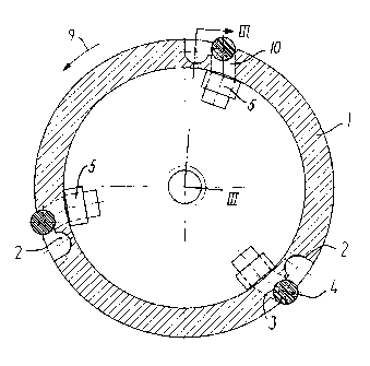
fig. 1 shows a sectional view of a shaft or spindle with three cords,
which are disposed in the deep tracks,
fig. 2 shows a sectional view where the cords extend in the low
tracks,
fig. 3 shows a longitudinal sectional view of the shaft or spindle,
seen in the direction in fig. 2,
fig. 4 shows a working tool during mounting and thereby in a disen-
gaged state, and
fig. 5 shows the tool coupled together with the shaft or spindle.
Description of an exemplary embodiment
The coupling according to the invention comprises a spindle or shaft 1,
which is shown in cross-section in figs. 1 and 2.

CA 02712464 2010-07-16
or shaft 1 by a tool 7.
It should be observed that the hub 6 is formed by a hollow body of rotation
without any requirements whatsoever with respect to the configuration, as
5 the bore merely has to have a diameter which is slightly larger than the
di-
ameter of the spindle or shaft 1.
Therefore, the coupling can work with an arbitrarily long hub, provided that
this is configured with an inner bore.
The description will therefore comprise the spindle or shaft 1, as shown in
figs. 1 ¨ 3.
In the following, the designation of the spindle or shaft will be spindle
alone,
which is connected with a rotating rotor (not shown) in a generally known
manner. In the example shown, the spindle 1 is configured as a length of
pipe. Three sets of grooves 2, 3 are arranged on the surface, offset 120
degrees. This ensures a completely precise alignment of the hub, as will be
explained later.
As shown in figs. 1 and 2, each set of grooves consists of two grooves 2
and 3, the one groove 2 being deeper than the other one 3.
The deep groove 2 is disposed in front of the lower groove 3 seen in the
direction of rotation 9.
These grooves extend longitudinally of the spindle 1, as shown in fig. 3.
The cross-sectional shape is as shown with round bottoms. The purpose of
these grooves 2, 3 is to provide a seat for a cord 4, which is preferably
made of flexible plastics, such as silicone or a similar material, corre-

CA 02712464 2010-07-16
6
sponding to what is used for the manufacture of 0-rings or the like.
The diameter of the cord 4 may e.g. be 8 mm, and the length is adapted to
the length of the spindle 1.
To secure the cord 4, a bore 10 is provided at both ends of the grooves 2,
3, so that the cord 4 may extend between the bores 10, as indicated in fig.
3.
The cord 4 is secured by means of clamping rings 5 or the like.
The function will now be explained with reference to figs. 4 and 5.
In fig. 4, the spindle 1 and the hub 6 have been joined, and the cord 4 is in
the front deep groove 2. With the cord 4 in this groove 2, there is no contact
between the parts 1 and 6, and the coupling is thereby in its disengaged
position.
Therefore, the hub 6 may be rotated freely in both its directions of rotation,
as indicated by arrows 8. Hereby, the hub with the tool 7 may freely be
pulled off and be applied to the spindle 1.
In the applied position, a rotation of the hub will cause movement of the
cords 4 from the deep track 2 to the low track 3, which means that the
cords 4 are pressed to engage the internal side of the hub 6, as shown in
fig. 5, and the coupling is thereby engaged.
The parts are thus coupled together, and the tool 7 may be driven precisely
in the direction of the arrow 8, since it is centered by the cords 4.
In case of change, the rotation is stopped, and the tool 7 with the hub 6

CA 02712464 2010-07-16
7
may be moved a small distance against the direction of rotation, whereby
the cords 4 will be moved back into the deep grooves 2, whereby the pres-
sure against the hub 6 ceases. Then, the hub may easily be replaced by
another one, following which the engagement may take place as described
above.
Where transfer of great torques or large dimensions are involved, more
than the described three sets of grooves 2 and 3 may be provided.

Representative Drawing
A single figure which represents the drawing illustrating the invention.
Administrative Status

2024-08-01:As part of the Next Generation Patents (NGP) transition, the Canadian Patents Database (CPD) now contains a more detailed Event History, which replicates the Event Log of our new back-office solution.

Please note that "Inactive:" events refers to events no longer in use in our new back-office solution.

For a clearer understanding of the status of the application/patent presented on this page, the site Disclaimer , as well as the definitions for Patent , Event History , Maintenance Fee  and Payment History  should be consulted.

Event History

Description Date
Common Representative Appointed 2019-10-30
Grant by Issuance 2015-05-12
Inactive: Cover page published 2015-05-11
Inactive: Final fee received 2015-02-18
Pre-grant 2015-02-18
Notice of Allowance is Issued 2014-12-22
Letter Sent 2014-12-22
Notice of Allowance is Issued 2014-12-22
Inactive: QS passed 2014-11-26
Inactive: Approved for allowance (AFA) 2014-11-26
Amendment Received - Voluntary Amendment 2014-08-08
Inactive: S.30(2) Rules - Examiner requisition 2014-07-16
Inactive: Report - No QC 2014-06-29
Letter Sent 2013-08-08
Request for Examination Received 2013-07-30
Request for Examination Requirements Determined Compliant 2013-07-30
All Requirements for Examination Determined Compliant 2013-07-30
Letter Sent 2010-11-12
Inactive: Cover page published 2010-10-20
Inactive: Single transfer 2010-10-18
Inactive: Reply to s.37 Rules - PCT 2010-10-18
IInactive: Courtesy letter - PCT 2010-09-15
Inactive: Notice - National entry - No RFE 2010-09-15
Inactive: First IPC assigned 2010-09-14
Inactive: IPC assigned 2010-09-14
Application Received - PCT 2010-09-14
National Entry Requirements Determined Compliant 2010-07-16
Application Published (Open to Public Inspection) 2009-08-20

Abandonment History

There is no abandonment history.

Maintenance Fee

The last payment was received on 2015-01-02

Note : If the full payment has not been received on or before the date indicated, a further fee may be required which may be one of the following

  • the reinstatement fee;
  • the late payment fee; or
  • additional fee to reverse deemed expiry.

Please refer to the CIPO Patent Fees web page to see all current fee amounts.

Owners on Record

Note: Records showing the ownership history in alphabetical order.

Current Owners on Record
HH PATENT A/S
Past Owners on Record
KELD OTTING HUNDEBOL
Past Owners that do not appear in the "Owners on Record" listing will appear in other documentation within the application.
Documents

To view selected files, please enter reCAPTCHA code :


To view images, click a link in the Document Description column. To download the documents, select one or more checkboxes in the first column and then click the "Download Selected in PDF format (Zip Archive)" or the "Download Selected as Single PDF" button.

List of published and non-published patent-specific documents on the CPD .

If you have any difficulty accessing content, you can call the Client Service Centre at 1-866-997-1936 or send them an e-mail at CIPO Client Service Centre.


Document
Description 
Date
(yyyy-mm-dd) 
Number of pages   Size of Image (KB) 
Representative drawing 2015-04-22 1 16
Cover Page 2015-04-22 1 42
Description 2010-07-16 7 240
Abstract 2010-07-16 2 66
Claims 2010-07-16 1 43
Drawings 2010-07-16 3 102
Representative drawing 2010-09-16 1 15
Cover Page 2010-10-20 1 41
Description 2014-08-08 7 226
Claims 2014-08-08 1 30
Maintenance fee payment 2024-01-26 46 1,882
Notice of National Entry 2010-09-15 1 197
Courtesy - Certificate of registration (related document(s)) 2010-11-12 1 127
Acknowledgement of Request for Examination 2013-08-08 1 176
Commissioner's Notice - Application Found Allowable 2014-12-22 1 162
PCT 2010-07-16 12 351
PCT 2010-07-19 5 245
Correspondence 2010-09-15 1 18
Correspondence 2010-10-18 3 65
Fees 2014-01-14 1 24
Correspondence 2015-02-18 1 43