Note: Descriptions are shown in the official language in which they were submitted.
CA 02712632 2010-07-22
WO 2009/092650 PCT/EP2009/050340
-1-
Inhaler
Description
The present invention relates to inhalers and, in particular, to inhalers for
the
delivery of dry powder medicament to the lung.
Oral or nasal delivery of a medicament using an inhalation device is a
particularly
attractive method of drug administration as these devices are relatively easy
for
patients to use discreetly and in public. As well as delivering medicament to
treat
90 local diseases of the airway and other respiratory problems, they have more
recently been used to deliver drugs to the bloodstream via the lungs, thereby
avoiding the need for hyodermic injections.
For a medicament in particulate form, the provision of an inhalable aerosol
requires an inhaler that can produce a repeatable dose of fine particles. In
order
for the particles of medicament to reach the deep lung area (alveoli) and thus
be
absorbed into the bloodstream, the particles must have an effective diameter
in
the range of approximately 1 to 3 microns. The portion of the emitted aerosol
which includes this range of particle size is known as the "fine particle
fraction"
(FPF). If the particles are larger than 5 microns, they may not be transported
by
the inhaled airflow deep into the lung, because they are likely to be trapped
in
the respiratory passages before reaching the deep lung. For example, particles
of
the order of 10 microns are unlikely to progress further than the trachea and
particles of the order of 50 microns tend to deposit on the back of the throat
when inhaled. Furthermore, if the particles are less than 1 micron in
effective
diameter, the particles may not be absorbed into the lung, because they are
small
enough to be expelled from the lung with the exhaled airflow.
The efficiency of a dry powder inhaler may be measured in terms of the fine
particle dose (FPD) or the FPF. The FPD is the total mass of active agent
which
is emitted from the device following actuation which is present in an
aerodynamic particle size smaller than a defined limit. This limit is
generally
CA 02712632 2010-07-22
WO 2009/092650 PCT/EP2009/050340
-2-
taken to be 5 microns although particles having a diameter less than 3 microns
are preferred, for the reasons stated above. The FPD is measured using an
impactor or impinger, such as a twin stage impinger (TSI), multi-stage
impinger
(MSI), Andersen Cascade Impactor (ACI) or a Next Generation Impactor (NGI).
Each impactor or impinger has a pre-determined aerodynamic particle size
collection cut points for each stage. The FPD value is obtained by
interpretation
of the stage-by-stage active agent recovery quantified by a validated
quantitative
wet chemical assay where either a simple stage cut is used to determine FPD or
a
more complex mathematical interpolation of the stage-by-stage deposition is
used.
The FPF is normally defined as the FPD divided by the emitted or delivered
dose which is the total mass of active agent that is emitted from the device
following actuation and does not include powder deposited inside or on the
surfaces of the device. The FPF may also, however, be defined as the FPD
divided by the metered dose which is the total mass of active agent present in
the
metered form presented by the inhaler device in question. For example, the
metered dose could be the mass of active agent present in a foil blister.
In conventional inhalers, the emitted dose (the amount of medicament that
enters the patient's airway) is around 80% to 90% of the dose ejected from the
inhaler. However, the FPF may only be around 50% of the emitted dose but the
variation in the respirable dose of known inhalers can be +/-20 to 30%. Such
variation is generally acceptable in the case of asthma drugs and the like.
However, it will be appreciated that for the pulmonary delivery of systemic
small
molecule and protein and peptide drugs or for the administration of drugs such
as insulin, growth hormone or morphine, this amount of variation in respirable
dose is unacceptable. This is not only because it is considerably more
important
to ensure that the patient receives the same intended dose of these types of
drugs
each time the inhaler is used, so that a predictable and consistent
therapeutic
effect is achieved, but a relatively low respirable dose represents a
significant
wastage of what may be an expensive drug.
CA 02712632 2010-07-22
WO 2009/092650 PCT/EP2009/050340
-3-
It will therefore be appreciated that for systemic pulmonary delivery, the
provision of an inhalable aerosol requires an inhaler that can deliver the
drug in a
highly efficient, accurate and repeatable manner leading to a more predictable
and consistent therapeutic effect which minimises any potentially harmful side
effects for the patient as well as reducing the amount of costly drug required
to
deliver a therapeutic dose.
To ensure that a powdered medicament is delivered with an accurately
controlled
90 range of particle sizes in order that they are absorbed effectively in the
lung, it is
necessary to deagglomerate the particles as they flow through the device prior
to
entry into the patient's airway.
It is known to separate particles of medicament by generating shear forces
between the particles, for example by providing a substantial velocity
gradient
across the particles. One way to achieve this is to provide the inhaler with a
cyclone chamber having an axial outlet and a tangential inlet. The drug is
entrained in an airflow and allowed to enter the cyclone chamber through the
tangential inlet. The high shear forces generated between the particles as
they
spin around the chamber in the airflow are sufficient to break-up agglomerates
of particles before they pass out of the chamber through the outlet. An
inhaler
having a cyclone chamber is known from the Applicant's own earlier patent
EP1191966 B1. A device for the pulverisation of particles or agglomerates of a
powdered inhalation medicament is also known from EP0477222 Al. The device
disclosed in this document comprises a rotationally symmetrical vortex chamber
with spaced inlet and outlet ports. The inlet ports direct drug laden air into
the
vortex chamber in a direction at a tangent or close to a tangent of the
chamber.
The present invention seeks to provide an inhaler which is capable of reliably
generating an inhalable aerosol of a powdered medicament with an effective
particle size that is sufficiently small for the medicament to be delivered to
and
absorbed into the lungs of a patient.
CA 02712632 2010-07-22
WO 2009/092650 PCT/EP2009/050340
-4-
According to the invention, there is provided an inhaler for producing an
inhalable aerosol of powdered medicament including an aerosolising device
having a chamber of substantially circular cross-section, inlet and outlet
ports at
opposite ends of the chamber for the flow of drug laden air through the
chamber
between said ports and, a bypass air inlet for the flow of clean air into the
chamber, said bypass air inlet being configured so that air entering the
chamber
through said inlet forms a cyclone in the chamber that interacts with the drug
laden air flowing between the inlet and outlet ports.
Preferably, the bypass air inlet is arranged so that air enters the chamber
through
said inlet substantially tangential to the wall of the chamber.
In a preferred embodiment, the chamber is configured so that the cyclone
interacts with the drug laden air flow so as to cause the drug laden air flow
to
assume a helical path as it flows from the inlet port to the outlet port.
Although it is known to provide an inhaler with a bypass air entry inlet, the
sole
purpose of that inlet or, more specifically, the bypass air which flows into
the
device through that inlet, is to reduce the overall pressure drop across the
device
and so make it easier for the patient to inhale. The bypass air inlets are
arranged
so that the bypass airflow is flowing in the same direction as the drug laden
air
when the two airflows meet so that there is limited interaction between the
bypass air and the drug laden air.
In one embodiment, the chamber is tapered. However, the walls of the chamber
may also be straight, i.e. parallel to the longitudinal axis of the chamber.
The chamber may be tapered in a direction extending from the outlet port
towards the inlet port. However, they may also taper in the opposite
direction.
CA 02712632 2010-07-22
WO 2009/092650 PCT/EP2009/050340
5-
The inhaler of the invention preferably includes a base and the inlet port is
formed in said base.
A mesh can be formed in the base and the inlet port can be formed from
openings in that mesh. The mesh can be formed in a separate component
attached to or inserted into an aperture in the base or, it can be formed
integrally
in the base.
The inlet port can be coaxial with a longitudinal axis of the chamber.
90 Alternatively, the inlet port may be offset from the longitudinal axis of
the
chamber.
Conveniently, the inlet port comprises at least one opening in said base.
The or each opening may extend at an angle relative to the longitudinal axis
of
the chamber. However, in a preferred embodiment, the longitudinal axis of each
opening is parallel to, or coaxial with, the longitudinal axis of the chamber.
Preferably, the chamber comprises an end wall opposite to the base at the
other
end of the chamber, the outlet port being formed in said end wall.
The end wall may comprise a mesh and the outlet port can be formed from the
openings in the mesh.
The mouthpiece may have a portion that extends beyond the end wall in a
direction away from the inlet port. That portion may taper outwardly away from
said end wall to form a diffuser.
In a preferred embodiment, the bypass air inlet is located at the base of the
chamber. Conveniently, the base forms a sidewall of the bypass air inlet.
CA 02712632 2010-07-22
WO 2009/092650 PCT/EP2009/050340
-6-
In another embodiment, the bypass air inlet is spaced from the base closer to
the
end wall. In one embodiment, the bypass air inlet is adjacent to the end wall
and
can be partially formed from the end wall.
The tangential bypass air inlet may be formed from an arcuately shaped flow
path.
In other embodiments, there can be more than one tangential bypass air inlet.
Preferably, there are at least two inlets on diametrically opposite sides of
the
90 chamber.
In a preferred embodiment, the chamber is formed within a mouthpiece.
However, in another embodiment, the outlet port of the chamber is connected
to a separate mouthpiece. If the chamber is formed within the mouthpiece, it
can
be a separate component within the mouthpiece. That component may be
separable from the mouthpiece.
Preferably, the inhaler comprises a blister piercing element operable to
puncture
the lid of a blister containing a dose of medicament to enable a user to
inhale
said dose through said chamber.
In one embodiment, the blister piercing member comprises a piercing element
upstanding from a surface and clean air inlet and drug laden air outlet flow
passages extending through the blister piercing member from said surface in
the
vicinity of each piercing element, said piercing element being operable to
puncture a clean air inlet opening and a drug laden air outlet opening in the
blister such that, when a user inhales, clean air can flow through the clean
air
inlet flow passage in the blister piercing member and clean air inlet opening
into
the blister to entrain the dose contained in the blister, the drug laden air
flowing
out of the blister through the drug laden air outlet opening in the blister
and
drug laden air outlet flow passage in the blister piercing member.
CA 02712632 2010-07-22
WO 2009/092650 PCT/EP2009/050340
-7-
Preferably, the drug laden air outflow passage is in communication with the
inlet
port of the chamber.
In one preferred embodiment, the clean air inlet opening comprises a plurality
of
peripheral clean air inlet openings that surround the drug laden air outlet
opening. Advantageously, the clean air inlet openings are arranged
symmetrically
around the drug laden air outlet opening.
In one embodiment, the inhaler further comprises a housing configured to
90 receive a strip having a plurality of blisters, each blister having a
puncturable lid
and containing a dose of medicament for inhalation by a user, means operable
to
drive the strip to sequentially move each blister into alignment with the
blister
piercing member and actuating means operable to cause the blister piercing
member to pierce the lid of said aligned blister.
In another embodiment, the inhaler comprises a housing configured to receive a
single blister having a puncturable lid and containing a dose of medicament
for
inhalation by a user and actuating means operable to cause the blister
piercing
member to pierce the lid of said blister received in the housing.
Embodiments of the invention will now be described, by way of example only,
with reference to the accompanying drawings, in which:-
FIGURE 1 is a simplified cross-sectional side view of a portion of an
inhalation
device according to an embodiment of the present invention;
FIGURE 2 is a cross-sectional view of the device shown in Figure 1 taken along
line X-X;
FIGURE 3 is a perspective view of the blister piercing head of the inhaler
shown
in Figure 1; and
FIGURE 4 is a perspective view of the cyclone chamber without the mouthpiece
of the inhalation device shown in Figure 1 or 2.
CA 02712632 2010-07-22
WO 2009/092650 PCT/EP2009/050340
8-
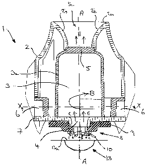
Referring now to the drawings, there is shown in Figure 1 a portion 1 of an
inhalation device according to an embodiment of the present invention having a
mouthpiece 2 defining a chamber 3 having a chamber wall 3a, a drug laden air
inlet port 4, an outlet port 5 and bypass air inlets 6. A cross-sectional view
taken
along the line X-X in Figure 1 is also shown in Figure 2.
The term "bypass" means that the air entering through these inlets 6 is clean
air,
i.e. air from outside the device 1 which does not have drug entrained in it.
90 The device includes a base 7 extending across a lower end of the mouthpiece
2
and closing the chamber 3. The drug laden air inlet port 4 is formed in, and
extends through, the base 7. In the illustrated embodiment, the drug laden air
inlet port 4 is coaxial with the longitudinal axis (A -A in Figure 1) of the
chamber 3, although it will be appreciated that the drug laden air inlet port
4 may
be offset or otherwise spaced from the longitudinal axis. The axis of the drug
laden air inlet port 4 may also be angled with respect to the longitudinal
axis of
the chamber 3, although in the preferred embodiment the axis of the drug laden
air inlet port 4 is parallel to the longitudinal axis of the chamber 3. It is
also
possible that the base 7 may have multiple drug laden air inlet ports 4
positioned
around the longitudinal axis of the chamber 3.
Although the base 7 could be formed integrally with the mouthpiece 2, it is
preferably formed as a separate component which is attached to the mouthpiece
2 during assembly. The mouthpiece 2 and base 7 may also be separable from
each other by a user to facilitate cleaning of the inside of the chamber 3.
As can be seen most clearly from Figures 2 and 4, which shows an underside
perspective view of the mouthpiece 2 without the base 7, the bypass air inlets
6
are channels formed in the sides of the mouthpiece 2 and the base 7 forms the
lowermost wall and encloses the lower end of the chamber (apart from the drug
laden air inlet port 4), but also forms the lower surface of the channels 6 so
that
the channels 6 are open only at each of their ends. In the illustrated
embodiment,
CA 02712632 2010-07-22
WO 2009/092650 PCT/EP2009/050340
-9-
there are two bypass air inlets 6 so as to direct clean air into the chamber
3.
However, there may only be one or several bypass air inlets 6. The bypass air
inlets 6 are preferably tangential to the chamber 3, although it will be
appreciated
that the desired air flow can also be obtained as a result of positioning the
bypass
air inlets 6 so that they are not at an exact tangent to the chamber 3 but are
offset from it.
In the illustrated embodiment, the bypass air inlets 6 are arcuate in shape,
although they may also be straight. They may also be circular in cross-section
90 and/or taper along their length in either direction.
As the bypass air inlets 6 are arranged tangentially or so as to direct the
bypass
air in a substantially tangential direction into the chamber 3, the clean air
flowing
through these inlets 6 into the chamber 3 spins around the chamber so as to
form a cyclone or vortex (as indicated by arrow "B" in Figure 1).
The outlet port 5 may be in the form of a mesh extending across the end of the
chamber 3 through which the entrained drug may flow out of the chamber 3 into
the patient's airway. Preferably, the mouthpiece 2 incorporates a flow
diffuser 5a
that extends beyond the outlet port 5 and has a cross-sectional area that
gradually increases towards the top edge 2a of the mouthpiece 2. The walls 2b
of
the diffuser 5a in this region may be curved in shape.
The chamber 3 may be straight, i.e. the inner curved surface 3a of the chamber
3
may extend parallel to the longitudinal axis of the chamber 3. However, in
other
embodiments, the chamber 3 may taper in either direction. In particular, it
may
widen as it extends from the drug laden air inlet 4 towards the outlet port 5.
The diameter and height of the chamber 3 have been shown to influence the
aerosolisation performance. Preferably the diameter of the chamber 3 is
between
15 mm and 25 mm and the height is 20 mm or more. However, to be able to
package a device into a convenient volume, smaller diameters and heights have
CA 02712632 2010-07-22
WO 2009/092650 PCT/EP2009/050340
- 10-
also been used to get a sufficient increase in performance with less demanding
therapies. In these cases diameters down to 9.5mm and heights down to 5.5mm
have been shown to give significant improvements in aerosolisation over a
device without cyclonic bypass air.
Air inlets 6 of dimensions 3.7 mm wide and 5.6 mm high have been shown to
work well although, surprisingly, the aerosolisation performance is less
sensitive
to the cross sectional area of the air inlets 6 which may then be
advantageously
varied to modify the resistance of the device to suit a particular therapy /
patient
90 group with little impact on performance.
A piercing device 8 is disposed beneath the mouthpiece 2 on the opposite side
of
the base 7 and may extend from or be connected to the base 7. As can most
clearly be seen from Figure 3, the piercing device 8 comprises a piercing head
9
having piercing elements 10 depending therefrom. The piercing head 9 has clean
air inlet flow passages 11spaced around a central drug laden air outlet
passage 12
(see Figure 3). In one embodiment, the inhaler 1 is configured to receive a
single
blister 13 containing a dose of medicament which is located beneath the
blister
piercing elements 10. The blister piercing elements 10 are configured to
puncture
the lid 13a of said blister 13 so that, when a patient inhales through the
mouthpiece 2, clean air enters the blister 13 through the air inlet flow
passages
11 (in the direction of arrow "C" in Figure 1) and entrains the dose contained
in
the blister 13. The drug laden air then flows out of the blister 13 through
the
central drug laden air outlet passage 12 (in the direction of arrow "D"). The
drug
laden air outlet passage 12 is connected to the drug laden air inlet port 4 of
the
chamber 3 so that it flows in an axial direction into the chamber 3 (in the
direction indicated by arrow "E"). At the same time, clean bypass air enters
the
chamber 3 through the tangential bypass air inlets 6 and spins around the
chamber 3 (in the direction of arrow "B") forming a vortex or cyclone.
It will be appreciated from Figure 3, that the air inlet flow passages 11 and
drug
outlet flow passage 12 are symmetrically arranged so the emitted drug dose has
CA 02712632 2010-07-22
WO 2009/092650 PCT/EP2009/050340
-11-
no dependence on the orientation of the inhaler around the chamber axis at the
time of inhalation. The blister piercing elements 10 extend over or bridge the
air
inlet flow passages 11 and drug outlet flow passage 12. The drug outlet flow
passage 12 may be larger than the total combined area of the air inlet flow
passages to increase flow area and to ensure that as much as possible of the
dose
is entrained in the airflow and removed from the blister 13.
Although reference is made to a unit dose device which receives only one
blister
13 at a time, the invention is equally applicable to a multi-dose dry powder
90 inhaler. For example, the device may have a housing configured to receive a
strip
having a plurality of blisters spaced along its length and means which are
operable to drive the strip to sequentially move each blister into alignment
with
the blister piercing member. Such a device may also be provided with an
actuator
to cause the blister piercing member to pierce the lid of an aligned blister.
A
device of this type is known, for example, from the Applicant's own earlier
application published as W005/037353 Al.
The cyclone interacts with the drug laden air flowing in a generally axial
direction
between the inlet and outlet ports 4,5 so as to cause the drug laden air flow
to
twist or follow a helical path towards the outlet port 5. The interaction of
the
vortex formed from the bypass air spinning around chamber 3 on the drug laden
air flowing into the chamber 3 in an axial direction has been found by the
Applicant to provide a marked improvement in performance of the inhaler.
Experimental results have shown that the drug laden air is accelerated as it
flows
through the chamber 3 and experiences increased shear forces and differential
velocites which further deagglomerates the particles and improves the fine
particle fraction of the emitted dose.
The graph below compares aerosolisation performance, for a typical drug and
fill
weight, of the cyclone bypass air invention and an otherwise similar device
where
the bypass airflow is flowing in the same direction as the drug laden air with
limited interaction between the bypass air and the drug laden air.
CA 02712632 2010-07-22
WO 2009/092650 PCT/EP2009/050340
-12-
Fine Particle Performance Comparison Between In-line & Cyclone Bypass Air
Devices
100%
_______________________________________________________________________________
_______________________________________________________________________________
_________________________________
90%
80%
70%
60%
40%
30%
20%
Zil
10%
0%
Fine Particle Fraction (FPF) Fine Particle Dose (FPD)
F J In-line Bypass Device El Cyclone Bypass Device
This graph illustrates approximately 200% increase in fine particle fraction
with
the cyclone bypass device
5
In the illustrated embodiment, the chamber 3 is provided within the mouthpiece
2. This has the advantage that the contact area between the device and drug
dose
is minimised as there is no additional airway to carry the deagglomerated drug
into the mouthpiece for delivery to the user and the device is compact.
However,
/0 it will be appreciated that the mouthpiece 2 could be separate to the
chamber 3
in which case a further flow path extends from the outlet 5 of the chamber 3
to
the inlet of the separate mouthpiece. The chamber 3 may also be a separate
component that is inserted within the mouthpiece 2 and could be detachable
therefrom. A separate chamber unit is shown in Figure 4, which locates within
15 the mouthpiece 2, as shown in Figures 1 and 2.
Many modifications and variations of the invention falling within the terms of
the following claims will be apparent to those skilled in the art and the
foregoing
description should be regarded as a description of the preferred embodiments
of
20 the invention only.