Note: Descriptions are shown in the official language in which they were submitted.
CA 02713383 2010-07-27
WO 2009/098009
PCT/EP2009/000656
APPARATUS AND METHOD FOR X-RAY FLUORESCENCE ANALYSIS OF
A MINERAL SAMPLE
Technical field
The present invention relates to an apparatus and method for X-ray
fluorescence analysis of a mineral sample.
Background of the invention
X-ray fluorescence (XRF) analysis is widely used for chemical analysis
of materials, and one of the applications is within geochemistry, e.g. for
prospecting and mining. During analysis in such applications, mineral
samples are irradiated by an X-ray beam, whereby fluorescent radiation is
emitted by elements contained therein. The fluorescent radiation can be
analyzed, for instance, by energy dispersive analysis, whereby the energies
of the photons are analyzed, and the intensity of each characteristic
radiation
frequency may be directly related to the amount of each element in the
mineral sample. Thus, the elements present in the mineral sample, as well as
the quantities of said elements, can be determined.
Traditionally in geochemistry applications, all material that were to be
analyzed, such as drill cores collected during prospecting, had to be sent to
a
laboratory for analysis. Today however, there are instruments available to
perform X-ray fluorescence analysis in situ, thereby providing a quicker
response. Examples of such portable, and often handheld, instruments are
commercially available from, for example, Niton.
For performing analysis in situ, there are typically two alternatives
available for sample preparation. According to the first alternative, the
instrument is simply directed towards the ground or against a plastic bag
holding the sample, i.e. the analysis is performed without any real sample
preparation. According to the second alternative, a sub-sample is picked out
and packed in a cup, which is inserted in the instrument and the analysis is
performed on the sample in the cup. To improve reliability of the analysis,
the
sample preparation here typically involves drying the sample at room
temperature or in a drying chamber, grinding the sample to achieve a fine-
grained structure, and then carefully packing the fine-grained sample into the
cup to ensure a uniform density. However, these known methods often only
CONFIRMATION COPY
CA 02713383 2015-03-25
28371-160
2
provides a measure related to the surface layer of the sample, and the
samples are normally required to be relatively thin, thereby providing a
measure on only a very limited amount of material.
Unfortunately, the level of uncertainty associated with the in situ
analysis is often considerable, and, even as the sample has been thoroughly
prepared, the in situ analysis often needs to be complemented with a
confirmatory laboratory analysis. This will normally reduce efficiency and
slow
down the field work. Further, known in situ methods are often tedious and
cumbersome to use. Thus, there is a need for in situ X-ray fluorescence
analysis that provides more reliable analysis and reduces the required sample
preparation. There is also a need for more cost-efficient ways of providing
reliable chemical material analyses on the field.
Summary of the invention
In view of the above, an object of the invention is to solve or at least
reduce the problems discussed above. In particular, an object is to achieve
improved reliability for in situ analysis, while reducing the required sample
preparation needed.
According to an aspect of the invention, there is provided an apparatus
for X-ray fluorescence analysis of a mineral sample comprising:
an X-ray source for generating an X-ray beam to irradiate the
mineral sample;
at least one fluorescence detector for measuring fluorescent
radiation emitted by the mineral sample when'irradiated by the X-ray beam;
a processing unit for providing an analysis of the mineral sample based
on the measurements made by the at least one fluorescence detector,
wherein said apparatus further comprises:
a sample container arranged to hold the mineral sample during the
irradiation, wherein the sample container is arranged to provide at least two
different irradiation paths through said mineral sample during irradiation.
An advantage with the arrangement is that it enables analysis of
elements having a wide range of atomic numbers in a single sample with
improved reliability and accuracy. This results in maximized detectability for
a
wide range of elements, while reducing the number of samples that needs to
be prepared. The present invention also leads to simplified sample
preparation, and to a faster and more cost-efficient analysis.
CA 02713383 2010-07-27
WO 2009/098009 PCT/EP2009/000656
3
As the accuracy and reliability of analysis performed in situ is
improved, the need for confirmatory laboratory analysis is reduced. This
means that informed decision can be made promptly and continuously as
prospecting proceeds, without waiting for laboratory results, and thus the
prospecting process can be accelerated and made more efficient.
Furthermore, a reduced need for laboratory analysis leads to enhanced cost
efficiency, not only as the in situ analysis typically is less expensive per
sample than laboratory analysis, but also as additional sample handling and
transportation associated with laboratory analysis is avoided.
The present invention is based on the understanding that, in order to
be detected, the fluorescent radiation needs to have sufficiently high energy
to escape the mineral sample without excessive attenuation. The fluorescent
radiation and absorption of elements having low atomic numbers differs
significantly from elements having high atomic numbers. By utilizing a sample
having two or more irradiation paths through the sample, and preferably
irradiation paths of various lengths through the material, each element of
interest can be analyzed using the irradiation path most appropriate. Hereby,
even fluorescent radiation of low energy can penetrate out from the sample
and be detected by the fluorescence detector. By means of the present
invention, an effective compromise between sensitivity and
accuracy/resolution can be achieved for essentially all materials. For
elements having low atomic numbers a relatively short path length may be
used (with low energy K-radiation), and for elements having high atomic
numbers (with high energy K-radiation) longer paths may be used. In this
latter case, the ability to accurately detect the elements is increased, since
the path may cross more atoms of the element. By an additional variation of
the excitation energy, an optimal choice of energy can be made, in particular
close to the K edge energy, for analysis of various elements.
The apparatus further preferably comprises controller means to adjust
an X-ray tube voltage of said X-ray source in accordance with the length of
the irradiation paths. This means that the energy of the X-ray beam is
adapted to the excitation energy of the elements which are most appropriate
to analyze for the current irradiation path, with improved reliability and
accuracy as a result.
The sample container may be rotatably arranged, enabling the
irradiation path through the mineral sample to be varied, which may enhance
the reliability and the accuracy of the analysis. Hereby, the requirement on
CA 02713383 2010-07-27
WO 2009/098009 PCT/EP2009/000656
4
e.g. uniformity and packing of the sample becomes lower, since a multitude of
irradiation paths in different directions can easily be obtained. Rotation of
the
sample may occur between measurements of different samples, or between
consecutive measurements on the same sample. However, preferably the
sample is being rotatable during said irradiation.
Furthermore, the sample container may have a uniform cross-section,
such as a circular cross-section, wherein the rotational symmetry allows the
mineral sample to be analyzed utilizing multiple irradiation paths having
essentially the same length, whereas the geometry between X-ray source, the
fluorescence detectors and the sample container may be kept constant. This
may also reduce variations in the results of the analysis due to the sample
compositions. However, alternatively the sample container may have a non-
uniform cross-section, such as, for example, an elliptical cross-section.
Hereby, rotation of the sample container allows the irradiation path through
the sample, and the length thereof, to be varied in a very simple way.
According to one embodiment, the sample container may have an
essentially tapered form. The tapering form of the sample container may e.g.
be in the form of a cone or a frustro-conical cone. Thus, the length of the
irradiation path may be varied by moving the X-ray beam, which may typically
be perpendicular to the tapering direction, in the tapering direction.
According to a preferred embodiment of the present invention, the
sample container is arranged to provide at least five different irradiation
paths
through the mineral sample during irradiation, said irradiation paths
preferably
being of different lengths through said mineral sample. Even more preferably
the apparatus may be arranged to scan the irradiation beam through a part of
the sample container, thereby provide a multitude of varying irradiation paths
through said mineral sample during irradiation. In this way a variety of
elements can be analyzed with an improved reliability and accuracy using a
single sample.
The length of the irradiation path through the mineral sample is
preferably in the range between 30 mm and 80 mm, and most preferably
relatively evenly distributed in said range so that it varies between
essentially
said end values. The chosen range depends inter alia on the atomic numbers
of the elements currently analyzed. The shorter irradiation paths of the
interval typically are used to study elements having atomic number 40 to 50,
whereas the longer irradiation paths of the interval typically are used to
study
elements having atomic numbers 51 to 80. However, these lengths are
CA 02713383 2015-03-25
28371-160
merely indicative and may vary, e.g. due to the sample conditions. As
understood by a person skilled in the art these intervals can further be split
up
into sub-ranges for increased accuracy. Also, irradiation paths having other
lengths may be utilized to study other atomic numbers.
5 Further, the X-ray tube voltage can be adapted to the excitation
energy
of the elements analyzed. The X-ray tube voltage may typically be varied
between 40 kVp and 160 kVp, where the lower voltages of the interval
typically are used for atomic numbers 40 to 50 and the higher voltages of the
interval typically are used for atomic numbers 51 to 80. It should be noted
that, these values are merely indicative and may vary due to the
measurement conditions. As understood by a person skilled in the art these
intervals can be further split up into sub-intervals for increased accuracy.
Also, voltages outside these intervals may be used.
According to an embodiment of the present invention, there may be
provided a transmission detector for measuring X-ray transmission through
the mineral sample during irradiation. Further, correction means to correct
the
measured fluorescent radiation due to variations in composition of the mineral
sample based on the measurements made by the transmission detector.
Thus, the analysis of the mineral sample may be compensated for variations
in the attenuation of the fluorescent radiation, which may arise, for example,
due to variations in composition of the mineral sample, such as density. This
results in improved reliability and accuracy of the X-ray fluorescence
analysis
and makes advanced sample preparation obsolete.
The apparatus also preferably comprises an energy spectrum analyzer
for separately measuring the Ka and Ko components of the fluorescent
radiation. Thus, the Ka and Ko components of the fluorescent radiation can be
separately compensated for variations in attenuation. As the attenuation
typically differs between Ka and Ko components this improves the reliability
and accuracy of the X-ray fluorescence analysis.
Such compensation is per se known from US 3,927,318.
This document disclose a fluorescent imaging system for selectively imaging
trace
amount of specific materials. The arrangement includes a compensation system
that
can be used to minimize the effect of the absorption of the fluorescent
radiation by
introducing a gain function. A more exact compensation for fluorescent
attenuation can be achieved through the separation of the various
components of the fluorescent radiation into Ka and Kp components. It also
CA 02713383 2010-07-27
WO 2009/098009 PCT/EP2009/000656
6
has an X-ray beam attenuation compensator. A more accurate correction for
the X-ray beam attenuation can be obtained by using the actual attenuation or
density values in the cross section. However, US 3,927,318 is related to a
totally different field, and also differs from the present invention inter
alia in
that it does not involve a sample container.
The at least one X-ray fluorescence detector and the transmission
detector may preferably be located apart from each other. This minimize the
overlap in the measured signals, and thereby improves the reliability and
accuracy of the apparatus. The transmission detector is preferably arranged
directly opposite to the X-ray source, whereas the fluorescence detector(s)
is/are hereby arranged in a direction up to, and preferably close to, 90
degrees angled to this primary radiation path. This also reduces the Compton
radiation. The differential cross-section for Compton radiation has a
radiation
minimum at 90 degrees. Consequently, such an arrangement reduces the
background radiation below the fluorescence peaks.
In a preferred embodiment of the invention, a first and a second X-ray
fluorescence detector may be arranged on opposite sides of the sample
container, and preferably at essentially right angles to the principal
direction
of the X-ray beam. Through this arrangement, the aggregated pulse response
from the first and second fluorescence detector is independent of where in the
sample the fluorescent radiation emanates. The arrangement of the
fluorescence detectors perpendicular to the principal direction of the X-ray
beam minimizes the effect of Compton scattering.
The apparatus is preferably portable, and easy to bring along for field
use. This typically means that the apparatus can be lifted by one or two
persons, and that it is small enough to be transported in an ordinary vehicle,
such as in a station wagon, a van, a pick-up truck, or an SUV. Further, the
apparatus may preferably be arranged with an outer housing or casing,
enabling a robust instrument which may endure the harsh environment that
may occur during field work. This may include considerable temperature
differences during use, outdoors or indoors, e.g. in an air condition van, or
during or transportation in a van, or on the back of a pick-up truck. The
instrument should also endure shocks that may arise under in these
circumstances. Furthermore, the casing/housing material preferably
comprises lead to prevent any radioactive radiation to escape and affect the
environment or any persons nearby.
CA 02713383 2015-03-25
28371-160
7
According to another aspect of the invention, there is provided a method
for X-ray fluorescence analysis of a mineral sample comprising the steps:
providing a mineral sample in a sample container;
irradiating said mineral sample with an X-ray beam;
measuring fluorescent radiation emitted by the mineral sample when
irradiated by the X-ray beam; and
providing an analysis of the mineral sample based on the measurements of
the fluorescent radiation;
wherein the sample container is arranged to provide at least two different
irradiation paths through said mineral sample during irradiation.
Hereby, similar advantages as discussed above in relation to the first
aspect of the invention are obtainable.
According to another aspect of the invention, there is provided an
apparatus for X-ray fluorescence analysis of a mineral sample comprising: an X-
ray
source for generating an X-ray beam to irradiate the mineral sample; at least
one
fluorescence detector for measuring fluorescent radiation emitted by the
mineral sample
when irradiated by the X-ray beam; a processing unit for providing an analysis
of the
mineral sample based on the measurements made by the at least one fluorescence
detector, wherein said apparatus further comprises: a sample container
arranged to hold
the mineral sample during the irradiation, wherein the sample container is
arranged to
provide at least two different irradiation paths through said mineral sample
during
irradiation; and controller means to adjust an X-ray tube voltage of said X-
ray source in
accordance with the length of the irradiation paths.
According to another aspect of the invention, there is provided a method
for X-ray fluorescence analysis of a mineral sample comprising the steps:
providing a
mineral sample in a sample container; irradiating said mineral sample with an
X-ray
beam; measuring fluorescent radiation emitted by the mineral sample when
irradiated by
the X-ray beam; and providing an analysis of the mineral sample based on the
measurements of the fluorescent radiation; wherein the sample container is
arranged to
CA 02713383 2015-03-25
28371-160
7a
provide at least two different irradiation paths through said mineral sample
during
irradiation, and wherein the method further comprises the step of adjusting an
X-ray tube
voltage of an X-ray source generating said X-ray beam in accordance with the
length of
the irradiation paths.
Other objectives, features and advantages Will appear from and be further
elucidated by the following detailed disclosure, from the attached dependent
claims as
well as from the drawings.
Brief description of the drawings
The above, as well as additional objects, features and advantages of the
present invention, will be better understood through the following
illustrative and non-
limiting detailed description of preferred embodiments of the present
invention, with
reference to the appended drawings, where the same reference numerals will be
used
for similar elements, wherein:
Figure 1 illustrates a schematic view of an apparatus for X-ray
fluorescence analysis of a mineral sample in accordance with an embodiment of
the
present invention;
Figure 2 illustrates a schematic view of a measurement set-up inside the
apparatus for X-ray fluorescence analysis of Fig 1;
Figure 3 illustrates a schematic view of a sample container to be used in
the apparatus of Fig 1; and
Figure 4a and 4b illustrates a block diagram of the apparatus for X-ray
fluorescence analysis of a mineral sample of Fig 1.
Detailed description of preferred embodiments
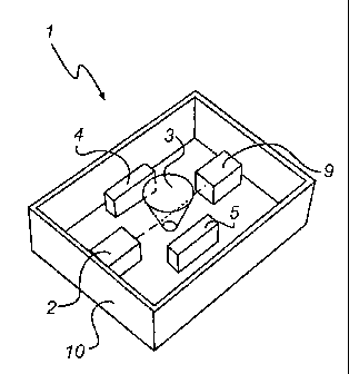
Referring to figure 1 to 4, a preferred embodiment of an apparatus 1 for X-
ray fluorescence analysis of a mineral sample will be described. The
CA 02713383 2010-07-27
WO 2009/098009 PCT/EP2009/000656
8
apparatus comprises an outer casing 10 which houses an X-ray source 2,
and two fluorescence detectors 4,5. Through an opening 8, preferably
closeable by means of a lid, a door or the like, a sample container 3 can be
inserted into the apparatus 1 in order to analyze a mineral sample contained
in the sample container 3. The apparatus is preferably connected to an
external display 7 in order to display the results of the X-ray fluorescence
analysis to a user, a printer for printing the results, and/or other suitable
user
interfaces. Further, the display 7 may alternatively be integrated in the
apparatus 1.
The X-ray source 2 may be a conventional X-ray tube equipped e.g.
with a Stiller collimator, comprising a stack of metal plates spaced a few
tenths off a millimeter apart, to form a collimated beam. The X-ray source 2
generates an X-ray beam having a principal direction parallel to the plane in
which the X-ray source 2 and the fluorescence detectors 4,5 are arranged.
The sample container 3 preferably has the form of a cone frustum and
is arranged in front of the X-ray source 2, preferably at a small distance to
avoid intensity loss of the X-ray beam. The longitudinal axis of the sample
container 3 is preferably perpendicular to the plane in which the X-ray source
and the fluorescence detectors 4,5 are arranged. Furthermore, the sample
container 3 is preferably rotatable about its longitudinal axis. It can also
preferably be translated along its longitudinal axis, thereby enabling the X-
ray
beam to irradiate portions of the sample container 3 having different
diameters.
Further, the X-ray source 2 is preferably provided with controller means
to automatically set the X-ray tube voltage based on the longitudinal position
of the sample container 3. Thus, the energy of the X-ray beam may vary with
the length of the irradiation path through the mineral sample.
The sample container 3 here has a height about 250 mm, and a
diameter varying from 30 mm at the bottom to 80 mm at the top. Moreover,
the sample container 3 is made of a material, such as plastic or glass, which
is transparent to the X-rays and fluorescent radiation used.
As depicted in figure 1, the two fluorescence detectors 4,5 are preferably
arranged on opposite sides of the sample container 3. Both fluorescence
detector 4,5 face the sample container and are arranged at an essentially
right angle to the principal direction of the X-ray beam. The fluorescence
detectors 4,5 can be conventional solid-state detectors preferably with a high
degree of energy dispersion. Each fluorescence detector 4,5 is connected to
CA 02713383 2010-07-27
WO 2009/098009 PCT/EP2009/000656
9
the processing unit. The processing unit may be a conventional CPU, on
which runs software in order process input data to obtain the resulting X-ray
fluorescence analysis. A multichannel analyzer (MCA) can also be provided
between the fluorescence detectors 4,5 and the processing unit.
When a mineral sample is to be analyzed it is filled into the sample container
3, which is then sealed and inserted into the apparatus 1. Beginning the
analysis, the sample container 3 may e.g. be located in its lower longitudinal
end position, and the X-ray tube voltage is set to 160 kVp. Thus, the X-ray
source 2 generates an X-ray beam, which irradiates the upper portion of the
sample container 3 having a diameter of 80 mm. The sample container 3 is
then gradually translated along its longitudinal direction so that various
portions of the sample container 3 are irradiated, thus changing the length of
the irradiation path through the mineral sample. During translation, the X-ray
tube voltage is changed accordingly in order to adapt the energy of the X-ray
beam to the excitation energy for the element currently analyzed. At the end
of the analysis, the X-ray beam is directed at the lower portion of the sample
container 3 having a diameter of 30 mm and the X-ray tube voltage is now 40
kVp. The translation can be continuous, but it could equally well be performed
by positioning the sample container 3 in a series of positions along the
longitudinal axis, such as two, three or more positions, and for each position
irradiate the sample container 3. For example, two positions could be utilized
by first irradiating the sample container 3 in its lower longitudinal end
position,
then shifting the sample container 3 to its upper longitudinal end position
where it is also irradiatied.
Throughout the irradiation, the sample container 3 is preferably rotated
around its longitudinal axis in order to improve the accuracy of the X-ray
fluorescence analysis. The rotational speed is typically 5 to 20 rpm.
As the mineral sample is irradiated, fluorescent radiation is emitted by
the elements contained therein. The fluorescent radiation is measured by the
fluorescent detectors 4, 5, each producing a signal containing a continuous
distribution of pulses, the voltages of which are proportional to the incoming
photon energies. This signal can be processed by the multichannel analyzer
and/or the processing unit to obtain a spectrum representing the elements
contained in the mineral sample. If the apparatus 1 has been properly
calibrated against known levels of the respective element the amount of each
element can be quantified. The result can be displayed to the user on the
display 7.
CA 02713383 2010-07-27
WO 2009/098009 PCT/EP2009/000656
As illustrated in figure 1, the apparatus 1 may further comprise a
transmission detector 9, wherein the X-ray source 2 and the transmission
detector 9 are arranged on opposite sides of the sample container 3. The
transmission detector 9 may preferably be located along the principal
5 direction of the X-ray beam in such a way that it faces the X-ray source
2, to
best measure transmission of X-rays through the irradiation path of the
sample container. Furthermore, the transmission detector 9 can be a
conventional solid-state detector preferably with high sensitivity. During
analysis the transmission detector 9 measures the X-rays passing through the
10 mineral sample, and e.g. produces a signal containing a continuous
distribution of pulses, the voltages of which are proportional to the incoming
X-rays. The output signal of the transmission detector is fed to correction
means, where the X-ray fluorescence analysis can be adjusted for variations
in compositions of the mineral sample as will be explained below.
The pulse number measured by the transmission detector 9 relates to
the attenuation of the X-ray beam as described by equation 1:
N = No = exp(¨,u = d) (Eq. 1)
where
N is the pulse number measured by the transmission detector;
No is the pulse number that would be detected with no attentuation
present;
IA is the linear attenuation coefficient cm -1; and
d is the diameter of the sample.
The diameter d of the sample container, and the pulse numbers N and
No are all known. Thus, the attenuation coefficient for the mineral sample can
be computed using equation 2:
N
ln(---1)
N
14= (Eq. 2)
d
The measured pulse number for the fluorescent radiation is adjusted
for variations in composition of the mineral sample according to equation 3:
CA 02713383 2010-07-27
WO 2009/098009
PCT/EP2009/000656
11
N corr = N Ocorr = exp(,u = d) (Eq. 3)
where
Ncorr is the corrected pulse number; and
Nocorr is the pulse number measured by the fluorescence detectors.
The correction is related to the attenuation of the fluorescent radiation,
and provides an improved accuracy when determining the amounts of the
various elements/materials. The intensity of the primary radiation can be
established by means of calibration tests, which may be repeated regularly,
such as once a day, or each time the apparatus is restarted.
A more accurate compensation for fluorescent attenuation can be
achieved by separating the various components of the fluorescent radiation
utilizing an energy spectrum analyzer for separately measuring the Ka and Ko
components of the fluorescent X-rays. Even in this case, with a separation of
the K radiation in alfa and beta components, a correction for different
attenuation of the radiation can be made, as discussed above. To this end, an
effectiv can be determined from the attenuation measurements, and can
subsequently be corrected for the actual energy of the K radiation. The
energies for Ka and Ki3 components of the fluorescent X-rays are fixed, and
previously known for various elements and materials.
The present invention has now been disclosed with reference to certain
embodiments. However, as would be readily acknowledged by a person
skilled in the art, other embodiments than the ones disclosed above are
equally possible. For example, the number of fluorescence detectors may
vary, and be fewer or more than two, and the number of transmission
detectors may also vary. Also the fluorescence detectors do not have to be
arranged in the same plane as the sample container. Still further, the sample
may be rotated and translated in various fashions during the irradiation, and
many different irradiation paths may be provided. In an alternative
embodiment the X-ray source may also be translated and/or rotated while the
sample container is held still, thereby providing the same relative motion as
when the sample container is moved. Further, the sample container may take
many different shapes and dimensions. Such and other modifications of the
above-discussed embodiments must be considered to be encompassed by
the invention as defined by the appended claims.