Note: Descriptions are shown in the official language in which they were submitted.
CA 02713435 2010-07-28
WO 2009/097546 PCT/US2009/032673
TWIN PACKAGING LINE AND METERING SYSTEM
FIELD OF THE INVENTION
The invention relates to packaging of primary articles, such as cans or
bottles, in multiple
packaged cartons. More particularly, but not exclusively, the invention
relates to an apparatus
and method of packaging articles conveyed in more than one adjacent streams
simultaneously;
an apparatus for and method of metering and grouping articles conveyed in two
lines in more
than one adjacent streams; a packaging line incorporating such a metering
system and
including an integrated tertiary packaging system and quaternary wrapping
system.
BACKGROUND OF THE INVENTION
In the field of packaging it is required to provide adaptable machines that
are capable of
packaging a variety of types of primary article, such as cans and bottles,
into secondary
packages (cartons) that contain or hold together an array of articles in a
multipack. It is known
to provide such multipacks to subsequent sub-assemblies for collating a number
of multipacks
or cartons into a tertiary package. Furthermore it is known to provide groups
of such tertiary
packages to yet a further subsequent sub-assembly for collating a number of
such tertiary
packages and wrapping them into palletised load for distribution to retail
outlets.
In the interests of economic and efficient packaging, it is required to
achieve the highest
throughput of cartons and wrapped tertiary packages as possible. The linear
size of a packaging
line; the types of article; and the type of carton that can be accommodated by
a packaging line
are also important considerations as well as the wear on the machine. Higher
throughputs can
be achieved if machine lines can be run faster; however this is not always
possible when
manipulation of cartons introduces complexities that limit the run-speed.
Additionally, running
at high-speeds can cause components of a machine to suffer wear and damage due
to friction
and heat. This in turn can cause down time to the packaging machine and
potentially the entire
bottling line as well as costly repair to the machines. It is therefore
advantageous to optimise
machine output in other ways than simply increasing the machine run-speed. In
fact because of
-1-
SUBSTITUTE SHEET (RULE 26)
CA 02713435 2010-07-28
WO 2009/097546 PCT/US2009/032673
the wear, friction and heat damage that can be caused, it is desirable to run
machines at slower
speeds without compromising the throughput of packaged articles.
Many known machines are capable only of packaging one type of carton and
bottling plants can
be required to use a plurality of machines to package different carton types;
each machine
takes up considerable floor space and can be expensive to purchase and
operate. It is therefore
desirable to have packaging machines that are adaptable for accommodating a
variety of
articles; carton types and carton sizes. It is also desirable to minimise the
linear size of
packaging machines to reduce the amount of floor space occupied.
The present invention seeks to provide a number of advantages or improvements
in the field of
packaging.
SUMMARY OF INVENTION
According to a first aspect, the invention provides a packaging machine
comprising at least two
independent paths upon which primary articles to be contained by a secondary
carton are
conveyed from an infeed end of the packaging machine to an integral tertiary
packaging device
wherein secondary cartons directly output from said two independent paths are
merged and
combined with a tertiary package characterised in that tertiary packages are
conveyed along a
transfer means out of said tertiary packaging device travelling at a speed the
same as that of
each of the paths upon which incoming primary articles are disposed.
Preferably the packaging machine comprises a device for grouping articles
operable to interact
with articles on each path simultaneously. Optionally, the device for grouping
articles disposed
between two adjacent ones of said paths, for grouping and metering primary
articles conveyed
on each of the two paths simultaneously.
Additionally, or alternatively, the packaging machine comprises a transfer
conveyor for
supplying a tertiary article to the tertiary packaging device for combination
with the processed
articles being merged, the transfer conveyor having an infeed end disposed
above or below a
-2-
SUBSTITUTE SHEET (RULE 26)
CA 02713435 2010-07-28
WO 2009/097546 PCT/US2009/032673
horizontal plane containing said two paths and being inclined such that an
output end of the
transfer conveyor is disposed between and in substantially co-planar alignment
with said two
paths whereat the processed articles are merged and combined with the tertiary
article.
Optionally, a finishing device is disposed upstream of said tertiary packaging
device, the
finishing device being structured and arranged to receive articles directly
output from the
tertiary packaging device, and to convey finished packages out of said
finishing device along a
transfer means travelling at the same speed as each of the paths upon which
incoming primary
articles are disposed.
Optionally the packaging machine comprises means for supply of secondary
packages to each
of the two paths for combination with the primary articles; a means for supply
of tertiary
packages for combination with the primary articles and secondary packages, the
means of
supply of the tertiary package being up stream of the means for supply of the
secondary article;
and a single loading device operable to load, in turn, secondary packages and
tertiary packages
to the respective means for supplying secondary and tertiary articles.
Accordingly, a second aspect of the invention provides, a device for grouping
articles to be
contained by a secondary carton, the device comprising a first series of
spacer elements
arranged to move along a pre-determined path, each spacer element operable to
engage at
least one article from a first infeed stream and to convey articles through a
working reach of
the device, the device further comprising a second series of spacer elements
arranged to move
along a similar pre-determined path, each spacer element of the second series
operable to
engage at least one article from a second infeed stream of articles,
characterised in that a
spacer element of the first series of spacer elements is coupled to a spacer
element of the
second series of spacer elements by a drive means such that the coupled spacer
elements are
conveyed at the same speed.
Preferably, the spacer elements of the first and second series are disposed
back-to-back and
operate on separate streams of primary articles disposed on separate
independent conveyors
to synchronise the processing of primary articles on said separate independent
conveyors such
that primary articles processed by the device as they are conveyed on each of
said separate
-3-
SUBSTITUTE SHEET (RULE 26)
CA 02713435 2010-07-28
WO 2009/097546 PCT/US2009/032673
independent conveyors are similarly grouped and metered and output from the
output end of
their respective separate independent conveyor in synchrony.
Optionally, spacer elements of the first series are coupled to spacer elements
of the second
series in pairs by means of a common bar and said pairs of spacer elements
structured and
arranged to follow a cam-path of the device to control and synchronise their
journey through
the working reach of the device.
According to a third aspect, the invention provides a loading device for
supplying articles such
as blanks to a machine for processing those articles, the loading device
comprising a loading
mechanism (70), a conveyor (32) for supplying pallets loaded with articles
(8); a conveyor (36)
for removal of empty pallets (4) and a first pallet lift (38) wherein the
conveyor (32) for
supplying pallets loaded with articles (8) is disposed in substantially
parallel alignment with the
conveyor for removal of empty pallets such that full pallets are deliverable
as empty pallets are
removable.
Optionally, the loading device further comprises a second conveyor for
supplying loaded pallets
and a second pallet lift, wherein the same loading mechanism is also operable
to take articles
from a loaded pallet on the second conveyor and supply them to another in-feed
point of a
packaging machine and wherein the second pallet lift is operable to move a
pallet from the
second conveyor for supplying pallets to the said conveyor for removal of
empty pallets, which
conveyor for removal of empty pallets services both the first and second
conveyors for
supplying loaded pallets.
BRIEF DESCRIPTION OF THE DRAWINGS
Exemplary embodiments of the invention will now be described with reference to
the
accompanying drawings, in which:
Figs. 1A and 1B show exemplary carton packages constructed by a packaging
machine
according to a first embodiment of the invention;
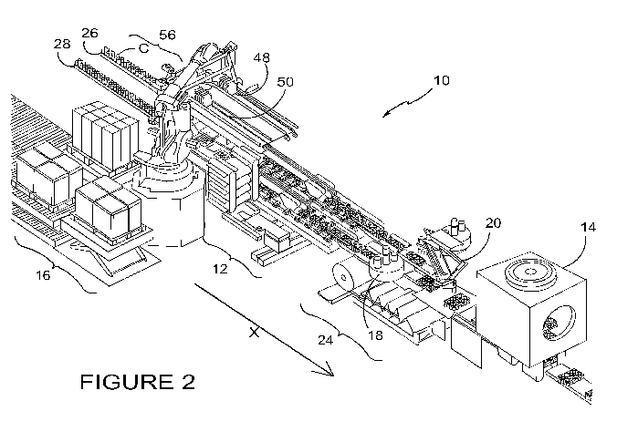
Fig. 2 shows a perspective view of an exemplary packaging line according to a
first
embodiment of the invention;
-4-
SUBSTITUTE SHEET (RULE 26)
CA 02713435 2010-07-28
WO 2009/097546 PCT/US2009/032673
Fig. 3 shows an enlarged view of an infeed end of the packaging line of figure
2;
Fig. 4 shows an enlarged view of a metering mechanism and carton forming
section of the packaging line of figure 2;
Fig. 5 shows a zoomed in view of the carton infeed, carton forming and
metering
mechanism shown in Figures 2 -4;
Fig. 6 shows an enlarged view of the metering mechanism of the packaging line
of
Figure 1 and
Fig. 7 shows an enlarged view of a tertiary packaging section of the packaging
line
of Figure 1.
For ease of reference to the features shown in the drawings, a list of
features and their
corresponding reference numeral is provided below:
Reference Feature Reference Feature
numeral numeral
X Direction of travel of articles 50 Second hopper for carton blanks
and packages on packaging line
C Primary articles 52 Lift for case packer blanks
4 Empty pallet (used for tertiary 54 Hopper for tertiary blanks
carton blanks)
6 tertiary carton blanks 56 infeed end
8 secondary carton blanks 58 rotary vacuum mechanism
Packaging Line 60 Suction cups
12 tertiary carton infeed 62 Star wheel
mechanism
14 finishing device 64 Grouping mechanism
16 auto-loading assembly 66 Delay mechanism
18 Transfer robot 68 Finishing mechanism
Robot rotator 70 Loading mechanism
24 secondary package to tertiary 72 Lifting arm
package loading section
26 First conveyor 74 former
28 Second conveyor 76 Single lug
pallet loaded with secondary 78 Tertiary blank conveyor
carton blanks
32 Conveyor for supplying a full 80 Completed secondary package
pallet of secondary carton
blanks
34 Conveyor for supplying full 82 Group of two pairs of completed
pallet of tertiary carton blanks secondary packages
36 Conveyor for empty pallets 84 Outer endless drive means
-5-
SUBSTITUTE SHEET (RULE 26)
CA 02713435 2010-07-28
WO 2009/097546 PCT/US2009/032673
38 First pallet lift 86 inner endless drive means
40 Second pallet lift 88 Spacer elements
42 first stream of primary articles 90 bars
44 Second stream of primary 92 Cam path
articles
46 pallet loaded with tertiary 94 Outer grouping mechanism
carton blanks
48 First hopper for carton blanks 96 Inner grouping mechanism
DETAILED DESCRIPTION OF EXEMPLARY EMBODIMENTS
A packaging line of the present invention will be described with general
reference to each of
the Figures 2 - 7. The present invention provides for the efficient packaging
of primary articles
such as cans or bottles (C) into secondary cartons, such as the exemplary top-
gripping clips 8a,
8b (as shown in Figures 1A and 1B) by utilising two incoming streams of
articles. The articles on
each incoming stream are processed simultaneously thus doubling the output
compared to a
single article stream packaging machine running at an equivalent linear speed.
The packaging line 10 of the present invention is shown in Figure 2. The
packaging line
comprises an infeed end generally denoted by reference 56; an auto-loading
assembly
generally denoted by 16 for loading secondary carton blanks 8 and tertiary
carton blanks 6; a
tertiary carton infeed mechanism, generally denoted by reference 12; a
secondary package 8 to
tertiary package 6 loading section generally denoted by reference 24 and a
finishing device 14.
The packaging line 10 accommodates primary articles C conveyed in two streams
on a first
conveyor 26 and accommodates primary articles C conveyed in two streams on a
second
conveyor 28. The first and second conveyors, 26, 28 receive, at one end,
primary articles C from
the output end of a bottling or filling line and deliver the articles C, at
their other end to the
infeed end 56 of the packaging line 10. The conveyors 26, 28 may be of
adjustable width to
enable a variety of articles C (such as 330m1 cans to 500m1 bottles) to be
accommodated by the
packaging line. In a preferred embodiment, each of the first and second
conveyors 26, 28 is
sized to accommodate two primary articles C side-by-side. A first stream of
primary articles C is
denoted in Figure 3 by reference 42 and a second stream of primary articles C
is denoted by 44.
-6-
SUBSTITUTE SHEET (RULE 26)
CA 02713435 2010-07-28
WO 2009/097546 PCT/US2009/032673
Secondary cartons 8a and 8b are structured to accommodate four and six cans C
arranged in
2x2 and 2x3 configurations respectively. It will be realised upon reading the
following
description with reference to the drawings that the secondary packaging clips
8a and 8b are
illustrative examples of secondary packages or secondary carton wrappers and
it is envisaged
that the packaging machine of the present embodiment and other embodiments can
accommodate different types of secondary packages, (more generally indicated
in Figures 2 - 8
by reference numeral 8) for containing, as well as cans, other primary
articles such as bottles
and for example plastic dairy pots. Such primary articles may be contained in
the secondary
cartons in variety of configurations. The direction of travel of the primary
articles C is denoted
by arrow X.
To consistently provide secondary carton blanks 8 and tertiary carton blanks 6
(see Figure 3) to
first and second carton hoppers 48, 50 and tertiary carton lift 52 and
tertiary carton hopper 54,
an auto-loading assembly 16 is provided. The auto-loading assembly 16 is most
clearly shown in
Figure 3. The auto-loading assembly 16 comprises a loading mechanism 70, a
conveyor 32 for
supplying pallets loaded with secondary carton blanks 8; a conveyor 34 for
supplying pallets
loaded with tertiary carton blanks 6; a conveyor 36 for removal of empty
pallets 4; a first pallet
lift 38 and a second pallet lift 40.
The auto-loading assembly 16 is compact and therefore minimises the amount of
floor space
required to supply pallets loaded with secondary and tertiary carton blanks
30, 38. Additionally,
by automating this process, the need for an operator is alleviated. The auto-
loading assembly
16 operates by the conveyors 32 and 34 supplying pallets 30 loaded with
secondary carton
blanks 8 and pallets 46 loaded with tertiary carton blanks 6 respectively. At
the end of each
conveyor 32, 34 a lift 40, 38 is provided. When a lift 40, 38 is not holding a
pallet 30, 46, a
loaded pallet 30, 46 is supplied by the appropriate conveyor 32, 34. The
loaded pallet 30, 46 is
in this embodiment moved from the end of the supply conveyor 32, 34 onto the
associated
adjacent lift 40, 38 by the loading mechanism 70. In other embodiments a
transfer means
connected to the lift 40, 38 is used to transfer a pallet 30 loaded with
secondary carton blanks 8
and pallets 46 loaded with tertiary carton blanks 6 to the associated lift 40,
38.
Once a pallet 30 loaded with secondary carton blanks 8 and/or a pallet 46
loaded with tertiary
carton blanks 6 is disposed on a lift 40, 38, the loading mechanism 70 (fitted
with an articulated
lifting arm 72) picks up a stack of blanks 8 or 6 using an articulating
lifting arm 72 and loads the
blanks 8; 6 onto the appropriate hopper 48/50 or 52 respectively. Once
sufficient loading
repetitions have been completed and a pallet emptied of secondary or tertiary
carton blanks 6,
-7-
SUBSTITUTE SHEET (RULE 26)
CA 02713435 2010-07-28
WO 2009/097546 PCT/US2009/032673
8, the lift 40, 38 holding the empty pallet 4 is lowered substantially to the
same height as the
conveyor for empty pallets 36. The empty pallet is transferred, in this
embodiment by the
loading mechanism onto the conveyor for empty pallets 36 which is operable to
remove the
empty pallet(s) away from the auto-loading assembly 16. The pallet conveyors
32, 34, 36 are
controlled using a programmable logic controller and therefore no human
operator of the
machine is required in this area.
The outward conveyor 36 for removal of empty pallets 4 is disposed below the
conveyor 34 for
supplying pallets 46 loaded with tertiary carton blanks 6. This means that the
supply and
removal mechanism are accommodated within the same floor space and thereby
minimise the
amount of floor space required to supply loaded pallets and remove loaded
pallets. This
compact solution reduces the area required by the packaging line 10.
It is envisaged that in other embodiments, the outward conveyor 36 is disposed
below the
other conveyor 32 for supplying pallets 30 loaded with secondary cartons 8. In
yet a further
embodiment, both inward supply conveyors 34, 32 have their own outward
conveyor 36.
However, it is most advantageous to require only one outward conveyor 36
servicing the two
inward conveyors 32, 34. A further advantage of the present invention is
gained because the
tertiary carton lift 5 and tertiary carton hopper 54 are disposed within
operable reach of the
loading mechanism 70. The loading mechanism 70 can supply blanks 8 to both
hoppers 48, 50
for the secondary blanks and to the tertiary carton lift 52 that in turn
supplies the tertiary
carton hopper 54. The compact nature of the loading mechanism 70 and its
versatility enables
the efficient supply of blanks 6, 8 to the packaging line. In known packaging
machines a tertiary
packaging assembly is provided as a separate assembly to the secondary
packaging assembly or
is provided so far down stream of the supply for the secondary blanks that
separate tertiary
blank 6 supply is required. Beneficially, the packaging line of the present
invention is structured
and arranged such that the supply and infeed of the secondary carton blanks is
situated in close
proximity to the supply and infeed of tertiary carton blanks and therefore a
single loading
mechanism 70 can efficiently serve them both, thus increasing efficiency (by
virtue of requiring
less components and/or machine operators) and a more compact packaging line
10.
Meanwhile, the two incoming streams of articles 42, 44 are supplied with
regular line pressure
by star wheels 62. Star wheels are known in the art for regulating article
flow. In this
embodiment four star wheels are used on for each side of each incoming stream
of articles 42,
44. In other embodiments where one or each stream comprises only a single line
of articles the
-8-
SUBSTITUTE SHEET (RULE 26)
CA 02713435 2010-07-28
WO 2009/097546 PCT/US2009/032673
number of star wheels may be reduced. In an alternative embodiment, where
greater than two
incoming streams of articles are accommodated the number of star wheels is
greater than four.
In the present embodiment, each star wheel 62 is provided with its own
independent driver,
preferably a servo-motor. By having independently driven star wheels, the
packaging line
remains fully adjustable in order to ensure synchronised incoming streams 42,
44.
The metering mechanism 64 (described below) groups the incoming streams of
articles 42, 44
into the required configuration. In the example being described and
illustrated the secondary
carton blanks 8 hold 6 articles C in a 2x3 configuration (see Figure 1B). The
metering mechanism
64 of the present embodiment is operable on each side of each incoming stream
of articles 42,
44 and separates the articles C into groups of 2x3 articles.
Once the first and second hoppers 48, 50 have been supplied with secondary
carton blanks 8,
and in time of the assembly of a first group of articles C, each of the first
and second hoppers
48, 50 simultaneously supplies an individual blank to a rotary vacuum
mechanism 58 which
through the use of vacuum suction cups 60 (known in the art) deposits a blank
8 simultaneously
onto a group of articles C in each incoming stream 42, 44. This is illustrated
in Figure 5. In this
illustrated embodiment, a single rotary vacuum mechanism 58 is used to supply
blanks 8 to
each of the incoming streams 42, 44. This simplifies the processing and
minimises the number
of required motors. The need to synchronise two independently driven rotary
vacuum
mechanisms that could be used, one to deposit blanks 8 on groups formed in one
incoming
stream 42 and the other to deposit blanks 8 on groups formed in the second
incoming stream
44 is therefore alleviated. However, in an envisaged embodiment two
independently driven
rotary vacuum mechanisms are used where each incoming stream 42, 44 comprises
different
articles C and C' (not shown). This optional feature whilst incorporating a
slight increase in
complexity provides the advantage that the packaging line 10 can offer a
greater degree of
flexibility.
Subsequent groups of articles are created as both streams of articles 42, 44
are conveyed
downstream of the infeed 56. In this embodiment the secondary cartons are
placed upon a
group of articles by means of a former 74. In other embodiments the 2x 3
former is replaced
with an appropriate former for the configuration of the cartons being
packaged. In other
embodiments a former is not used, as such a former is entirely optional.
-9-
SUBSTITUTE SHEET (RULE 26)
CA 02713435 2010-07-28
WO 2009/097546 PCT/US2009/032673
The grouping mechanism will now be described with specific reference to figure
6. The first and
second infeed streams of articles 42, 44 each comprising articles in side by
side abutting
relationship is introduced into each infeed end of the grouping mechanism 64.
As mentioned
above, the line pressure of the articles C is preferably controlled by infeed
star wheels 62 as is
well known. The article grouping mechanism 64 groups the correct number of
articles C per
carton as described below with the mechanism also controlling the flow of
articles C, so that
they can be coupled with the cartons at the same rate of carton flow
downstream of the
grouping mechanism 64.
The grouping mechanism 64 comprises a grouping assembly 94 positioned on each
side of the
article conveyor. Each grouping assembly 94 is similar in construction; first
the outer grouping
assembly 94 will be described and then an inner grouping assembly 96
(comprising two
grouping assemblies disposed in back-to-back relationship) will be described.
The assembly 96 includes a plurality of spacer elements 88 mounted on an
endless conveyor
comprising a spaced pair of endless chains 84. In this embodiment, each spacer
element 88
includes an engagement portion comprising three partly cylindrical recesses,
positioned
adjacent one another. If the articles to be packaged are the same size then
each recess has an
identical length and is shaped substantially to conform to a peripheral wall
portion of a bottle
or can C (or other article) with which the recess is to engage. The spacer
elements 88 can be
grouped into pairs with leading or trailing spacer elements.
Cam followers project from the underside of body portions of the spacer
elements (not shown).
Each spacer element 88 is connected to the endless chains 94 by suitable
attachment means. In
this embodiment, the body portion of each element is slidably mounted on a
pair of bars 98
extending between and secured to the endless chains 94 (only one visible).
This arrangement
permits transverse movement but prevents a rotational or longitudinal movement
of the spacer
elements 88 with respect to the endless chains 94.
The endless chains 94 are mounted onto guide tracks of the assembly 94. The
assembly 94
further comprises a cam track 92 to receive the cam followers extending from
each spacer
element 88. The endless chains 94 are driven by a motor, for example a servo
motor (not
-10-
SUBSTITUTE SHEET (RULE 26)
CA 02713435 2010-07-28
WO 2009/097546 PCT/US2009/032673
shown) through a drive shaft. As each spacer element 88 moves downstream along
the path of
the cam track 92 the recesses are maintained in a plane parallel to the
direction of motion of
the articles C on the article conveyor 26, 28.
In operation continuous downstream motion of the endless chains 94 causes the
leading spacer
element 88 to be deployed into engagement with the articles C before a
trailing spacer
element, thus causing the mechanism to form two groupings of articles having a
maximum
length of three articles and a relatively short pitch therebetween.
Optionally, in order that the grouping mechanisms 94, 96 can be used to
produce two
groupings of between one and three articles length in the flow direction, or
alternatively one
grouping comprising between four and six articles length in the article flow
direction, the
mechanism has a second mode of operation.
To this end, in addition to the primary cam track 92, (that brings the spacer
elements 88 into
contact with the articles C to achieve the desired grouping), a secondary cam
track (not shown)
is in another embodiment provided such that spacer elements 88 following the
secondary cam
track are delayed from being deployed into contact with the articles C. An
adjustment or
selecting means is provided to select whether the leading spacer element 88
enters the
secondary cam track according to the particular mode of operation. A blocking
member is
preferably provided at the exit of the secondary cam track to ensure that the
trailing
engagement member (not depicted) does not partially retract when passing the
opening or
catch in the opening.
The inner grouping assembly 96 has been structured and arranged to optimize
the space
required by this section of the packaging line 10. The spacer elements 88 on
the inner grouping
assembly 88 are mounted onto each end of the double ended bars 90 that extend
between and
are secured to the endless chains 86. In this way the inner grouping assembly
96 is formed from
two of the outer grouping assemblies arranged back-to-back but with the
significant difference
that a spacer element is mounted onto each end of the bars 92 and only two
endless chains 86
are needed to drive two opposed spacer elements 88, whereas in the outer
grouping assembly
94, two endless chains (or other suitable drive means) are required for only a
single headed
assembly. The inner assembly 96 is therefore narrower than the sum of the
widths of two outer
- 11 -
SUBSTITUTE SHEET (RULE 26)
CA 02713435 2010-07-28
WO 2009/097546 PCT/US2009/032673
assemblies 94 such that a dual ended metering system is operable between the
two processing
streams 26 and 28. It is envisaged that in other embodiments the spacer
elements on each side
of the dual-ended metering system could be differently configured, arranged
and/or shaped in
order to accommodate different styles of articles in each of the two lanes 42,
44.
The grouping of articles C is, as described above, adaptable such that groups
of between 1 and
6 articles can be created (for 4 - 6 articles a dual cam track arrangement is
needed and two
adjacent spacing elements 88 operate as a pair, this is not shown). The
grouping of the articles
C is an optional feature of the general packaging line 10 and metering may be
done in other
ways, however for the dual lane packaging line described, the double sided
grouping
mechanism 96 offers a compact solution that is adaptable to different sizes of
articles and can
accommodate cartons requiring a variety of configurations. Because the
grouping mechanism
96 is narrower than the sum of the widths of two outer assemblies 94, the
overall width of the
packaging line 10 is kept sufficiently narrow that collated carton groups 82
easily can be
transferred onto a tertiary blank 6 (see description below).
Additionally, it is envisaged that in other embodiments, the spacing elements
on one side of the
grouping assembly 96 might differ in shape and/or size than those of the other
side to
accommodate different types of article being provided on the first and second
processing lines
26, 28. In such an embodiment the final tertiary package would contain say two
packs of cans
and two packs of bottles.
The carton package is completed by passing the grouped articles and secondary
carton through
finishing mechanism 68, in this case a pair of rollers 68 which apply pressure
to each side of a
package to ensure that the side portions of the carton have been secured in
place. As discussed
above, the precise nature of the carton to be packaged is optional and as such
the use of pair of
rollers 68 is entirely optional. The completed package 80 is then transferred
to a delay
mechanism comprising a single lug 76, lug chain. As completed packages 80 are
transferred to
the delay mechanism 66 the travel of a leading package 82 is slowed and an
immediately
trailing package catches up. The slowing of a package to create a group of 2
packages is
achievable with a system of belts, wheels, a robot or chains with and cam path
such that
articles are regrouped into 2x6 articles (2 packages of articles arranged in a
2x3 configuration
or 3 packages arranged in a 2x2 configuration) and is not limited to the
mechanism described
herein.
-12-
SUBSTITUTE SHEET (RULE 26)
CA 02713435 2010-07-28
WO 2009/097546 PCT/US2009/032673
At the same time as the carton packages 80 are being assembled, tertiary
carton blanks 6 are
transferred, along a conveyor 78 from the lift for case packer blanks 52 onto
the tertiary carton
hopper 54 and then conveyed underneath and between the grouping mechanisms of
the first
incoming stream 42 and second incoming stream 44. By using two tiers, the
linear dimension of
the packaging line is reduced and made more compact. The delivery of tertiary
carton blanks 6
is synchronized with the assembly of the carton packages 80 such that the
tertiary carton
blanks arrive proximate the level of the grouped packages 82 and between the
two processing
streams (see Figure 8). Almost immediately the construction and grouping of a
pair of packages
80 in each processing stream is completed a tertiary blank 6 is supplied to
receive them. A
transfer robot 18 is provided either side of processing streams 42, 44 to move
the collated pair
of packages 82 of each processing stream 42, 44 onto the tertiary blank 6
disposed
therebetween (as shown in Figure 7). By using robots to pick and place the
collated packages 82
in this way the pitch of the packaging line 10 is maintained and the tertiary
packaging assembly
is formed as an integral part of the packaging line 10 without the need for
conveying the
finished packages 82 to a separate sub-assembly for transferring the collated
secondary
packages to a tertiary package.
In an optional final step in the processing carried out by the packaging line
10 described, the
tertiary packages are transferred by a rotator robot 20 and transferred to a
finishing device, in
this embodiment a shrink wrapping device.
The construction of the carton 8 as illustrated in the Figures provides an
illustration of how the
benefits of the present invention can be applied to a specific secondary
carton formation and
tertiary packaging into a crate. It is envisaged that cartons formed by a
different series of
sequential folding operations, preferably in a straight line machine, could be
assembled by a
packaging machine according to the invention without necessarily involving the
grouping,
forming and finishing steps described. As such the invention should not be
construed as being
limited in application to the specific carton or article types described or
folding and
construction process described and these aspects may be altered according to
particular
manufacturing requirements.
Upon reading the foregoing it will be understood that the present invention
provides
improvements in the field of packaging machinery. In a known single line
packaging machine,
articles are collated using a secondary clip, the grouped articles are then
transferred along a
conveyor to a second in-line sub-assembly, a divider, where the single line is
split so that two
-13-
SUBSTITUTE SHEET (RULE 26)
CA 02713435 2010-07-28
WO 2009/097546 PCT/US2009/032673
side-by-side packages can be transferred to a third in-line sub assembly.
Tertiary package
blanks are supplied to the third in-line subassembly and the secondary
packages are loaded into
the tertiary packs which are then conveyed along to a fourth in-line
subassembly where shrink
wrap finishing is conducted. The average length of such a machine is 300m,
whereas the
aforedescribed packaging line of the present invention is only 120m. The
single line machine is
known to run at an average linear operational speed of 760m per minute whereas
the double
line integrated packaging line of the present invention only needs to run at
an average linear
operational speed of 380m per minute to produce 300 cartons per minute
(comprising 4
articles in a 2x2 configuration) and 50 tertiary packages (comprising 24
articles). In summary,
the present invention provides a compact and efficient machine having a high-
throughput yet
being less than half the length of an equivalent known machine and able to
operate at half the
linear running speed of known machines without compromising the throughput.
These
advantages are gained by providing a dual line machine with simultaneous
processing of two
(or more) lanes of articles; a compact (narrow and short) metering and
grouping mechanism
that services both lanes of articles simultaneously; an auto-loader mechanism
that services
both the secondary blank hoppers and the tertiary hopper; an outward conveyor
disposed in
vertical alignment with the pallet delivery conveyor (to reduce the linear
dimension of machine
line); a tertiary carton in-feed/transfer disposed in vertical alignment with
the secondary
package formation (to reduce the linear dimension of machine line) and
positioned such that
the tertiary package blanks meet the packaged secondary articles within only a
few carton
pitches (preferably one) of the completion of the secondary packages; and
immediate transfer
of tertiary packages to finishing device.
It can be appreciated that various changes may be made within the scope of the
present
invention, for example in other embodiments the size and shape of the articles
and cartons
packaged and style of secondary and tertiary packages will differ from that
illustrated herein. In
other embodiments of the invention it is envisaged that the finishing device
is omitted or in
other embodiments where the finishing device is present, the finishing process
may be other
than shrink wrapping.
It is also envisaged that whereas processing on two lines simultaneously has
been described, in
other embodiments, three incoming lanes or processing lanes are provided and
each are acted
upon simultaneously. In such an embodiment the metering device may comprise
two dual
sections and two single sections. Additionally, the in feed of the tertiary
package in such an
embodiment may be disposed between the first and second and/or second and
third lanes or
alternatively, may be aligned with the end of the second lane such that
cartons from the second
-14-
SUBSTITUTE SHEET (RULE 26)
CA 02713435 2010-07-28
WO 2009/097546 PCT/US2009/032673
lane are immediately fed onto the tertiary carton blank and the secondary
cartons from the
first and third processing lanes are transferred by the transfer robot onto
the tertiary package.
However, optimum benefit in reduced complexity is gained by using two
processing lines and
although it is envisaged that more than two processing lines can be used, it
will be understood
that the advantage of reducing the linear dimension will be offset by the
necessary increased
width of such a packaging machine.
It will be recognised that as used herein, directional references such as
"in", "end", "up",
"down", "side" do not limit the described feature to such orientation, but
merely serve to
distinguish relative orientations one another.
-15-
SUBSTITUTE SHEET (RULE 26)