Note: Descriptions are shown in the official language in which they were submitted.
CA 02713802 2010-08-25
LUBRICATION SYSTEM WITH POROUS ELEMENT
TECHNICAL FIELD
[0001] The application relates generally to lubrication systems providing
lubricant to
rotating components and, more particularly, to lubrication systems for gas
turbine engines.
BACKGROUND
[0002] In a lubrication system of a gas turbine engine, the used lubricant
expelled from the
rotating components, such as the main bearings, meshed gears of the accessory
gearbox and
centrifugal air/oil separator, has an increased velocity and circulates along
a swirling path,
such that the used lubricant typically has a tendency to remain within the
cavity containing
the rotating component for a given period of time instead of circulating
directly to the drains
of the scavenge system. As such, the quantity of lubricant which remains in
circulation within
the lubrication system generally increases the weight of the engine and the
size of the
reservoir required to contain the lubricant when the engine is at rest.
Accordingly,
improvements are desirable.
SUMMARY
[0003] In one aspect, there is provided a lubrication system for a gas turbine
engine, the
lubrication system comprising a supply source containing a lubricant, at least
one partial or
complete enclosure each defining a cavity containing at least one respective
rotating
component receiving a flow of the lubricant, a pressure system including a
supply fluid
connection defined between the supply source and each cavity, the pressure
system flowing
the lubricant from the supply source to each rotating component, a scavenge
system including
a scavenge fluid connection defined between each cavity and the supply source,
the scavenge
system scavenging the lubricant from each cavity, and at least one porous
element located in
the at least one cavity across a path taken by a portion of the lubricant
expelled from the at
least one respective rotating component such that the portion of the lubricant
circulates
therethrough, the at least one porous element being made of a material
resistant to a
-1-
CA 02713802 2010-08-25
temperature of the lubricant, the at least one porous element reducing a
velocity of the portion
of the lubricant circulating therethrough.
[0004] In another aspect, there is provided a gearbox comprising a plurality
of rotating
meshed gears transferring power from a driving shaft to a driven shaft, a
casing enclosing a
gearbox cavity surrounding the meshed gears, a lubrication system including at
least one
supply fluid connection providing lubricant to the gearbox cavity and to the
meshed gears and
at least one scavenge fluid connection circulating the lubricant out of the
gearbox cavity, and
at least one porous element extending within the gearbox cavity across a path
of a portion of
the lubricant being projected by the rotating meshed gears, the at least one
porous element
reducing a kinetic energy of the lubricant circulating therethrough to
facilitate direction of the
lubricant toward the at least one scavenge fluid connection.
[0005] In a further aspect, there is provided a method of reducing a period of
time
necessary for lubricant to circulate from rotating components lubricated by a
lubrication
system back to a supply source of the lubricant, the method comprising
reducing a kinetic
energy of a portion of the lubricant expelled by at least one of the rotating
components by
circulating the portion of the lubricant through at least one element made of
porous material,
and redirecting the portion of the lubricant exiting the at least one element
toward a
connection with the supply source.
DESCRIPTION OF THE DRAWINGS
[0006] Reference is now made to the accompanying figures in which:
[0007] Fig. 1 is a schematic cross-sectional view of a gas turbine engine;
[0008] Fig. 2 is a diagram of a lubrication system which can be used in a gas
turbine
engine such as shown in Fig. 1;
[0009] Fig. 3 is a schematic cross-section of a part of an accessory gearbox
which can be
used in a gas turbine engine such as shown in Fig. 1;
[0010] Fig. 4 is a schematic cross-section of part of an alternate accessory
gearbox;
-2-
CA 02713802 2010-08-25
[0011] Fig. 5 is a schematic cross-section of a main bearing cavity of a gas
turbine engine
such as shown in Fig. 1; and
[0012] Fig. 6 is a schematic cross-section of a reduction gearbox which can be
used in
another type of gas turbine engine.
DETAILED DESCRIPTION
[0013] Fig.1 illustrates a gas turbine engine 10 of a type preferably provided
for use in
subsonic flight, generally comprising in serial flow communication a fan 12
through which
ambient air is propelled, a compressor section 14 for pressurizing the air, a
combustor 16 in
which the compressed air is mixed with fuel and ignited for generating an
annular stream of
hot combustion gases, and a turbine section 18 for extracting energy from the
combustion
gases.
[0014] The fan 12 is drivingly interconnected to low pressure rotor(s) of the
turbine
section 18 through a low pressure shaft 23, and the high pressure rotor(s) of
the compressor
section 14 is/are drivingly connected to high pressure rotor(s) of the turbine
section 18
through a high pressure shaft 24 concentrically surrounding the low pressure
shaft 23.
[0015] The gas turbine engine includes an accessory drive assembly 20 which
includes an
accessory gearbox (AGB) 22. Although not shown, the accessory drive assembly
20 can also
include a pump assembly and/or a starter generator. The accessory drive
assembly 20 is
driven by the high pressure shaft 24 via an accessory shaft 26 which drivingly
interconnects
the high pressure shaft 24 and the accessory gearbox 22, for example through a
first bevel
gear (not shown) located at one end of the accessory shaft 26 and engaged with
a
corresponding bevel gear (not shown) of the high pressure shaft 24, and a
second bevel gear
28 (see Fig. 3) located an opposed end of the accessory shaft 26 and engaged
with a
corresponding bevel gear 30 of the accessory gearbox 22.
[0016] Referring to Fig. 2, the gas turbine engine further includes a
lubrication system 40
for lubricating and cooling rotating components of the engine 10, such as for
example the
main bearings supporting the low and high pressure shafts 23, 24 and the gears
of the
-3-
CA 02713802 2010-08-25
accessory gearbox 22. The lubrication system 40 includes a supply source 42
which is for
example a reservoir, and at least partial or complete enclosure each defining
a cavity
containing at least one respective rotating component requiring lubrication.
The cavities
include a main bearing cavity 44 surrounding each of the main bearings, an
accessory
gearbox cavity 46 defined by the casing of the accessory gearbox 22, and
optionally one or
more cavities 48 each surrounding one of any other rotating component of the
engine
requiring lubrication.
[0017] The lubrication system 40 also includes a pressure system 50 including
a supply
fluid connection 52 defined between the supply source 42 and the cavities 44,
46, 48 to flow
the lubricant to the rotating components, and a scavenge system 54 including a
scavenge fluid
connection 56 draining lubricant from the cavities 44, 46, 48 to scavenge the
used lubricant
from the rotating components back to the supply source 42, either directly or
after circulation
through an air/oil separator 58. In the embodiment shown, the air/oil
separator 58 is located
within the accessory gearbox cavity 46 and driven by a shaft thereof.
[0018] In use, the lubricant in the supply source 42 is directed by the
pressure system 50
under pressure, for example with the help of one or more pumps 60, into the
main bearing
cavities 44 of the main shaft of the aircraft engine, the accessory gear box
cavity 46, and any
other cavity 48 requiring lubrication. The lubricant is circulated through the
respective supply
fluid connection 52 to be distributed to the rotating components.
[0019] During the lubrication of the main bearing cavities 44, the lubricant
is mixed with
relatively hot compressed air streams used to pressurize air seals of the main
bearing cavities,
resulting in a used lubricant in the form of an air/oil mixture. Such air
seals can be labyrinth
seals or other types of air seals. The use lubricant is also hot since the
lubricant absorbs heat
energy produced in the main bearing cavities as a result of the very high
speed rotation of the
main shaft of the aircraft engine, and further mixes with the relatively hot
compressed air
streams. In order to remove the air contained in the used lubricant, the used
lubricant is
circulated through the separator 58, which is for example a centrifugal
separator.
-4-
CA 02713802 2010-08-25
[0020] A first portion 54a of the scavenge system 54 thus collects the used
lubricant from
the main bearing cavities 44 and other cavities 48 and flows it into the
accessory gearbox
cavity 46 through the respective scavenge fluid connection 56. Within the
accessory gearbox
cavity 46, the used lubricant reaches the inlet of the air/oil separator 58.
Due to the
centrifugal and coalescent effects within the separator 58, the liquid oil
circulating
therethrough is discharged to the accessory gearbox cavity 46, after which it
accumulates at a
lower portion of the cavity where a second portion 54b of the scavenge system
54 collects it
and returns it to the supply source 42 through the corresponding scavenge
fluid connection
56.
[0021] The first and second portions 54a,b of the scavenge system 54 circulate
the
lubricant with the help of pump(s) (not shown), gravity and/or blowdown.
[0022] The air contained in the used lubricant within the centrifugal
separator 58 and
under the pressure differential is discharged through a passage 62 to outside
of the engine.
[0023] The lubricant discharged from the separator 58 is still relatively hot,
and then
becomes much cooler after the following scavenging process and by being mixed
with the
lubricant stored in the supply source 42. A cooling step is indicated at 64,
which does not
necessarily indicate a specific cooling device.
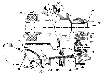
[0024] Referring to Fig. 3, an accessory gearbox cavity 46 according to a
particular
embodiment is shown, where a number of porous elements 70a,b,c,d are installed
across a
path of the used lubricant expelled from the separator 58 and/or meshed gears
28, 30 such as
to reduce the velocity of the expelled lubricant. A first porous element 70a
is shown, installed
on a surface of a flange 72 positioned to receive the lubricant expelled from
the centrifugal
separator 58. A second porous element 70b is installed on a surface of a wall
74 of the casing
defining the accessory gearbox cavity 46, upon which the lubricant deflected
by the flange 72
and the lubricant expelled by the meshed gears 28, 30 is projected. A third
porous element
70c is installed on a surface of a bottom wall 76 of the casing defining the
accessory gearbox
cavity 46, upon which the used lubricant is collected before flowing to a
drain 78
communicating with the respective fluid connection 56 of the scavenge system
54 (see Fig.
-5-
CA 02713802 2010-08-25
2). A fourth porous element 70d is installed across a bottom of the accessory
gearbox cavity
46 and over the drain 78 such that used lubricant flowing to the drain 78
flows through the
fourth porous element 70d.
[0025] The porous elements 70a,b,c,d are placed on solid redirecting elements,
e.g. casing
wall, flange, etc., such that the used lubricant flow through the porous
elements before
reaching the redirecting elements, or alone across the cavity within the path
of the used
lubricant such that the used lubricant circulating across the cavity flows
therethrough. The
porous elements reduce the velocity of the lubricant circulating therethrough,
thus "calming"
the flow of lubricant and allowing the used lubricant to return to the
scavenge system more
quickly. Typically, walls, flanges or other solid redirecting surfaces attempt
to redirect the
flow toward the drain without substantially slowing it or reducing its energy,
and as such an
important quantity of the lubricant generally "bounces back" away from the
intended
redirection direction. By reducing the kinetic energy of the used lubricant,
the porous
elements reduce the quantity of used lubricant bouncing away from the intended
redirection
direction, such that the used lubricant is more quickly redirected toward the
drain.
[0026] In a particular embodiment, only one of the porous elements 70a,b,c,d
shown is
provided, while in an alternate embodiment, the porous elements 70a,b,c,d are
provided in
any combination of two or more of the locations shown. Other locations are
also possible, as
long as the porous elements are located across the path of the used lubricant
expelled from
the rotating component(s) such that the used lubricant can circulate
therethrough.
[0027] Fig. 4 shows a top portion of an accessory gearbox cavity 146 according
to an
alternate embodiment, where an air/oil separator 158 is provided on a shaft
supporting a
lower gear 182 which is meshed with an upper gear 180. The meshed gears 180,
182 are
partially surrounded by two porous elements 170a,b. A first porous element
170a is provided
along a top portion 184 of the casing wall defining the gearbox cavity 146.
The first porous
element 170a, like the wall portion 184 it is supported on, has a
substantially inverted U-
shape such as to surround a portion of the upper gear 180. A second porous
element 170b is
provided along a lower portion 186 of the casing wall, with the second porous
element 170b
-6-
CA 02713802 2010-08-25
and wall portion 186 having a substantially Z-shape. As such, the second
porous element
170b extends in proximity of the meshed portions of the gears 180, 182 as well
as along the
wall receiving part of the used lubricant expelled from the separator 158. In
a particular
embodiment, only one of the two porous elements 170a,b is provided. In an
alternate
embodiment, any combination of two or more of the porous elements 70a,b,c,d
170a,b,
previously described and/or of one or more porous elements in any other
adequate location
within the path of the used lubricant is provided.
[0028] Referring to Fig. 5, a main bearing cavity 44 according to an exemplary
embodiment is shown. A bearing 288 supports one of the low pressure and high
pressure
shafts 23, 24, and is maintained in place by a housing 290. A drain 278 is
defined at the
bottom of the bearing cavity 44, which is in communication with the respective
scavenge
fluid connection 56 of the scavenge system 54 (see Fig. 2). A porous element
270 is provided
along the bottom wall 276 of the bearing cavity 44 and across the drain 278,
such that the
used lubricant projected at the bottom of the cavity 44 circulates through the
porous element
270.
[0029] Fig. 6 shows an example of porous elements being applied to another
type of
gearbox, which in this case is a reduction gearbox 392 of a turboprop or
turboshaft engine.
The reduction gearbox 392 includes a plurality of meshed gears 394 contained
within a
gearbox cavity 346 defined by a casing surrounding the meshed gears, and a
drain 378 is
provided at the bottom of the cavity 346 in fluid connection with a
corresponding scavenge
system (not shown). A plurality of porous elements 370a,b,c,d are provided
around the
meshed gears 394 such as to receive the used lubricant expelled thereby. First
and second
porous elements 370a,b extend along upper walls 384 of the casing and in
proximity of
adjacent ones of the gears 394. A third porous element 370c has a
substantially U-shape and
extends along side and bottom walls 374, 376 of the casing and across the
drain 378 such that
the used lubricant flows through the third porous element 370c before reaching
the scavenge
system. The third porous element 370c is preferably shaped to follow the
contour of adjacent
ones of the gears 394, such as to receive a maximum of the used lubricant
expelled
-7-
CA 02713802 2010-08-25
therefrom. A fourth porous element 370d extends from the third porous element
370c and can
be integral therewith, and extends between adjacent spaced apart ones of the
gears 394. As
such, all of the gears 394 are partially surrounded by at least one of the
porous elements
370a,b,c,d. As above, the porous elements 370a,b,c,d can be provided in any
one or any
combination of two or more of the shown locations, or in any other locations
where the used
lubricant expelled from the meshed gears can circulate therethrough.
[0030] The porous elements 70a,b,c,d, 170a,b, 270, 370a,b,c,d are made of a
mesh or open
cell foam material adapted to resist to the high temperature of the lubricant
circulating
therethrough, which in a particular embodiment is about 300 F. Such a material
can include,
for example, silicon carbide, reticulated vitreous carbon (RVC), or any
adequate type of
ceramic or metal or combinations thereof. Preferably, the porous elements
70a,b,c,d, 170a,b,
270, 370a,b,c,d are made of aluminium mesh.
[0031] In a particular embodiment, the density of the porous elements
70a,b,c,d, 170a,b,
270, 370a,b,c,d is between 10 and 40 pores/inch inclusively, or between 6 and
8%.
[0032] The porous elements 70a,b,c,d, 170a,b, 270, 370a,b,c,d also acts to
separate some
of the air from the lubricant, thus increasing the effectiveness of the
air/oil separation process
within the lubrication system.
[0033] In a particular embodiment, several porous elements 70a,b,c,d, 170a,b,
270,
370a,b,c,d having different densities are provided within the lubrication
system, or within the
same cavity, with the porous elements receiving lubricant including a higher
proportion of air
therein having a greater density than that of the porous elements receiving
lubricant having a
lower proportion of air therein. Also, in a particular embodiment, the porous
elements
receiving lubricant having a higher velocity have a greater density than that
of the porous
element receiving lubricant having a lower velocity. For example, a porous
element located
at the top of the gearbox cavity, where the used lubricant includes more air
therein and a
higher velocity, can have a higher density than a porous element located at
the bottom of the
gearbox cavity where the lubricant contains a lower proportion of air and has
a lower
velocity. In a particular embodiment, porous elements of three different
densities are
-8-
CA 02713802 2010-08-25
provided within the lubrication system, or within the same cavity, with
densities of for
example 10, 20 and 40 pores/inch, and are distributed according to the
proportion of air
contained in the lubricant and/or the speed of the lubricant circulating in
the portion of the
lubrication system where each porous element is provided, as set forth above.
[0034] The porous elements, in reducing the velocity and calming the lubricant
circulating
therethrough, advantageously reduce the time taken by the used lubricant to
exit the cavity
and reach the scavenge system. In addition, the porous elements alone or in
combination with
a baffle or wall upon which the porous elements are provided help redirect the
used lubricant
toward the drain(s) leading to the lubrication system, thus further reducing
the time taken by
the used lubricant to reach the scavenge system. As such, the quantity of
lubricant in
circulation at a given time of operation of the lubrication system is reduced.
This, in turn,
reduces the total quantity of lubricant required, and as such the necessary
size for the supply
source (e.g. reservoir) and the overall weight of the engine.
[0035] Also, when the volume of the cavity surrounding the rotating components
is sized
below a given minimum, the lubricant generally remains "caught" within the
cavity due to its
turbulence and due to the airflow produced by the rotating components, and as
such is
prevented from dropping to the bottom of the cavity and be redirected to the
scavenge
system. The presence of the porous element, in reducing the turbulence of the
used lubricant
and the effect of the airflow produced by the rotating components on the
lubricant, allows for
a the cavity containing the rotating components to have a smaller volume while
still allowing
the lubricant to return to the bottom of the cavity. As such, in a particular
embodiment, the
presence of the porous elements allow for the cavities containing each
rotating component to
have a smaller size, thus potentially reducing the overall weight of the
engine.
[0036] The porous elements can advantageously be added to new as well as
existing
lubrication systems.
[00371 The above description is meant to be exemplary only, and one skilled in
the art will
recognize that changes may be made to the embodiments described without
departing from
the scope of the invention disclosed. For example, the porous element can also
be similarly
-9-
CA 02713802 2010-08-25
incorporated in high performance gearboxes other than those included in
aircraft gas turbine
engines, for example in the types of high performance gearboxes usable in
cars, trains and/or
boats. Still other modifications which fall within the scope of the present
invention will be
apparent to those skilled in the art, in light of a review of this disclosure,
and such
modifications are intended to fall within the appended claims.
-10-