Note: Descriptions are shown in the official language in which they were submitted.
CA 02713941 2014-03-11
-1 -
10 Apparatus for manufacturing reinforced cellular materials
TECHNICAL FIELD
The present invention relates to the technical field of manufacturing
composite
materials. In particular, the invention relates to apparatus for manufacturing
a
reinforced cellular material and for taking up a semi-finished textile product
in a
hook. Furthermore, the invention relates to a system for manufacturing
reinforced
cellular materials, as well as to a method for taking up semi-finished textile
products in a hook, for the reinforcement of cellular materials. Likewise, the
invention relates to the use of a reinforced cellular material in an aircraft,
as well
as to an aircraft comprising such a reinforced cellular material.
BACKGROUND TO THE INVENTION
Due to their good ratio of rigidity or strength to density, composite
materials, and
in particular sandwich constructions, are widely applied in many areas of
aircraft
engineering. Generally speaking, sandwich constructions are made from a top
face
sheet or face layer and a bottom face sheet or face layer, between which
layers or
sheets, for the purpose of increasing rigidity, there is a honeycomb-like core
structure formed by vertically extending cells with hexagonal cross sections.
KK:CGS:ur
= alx Mar .
CA 02713941 2010-05-20
- 2 -
The specific mechanical potential of cellular materials, when compared to such
honeycomb structures, is lower due to their structure. Nevertheless, above all
in
the manufacture of components and in the region of expanded component
characteristics, cellular materials are of interest due to their
multifunctionality for
application in sandwich constructions for structural aeronautical
applications. For
this reason various experiments are being carried out in an attempt to improve
the
mechanical characteristics of the cellular materials without incurring an
excessive
increase in density. By means of sewing techniques, the incorporation of pins,
or
by means of similar methods, the core is locally reinforced without incurring
a
considerable increase in the weight of the structure. Moreover, in various
methods
there is an option, by means of local variation in the pin density and in the
pin
angle, of tailoring the mechanical characteristics of the core structure to a
particular case of application as well as tailoring them locally. Apart from
the
mechanical characteristics that are of interest from the point of view of
statics,
these core structures in addition comprise characteristics that are very
interesting
as far as the impact or the degree of impact damage is concerned. For example,
in
reinforced cellular materials a crack-stopping effect can be detected.
Among other things in the region of thermal and acoustic insulation, as well
as in
their manufacture, these sandwich constructions comprising a high-resistance
cellular material core are associated with advantages when compared to
honeycomb structures, but they are associated with disadvantages in that they
comprise only comparatively poor mechanical characteristics. In order to
compensate for these mechanical disadvantages, sewing techniques are used by
means of which it becomes possible to incorporate fibres, fibre bundles or
threads
in high-resistance cellular material components. After a resin infiltration
process,
the regions interspersed with fibres then contribute to the mechanical
reinforcement of the cellular material.
CA 02713941 2014-03-11
- 3 -
The sewing methods that are commonly used to reinforce cellular materials
consist of penetrating a cellular material by means of a needle, and in this
process
at the same time of pulling the thread or the fibre bundles or fibres through
the
high-resistance cellular material. Two different methods are used to fix the
thread.
Firstly, by means of the sewing method known as tufting, a thread can be
pulled
through the high-resistance cellular material layer, and can be affixed to a
substrate, for example silicon rubber, situated on the opposite face. After
completion of the seam the substrate can be removed.
The second sewing method belongs to the category of double-face sewing
methods, wherein an upper thread from a face layer of the sandwich
construction
is stitched through the layer construction with a needle. Subsequently the
upper
thread is affixed, by means of a bottom thread, to the opposite face of the
layer
construction.
Due to the fact that the needle and the thread enter the cellular material at
the
same time, a hole size is generated in the cellular material, which hole size
is
larger than the diameter of the incorporated fibre quantity. For example, if
the
high-resistance cellular material is further processed, for example during
infiltration, the remaining void of the holes, which void is not filled by
fibre
bundles, is filled by the resin.
The known sewing methods have one aspect in common, namely that first a
needle penetrates the cellular material and in this process at the same time
incorporates the thread in the cellular material. In this process during
insertion in
the cellular material the thread extends parallel to, and substantially over
the entire
CA 02713941 2014-03-11
- 4 -
length of, the needle. The hole size of the insertion hole is thus determined
by the
needle diameter and the thickness of the thread.
All these known methods are associated with a disadvantage in that after
withdrawal of the needle from the cellular material the remaining hole is too
large
in relation to the thickness of the incorporated thread. This leads to a
situation in
which after infiltration with a resin the hole region that is not taken up by
fibres is
filled with resin, and consequently the improvement in the mechanical
characteristics is not implemented by the fibres, as desired, but instead,
depending
1 0 on the method, is implemented by the incorporated resin. However, the
improvement of the specific, i.e. weight-related, mechanical characteristics
is
insufficient, when compared to those of honeycomb structures, for the light-
weight construction potential necessary in aircraft engineering, so that the
use of
cellular materials reinforced in this way can only seldom be considered.
In order to illustrate the importance and the advantages of the present
invention,
the following should be added in the context of the technical field of
manufacturing reinforced materials:
Investigations of the effects of titanium pin reinforcements on the failure
pattern
of the sandwich construction have shown that in the case of reinforced
cellular
materials the area of damage clearly remains limited to the region within an
inner
row. It is thus clear that the damage is locally confined. During further
investigations the effects of the space between reinforced regions can be
determined. If, in a relative dense reinforcement, failure of the face sheets
is due
to complex interaction of local and global flexing and shear failure of the
face
sheets, when the rigidity is reduced, due to the lower reinforcement density
the
face sheet failure is dominated by bending. The damage pattern shows localised
-
CA 02713941 2010-05-20
- 5 -
damage and micro cracks in the impacted face layer, but no damage on the
reverse
face. In the region of the impact the pins that have penetrated the face
layers have
been pulled out. Furthermore, fibre rupture occurs, as does local separation
of the
core from the face layer in the region of impact. These practical results
agree well
with theoretical simulations. Also in this context CAI investigations can be
made;
they show that in the case of a non-reinforced cellular material the main
failure
mechanism consists of microbuckling of the face sheets. However, in the case
of
reinforced cellular materials, separation/release of the pins is the main
failure
mechanism. Apart from the NDT behaviour of reinforced cellular materials it is
also possible to investigate the dependencies on the reinforcement angle. One
result demonstrates that the limiting value for the introduction of damage as
a
result of pulling the pins from the face layer depends strongly on the pin
angle. In
the case of a 100 reinforcement the limiting value at which damage that is
worth
mentioning occurs is more than twice the value in the case of a 20
reinforcement.
Investigation (both experimental and by means of FEM-analysis) of the energy
absorption capacity of reinforced cellular materials subjected to pressure
loads
shows that by increasing the thickness the energy absorption capacity can be
greatly increased. It is important to ensure that the space between
reinforcement
elements is less than half the wavelength of the folds that are created in a
non-
reinforced sandwich construction of the same design.
Reinforcement by means of stiffened pins:
In industrial development projects a new core material has been developed that
corresponds to the characteristics of the 48 kg/m3 honeycomb while saving 10%
in weight. This new core comprises a light cellular carrier material that is
reinforced by thin pins in order to improve its structural characteristics.
The
reinforcing semi-finished products are thin bar-shaped elements of any desired
cross section, provided they comprise adequate inherent stiffness because
otherwise they cannot be processed. The diameter of the pins used is between
CA 02713941 2014-03-11
-6-
0.279 and 0.711 mm. Taking into account the respective materials
characteristics
the pins can be from any of the three materials categories, for example fibre-
reinforced plastic, titanium alloys, glass, NicalonTM or quartz. In the method
developed, the pins are shot, with the support of ultrasound, into the
cellular
material, and in a second step they are transformed at the surface. The
resulting
product is marketed by the trademark of K-CORTm. As an alternative to the
above
the pins can also enter the face layer. This product is commercially available
by
the name of X-CORTm. This method provides a very considerable advantage in
that the semi-finished reinforcement products can be manufactured in a
separate
process step as an endless product. Especially in the case of semi-finished
bonded
fibre fabrics, whose characteristics depend greatly on the fibre volume
content and
the fibre orientation, this is very positive. Designers thus have the option,
by
varying the local pin density, pin length, pin diameter and pin angle, to
design a
core that is optimal for each application. Possible angles range from vertical
pins
for component regions that are particularly strongly subjected to pressure, to
angles between 20 and 30 for shear reinforcement.
Reinforcement by means of dry semi-finished products:
Dry reinforcement of cellular materials is possible using various methods:
sewing
methods, winding-/braiding methods and stapling methods. The resulting
products
differ greatly both in the quality and in the flexibility of their
reinforcement.
Finishing of the dry-reinforced cellular material cores takes place in a
subsequent
infiltration process.
Sewing methods:
There are two sewing methods that differ in principle: namely the single-face
sewing methods with only an upper thread (e.g. tufting, blind stitching), and
the
double-face sewing methods comprising an upper thread and a bottom thread.
CA 02713941 2010-05-20
- 7 -
First we will discuss the double-face sewing methods. Generally speaking,
various
stitch types are known from textile processing. Examples include the lock
stitch
and the chain stitch.
Of these types of stitches the double lock stitch has been shown to be most
suitable for reinforcing a cellular material. To form the double lock stitch
an upper
thread and a bottom thread are used in the textile industry, also referred to
as
needle thread and gripper thread. The needle thread is kept in the needle by
means
of the eye of the needle, which is situated in the tip of the needle, and is
stitched
through the component. During the reverse movement of the needle, the needle
thread forms a loop that is gripped by the gripper tip. As a result of the
rotational
movement of the gripper the loop is enlarged and pulled around the gripper. In
this process the needle thread loop is placed around the looper thread so that
the
latter is affixed. The position of the looping point is set by way of the
thread
tension. In the textile industry it is common, by means of identical upper
thread
and bottom thread tension, to position the knotting point in the middle of the
goods to be sewn. In this way, among other things, an increase in the
stretching
ability of the seam is achieved. With the use of the double lock stitch in
bonded
fibre technology, this mid-point arrangement of the knot results in a host of
undesirable side effects. Pulling the thread through the substrate increases
the
already arising undulation of the fibres in the placed scrim. However, since
the
interaction of bonded fibre fabric depends very strongly on the defined
alignment
of the fibres in the laminate, any interference, although unavoidable, is to
be kept
to an absolute minimum.
A further side effect refers to the sewing-together of bonded fibre fabric
textiles;
apart from fixing the individual layers such sewing-together also makes it
possible
to improve the interlaminar shear strength, i.e. reinforcement in the third
**YR afkua. avieen* -
CA 02713941 2010-05-20
- 8 -
dimension. The looping point is a weak point in this reinforcement and should
therefore if at all possible be situated outside the effective region. For the
reasons
mentioned above, in bonded fibre fabric technology the looping point is placed
to
the bottom face of the laminate by increasing the bottom thread tension. As
far as
the yarns to be processed are concerned, it must be taken into account that
during
stitch formation the sewing thread is subjected to considerable friction loads
and
transverse loads. Consequently only yarns providing adequate flexural strength
(for example Kevlar) can be processed without any problems. The use of rovings
is possible only with extreme difficulties, or sometimes it is not possible at
all.
The described principle of creating a double lock stitch in a semi-finished
textile
product cannot be transferred without modifications to the reinforcement
process
of semi-finished cellular products, namely due to the high substrate height
relative
to textiles. For this purpose corresponding equipment was developed in
corresponding research projects.
In an English sewing device, for example, the individual sewing needles are
replaced by a needle bar by means of which several stitches can be made at the
same time. The gripping system on the bottom face of the substrate is
substituted
by a principle from the field of projectile weaving looms. After stitching,
the
loops of the upper threads are opened up on the bottom face, and the bottom
thread is shot through all the loops. Investigations have, among other things,
been
carried out on components that were reinforced by means of the double lock
stitch. In the case of reinforced cellular materials the surface of a
separated face
sheet reduces considerably after the effect of an impact, wherein, depending
on
the stitch density, the damage visible from the outside is only slightly less
than the
inner damage. The amount of absorbed energy first increases until it decreases
when the face sheet is perforated. Further investigations relating to the
behaviour
of cellular materials that were reinforced with the use of sewing techniques
have
shown that with this type of reinforcement there is an increase in the damage
CA 02713941 2014-03-11
- 9 -
tolerance, as there is an increase in the nominal mechanical characteristics,
but
that the increase in weight is not insubstantial. Single-face sewing methods
are
associated with a very considerable advantage when compared to the already
described double-face sewing methods in that the component needs to be
accessible only from one face. Blind stitching and tufting are, for example,
possible sewing methods.
Due to stitch formation, blind stitching is unsuitable as a reinforcement
method.
Tufting as a sewing method is related to double lockstitching, except that the
bottom thread is replaced by a substrate, for example silicon, in which the
formed
loop is fixed when the needle is withdrawn.
PRESENTATION OF THE INVENTION
It is an object of the present invention to state improved manufacturing of
reinforced cellular materials.
According to the present invention, apparatus for manufacturing a three-
dimensionally reinforced cellular material and for taking up a semi-finished
textile
product in a hook is stated, as well as a system with the characteristics
described herein.
The present invention is implemented only in an exemplary manner with cellular
materials providing the example, but it can also be applied to other fields.
Furthermore, in the context of the present invention the term fibre bundle
refers to
rovings made from a multitude of non-twisted stretched individual fibres or
monofilaments, individual fibres themselves, as well as threads that have
arisen as
a result of the twisting of individual fibres or fibre bundles. To the extent
that in
CA 02713941 2015-06-03
- 10 -
the context of the present invention reference is made to the thickness of a
fibre
bundle, this refers to the sum of all individual fibres in a compressed form.
Furthermore, the present apparatus according to the invention, the system and
the
method can, if required, also be used for manufacturing entirely different
materials with reinforcement materials which are not classified as semi-
finished
textile products.
According to an exemplary embodiment of the present invention, apparatus for
manufacturing a reinforced cellular material and for taking up a semi-finished
textile product in a hook is stated. In this arrangement the apparatus
comprises a
first sub-unit with a transport device, as well as a second sub-unit with an
uptake
device. In this arrangement the transport device is equipped such that the
semi-
finished textile product can be conveyed into the uptake device. In contrast
to this,
the first sub-unit and the second sub-unit are equipped such that as a result
of a
relative movement of the first sub-unit relative to the second sub-unit the
semi-
finished textile product can be laid at defined length. The uptake device of
the
second sub-unit is further designed such that as a result of relative movement
of
the uptake device relative to the hook the semi-finished textile product can
be
placed in the hook.
According to a further exemplary embodiment of the present invention, there is
provided an apparatus for manufacturing a reinforced cellular material and for
taking
up a semi-finished textile product in a hook, the apparatus comprising:
a first sub-unit with a transport device and a second sub-unit with an uptake
device,
wherein the transport device is equipped to convey the semi-finished textile
product into the uptake device;
wherein the first sub-unit and the second sub-unit are adapted to lay out the
semi-finished textile product at a defined length as a result of a first
relative movement
of the first sub-unit relative to the second sub-unit; and
wherein the uptake device of the second sub-unit is configured to place the
semi-finished textile product in the hook as a result of a second relative
movement of
the uptake device relative to the hook.
CA 02713941 2014-03-11
- 10a -
The transport device, according to the invention, of the first sub-unit can be
any
apparatus that is able to transport the semi-finished textile product in a
predetermined direction.
For example, the semi-finished textile product is to be inserted in the uptake
device of the second sub-unit where, in a gap of the uptake device, it is to
be
SwF , = 4. 0======="1.1........ a. a - a
CA 02713941 2010-05-20
- 11 -
placed in a hook, for example of a hooked needle. For example, such placement
takes place after the hook has penetrated the material to be reinforced, or
the
cellular material to be reinforced. This transport device can thus be
implemented,
fir example, by means of so-called transport rollers, which in a manner so as
to
counter-rotate face each other so closely that a semi-finished textile product
that is
situated in the middle between the two rollers is transported by the surfaces
of the
rollers by means of frictional forces. Likewise, transport belts or individual
mechanical grippers are also imaginable, which as a transport device transport
the
semi-finished textile product along the predetermined axis. It is the object
of the
transport of the semi-finished textile product to transport a defined length
of the
semi-finished product to the region behind the transport device in order to
subsequently incorporate, in the reinforcing material, the desired quantity of
semi-
finished product either cut or uncut.
The relative movement of the first sub-unit relative to the second sub-unit in
its
principal significance refers to three different and independent movement
variants
of the apparatus. Firstly, it refers to movement in which the first sub-unit
remains
rigidly or firmly in its position while the entire movement is completed by a
movement of the second sub-unit. Secondly, it is also possible for the second
sub-
unit to firmly remain in its position and for only the first sub-unit to move.
The
term relative movement also refers to a third option of movement, in which
both
the first sub-unit and the second sub-unit move, as long as in this manner, as
is the
case in all the other movement variants, the semi-finished textile product can
be
laid at defined length.
In this arrangement this and any other movement of the present invention can
be
generated by any desired drive means, for example by electrical, mechanical,
pneumatic or hydraulic drive means.
CA 02713941 2010-05-20
- 12 -
In this arrangement the term defined length is to be interpreted such that,
after
conveyance of the semi-finished textile product into the uptake device and the
relative movement of the first sub-unit relative to the second sub-unit, the
position
of the semi-finished textile product is adjusted when compared to the uptake
device and consequently to the position at which the semi-finished product is
later
taken up. In this arrangement this predetermined length is most often
determined
by the required length of the semi-finished product in the material to be
processed.
In this context the material thickness and the insertion angle or placement
angle at
which the semi-finished product is to be laid up in the material for the
purpose of
reinforcement are important quantities.
The term relative movement in this exemplary embodiment of the invention is
also used for the movement for placement of the semi-finished textile product
in
the hook. In this context, relative movement relates to the movement of the
uptake
device relative to the object that takes up the semi-finished textile product
or the
fibre bundle, thus for example the hook. This means that in a first case both
the
uptake device carries out the movement while the hook remains in its position,
and the reversed variant is possible. In the context of the first case it
should be
noted that the semi-finished textile product is connected to the uptake device
mechanically and in a force-transmitting manner so that the semi-finished
textile
product during movement of the uptake device moves along in the same direction
and in the same orientation. Consequently, in the first case, placement of the
semi-
finished textile product in the hook or in any other desired device for taking
up the
semi-finished textile product is possible. However, the second case, too, in
which
the uptake device is at rest, and thus due to the mechanical connection the
semi-
finished textile product is also at rest, a movement of the hook towards the
semi-
finished textile product accomplishes uptake of the semi-finished product in
the
hook. However, a mixed form of these two variants is also possible, in which
both
CA 02713941 2014-03-11
- 13 -
components, namely the uptake device and at the same time also the hook, move
so that the semi-finished textile product is placed in the hook.
Thus this exemplary embodiment of the present invention is able to make a hole
in the cellular material before the fibres are pulled into the cellular
material. For
this reason the system according to the invention can improve reinforcement of
cellular materials with fibres to the effect that the incorporated fibres
are responsible for improving the mechanical characteristics of the cellular
material core, rather than the resin, which in subsequent infiltration
processes
flows into the excessively large holes around the fibres, being responsible
for the
aforesaid.
The present apparatus according to the invention is thus in a position to
implement the advantages of fibre-reinforced cellular materials, without there
being a need to accept the hitherto associated disadvantages.
According to a further exemplary embodiment of the present invention, the
apparatus furthermore comprises at least one cutting implement that is
equipped
such that the semi-finished textile product can be cut to the defined length.
The invention is based on the idea that the fibre bundles for reinforcement of
a
cellular material are not incorporated at the same time during the production
of the
holes in which the fibre bundles are finally to be present in a directed
manner, but
instead to firstly provide the cellular material with a through hole from a
first
surface in the direction of a second surface, and then subsequently to pull a
piece
of a semi-finished textile product or a fibre bundle, which has been provided
on
the other side of the second surface, into the through-hole in the direction
of the
CA 02713941 2010-05-20
- 14 -
first surface. This applies to the present exemplary embodiment and to all the
other exemplary embodiments of the apparatus according to the invention.
This object is to be further supplemented by the option, by local variation of
the
semi-finished product density or the pin density and of the angle in which the
semi-finished products are incorporated in the cellular material, to tailor
the
mechanical characteristics of the structure to the particular application and
to
locally required mechanical characteristics. This is possible only to a
limited
degree if the seam is to remain closed. For this reason, the apparatus
according to
the invention, as is the case in this exemplary embodiment, can comprise at
least
one cutting implement for cutting the semi-finished textile product to length.
In
this process the required length of the semi-finished product is determined by
the
individual requirement, for example by the thickness of the cellular material
to be
reinforced, and by the pull-in angle of the semi-finished product into the
cellular
material.
If special semi-finished textile products are to be used in the apparatus
according
to the invention, the cutting of which semi-finished textile products requires
special cutters, then these special cutting implements are possible as
exemplary
embodiments. Apart from mechanical cutters with sharp knife-like blades, it is
also possible to use cutting implements that apply separation processes
resulting
from heat, ultrasound, cutting by means of an electrical current or by means
of
light.
According to a further exemplary embodiment of the present invention, the
cutting implement is attached to the first sub-unit.
CA 02713941 2014-03-11
- 15 -
According to a further exemplary embodiment of the present invention, the hook
is provided on a so-called hooked needle.
In this context the term hooked needle refers to a sewing device which is, for
example equipped to pull fibre bundles into a cellular material. For example,
sewing devices are known that are used in particular in the field of
manufacturing
sandwich constructions. Such sandwich constructions comprise, for example,
cellular materials that can be reinforced by carbon fibres or by other bonded
fibre
fabrics. In order to render the apparatus according to the invention
technically
compatible for this very case of manufacture, a so-called hooked needle is
used in
such a sewing device. Such a hooked needle is described herein, wherein this
hooked
needle can additionally comprise a closure mechanism.
I 5 According to an exemplary embodiment of the present invention, the
apparatus
further comprises pneumatic drive means, wherein these pneumatic drive means
are equipped to generate at least one of the two relative movements_
In this context the term pneumatic drive means refers both to the means for
generating compressed air and to the conveyance of compressed air by means of
CA 02713941 2014-03-11
- 16 -
compressed-air lines to corresponding movement components including seals and
nozzles.
According to a further exemplary embodiment of the present invention, the
uptake
device further comprises a vertical gap. In this arrangement the vertical gap
is
equipped such that the hook can be inserted into the gap. Furthermore, the
relative
movement of the first sub-unit relative to the second sub-unit can be
implemented
such that after this relative movement has been carried out the middle of the
semi-
finished textile product is located in the middle of the gap.
The middle of the semi-finished textile product is measured from the position
at
which the semi-finished textile product will at a later stage actually or
possibly,
depending on requirements, be cut by the cutters or the cutting implement. The
part
of the semi-finished textile product is equal to the entire length of the part
of the
semi-finished product, which part is subsequently in a further step taken up
and
placed in the material to be reinforced. The relative movement of the first
sub-unit
relative to the second sub-unit is then completed such that the distance from
the
possible cutting implements to the middle of the gap of the uptake device is
precisely equal in length to the distance from the middle of the gap to the
end of
the semi-finished textile product.
When the semi-finished textile product is taken up in a hook precisely at the
location of the middle of the gap, and when the semi-finished textile product
is
subsequently pulled into a cellular material to be reinforced, the above
ensures
that at each position of a hole in the cellular material the fibre density is
the same.
CA 02713941 2014-03-11
- 17 -
The loop which forms during uptake in the hook from the piece of the semi-
finished product around the hook thus has two ends that are equal in length.
According to an exemplary embodiment of the present invention, the apparatus
comprises at least one transport roller as a transport device.
In this arrangement these transport rollers make possible steady and
continuous
mechanical transport of the semi-finished textile product into the uptake
device.
In order to provide the semi-finished textile product that at a later stage
can be
inserted as reinforcement in the cellular material at a suitable length and in
the
middle at the position of uptake by the hook, the rollers handle prewinding of
the semi-finished product. In combination with positioning the middle of the
gap
relative to the middle of the part of the semi-finished product, which part is
located within the apparatus according to the invention, prewinding of the
roving or of the semi-finished product makes it possible to provide the semi-
finished textile product at a predefined length at the location at which said
semi-
finished textile product is at a later stage taken up by a hook. In this
context the
term "the part of the semi-finished product, which part is located within the
apparatus according to the invention" refers to that part of the semi-finished
product which is situated to the left-hand side of the cutting implement. This
starting point for measuring the length of the semi-finished product within
the
apparatus according to the invention is selected because in some exemplary
embodiments the length of the semi-finished product to be processed is
determined by the cutters during a cutting process.
CA 02713941 2015-06-03
- 18 -
According to a further exemplary embodiment of the present invention, a system
for manufacturing reinforced materials is stated, which system comprises a
bottom and a top partial system. In this arrangement the material to be
reinforced
can be placed between the two partial systems, wherein the bottom partial
system
comprises apparatus according to a preceding exemplary embodiment of the
invention. In contrast to the above, the top partial system comprises a needle
bar
drive and/or a tufting sewing machine.
According to a further exemplary embodiment of the present invention, there is
provided a system for manufacturing reinforced cellular materials, which
system
comprises a bottom partial system and a top partial system,
wherein the cellular material to be reinforced can be placed between the two
partial systems,
wherein the bottom partial system comprises apparatus as described herein; and
wherein the top partial system comprises a needle bar drive.
According to a further exemplary embodiment of the present invention, there is
provided a system for manufacturing reinforced cellular materials, the system
comprising:
a bottom partial system and a top partial system;
wherein the cellular material to be reinforced is adapted to be placed between
the bottom and top partial systems;
wherein the bottom partial system comprises an apparatus as described herein;
and
wherein the top partial system comprises a needle bar drive.
The invention is based on the idea that the fibre bundles for reinforcement of
a
cellular material are not incorporated at the same time during the production
of the
holes in which the fibre bundles are finally to be present in a directed
manner, but
instead to firstly provide the cellular material with a through-hole from a
first
surface in the direction of a second surface, and then subsequently to pull a
fibre
bundle, which has been provided on the other side of the second surface, into
the
through-hole in the direction of the first surface.
CA 02713941 2014-03-11
- 1 8a -
In this arrangement the semi-finished textile product corresponds to the fibre
bundle, and the= provision of the semi-finished textile product on the other
side of
the second surface is accomplished by the bottom partial system, i.e.
apparatus
according to one of the preceding exemplary embodiments of the invention. In
contrast to the above, the production of the holes in which the fibre bundles
or the
semi-finished textile product is finally to be present in a directional
manner, and
the concurrent approach of the hook to take the semi-finished textile product
up to
the uptake device, are ensured by the top partial system, for example a needle
bar
drive.
Since this system according to the invention is able to implement a single-
face
sewing method, and since the hook or the hooked needle does not generate a
hole
CA 02713941 2014-03-11
- 19 -
in the cellular material and pull the fibre into the cellular material at the
same
time, the system according to the invention can improve reinforcement of
cellular
materials with fibres to the effect that the incorporated fibres are
responsible for improving the mechanical characteristics of the cellular
material
core.
In order to make it possible, by means of the top partial system, to sew
through
the material to be reinforced, the material can both be placed and attached
between the two partial systems. The through-holes that are generated by the
needle bar drive can be incorporated in the cellular material at any desired
angular
position.
The above also applies to all the apparatus mentioned above.
The orientation of the through-holes can, in particular, be individually
adjusted to
the respective form of the cellular material to be reinforced, as well as to
the load
situations to be expected in operation. The system makes it possible to tailor
a
core structure to a specific load case and application case.
According to a further exemplary embodiment of the present invention, the
system according to the invention further comprises a transport mechanism for
transporting the material to be reinforced, wherein the transport mechanism is
designed such that the material can be transported in predetermined steps
between
the two partial systems.
In order to be able to incorporate reinforcements at various locations within
the
cellular material in the plane of the cellular material, the material needs to
be
^ *vs v
CA 02713941 2010-05-20
- 20 -
positioned, by means of the transport system or the transport mechanism,
between
the two partial systems so that when a through-hole in the cellular material
is
made, the desired local position can be provided with a semi-finished textile
product at the desired angular position. In this arrangement various patterns
as
desired can be sewn that make it possible to tailor the local mechanical
characteristics of the core structure to a specific load case or application
case. In
this context it is of decisive importance that by means of the cutting
implement
the semi-finished textile product can be cut to length after each work step so
that
there is no closed seam extending over a larger spatial region of the
material, and
thus the density of the pins within the material can be locally varied right
down to
the smallest local units.
In this arrangement the predetermined steps of the transport mechanism can be
predefined or carried out by a software program or a control unit.
According to a further exemplary embodiment of the present invention, the
system further comprises at least one computer unit for controlling the
apparatus
according to the invention, the transport mechanism and/or the top partial
system
according to the invention.
In order to make it possible for the procedure of prewinding the semi-finished
textile product to be carried out by the transport device, and in order to be
able to
control at least one of the relative movements of the apparatus according to
the
invention, a computer unit is stated in this exemplary embodiment.
Furthermore,
the computer unit can control the transport mechanism which moves the cellular
material to the appropriate local position that is to be reinforced.
CA 02713941 2015-06-03
-21 -
However, the top partial system according to the invention, which partial
system
comprises a needle bar drive, can also be controlled by the computer unit
according to the invention.
It is thus possible, by means of the system according to the invention, to
implement a fully automated and computer-controlled process unit that fully
automatically implements the manufacture of a reinforced cellular material and
the uptake of a semi-finished textile product in a hook.
According to a further exemplary embodiment of the present invention, a method
for taking up semi-finished textile products in a hook for reinforcing
materials is
stated, wherein the method comprises the following steps: laying the semi-
finished product onto the bottom face of the material to be reinforced,
positioning
the middle of the semi-finished product at the location of uptake, inserting
the
hook into the material to be reinforced, placing the semi-finished material in
the
hook, and withdrawing the hook with concurrent positioning of the semi-
finished
product in the material to be reinforced.
According to a further exemplary embodiment of the present invention, there is
provided a method for taking up semi-finished textile products in a hook for
reinforcing materials, the method comprising:
laying the semi-finished product onto a bottom face of a material to be
reinforced;
positioning a middle of the semi-finished product at a location of uptake;
inserting the hook into the material to be reinforced;
placing the semi-finished product in the hook;
withdrawing the hook while at the same time positioning the semi-
finished product in the material to be reinforced; and
by a cutting implement, cutting the semi-finished textile product at a
defined length at the bottom face of the material to be reinforced.
CA 02713941 2014-03-11
- 22 -
A continuously repeated variant of the method according to the invention,
which
variant can be applied locally to the cellular material with different
density, makes
it possible to reinforce cellular materials over a large area but in a locally
differentiated manner, and in this process to reduce the hole size during
pulling
the semi-finished textile product into the cellular material. Thus, based on
the
method according to the invention, it is possible to obtain a sandwich
construction
with a high-resistance cellular material core that retains thermal and
acoustic
insulation advantages and manufacturing advantages when compared to
honeycomb structures, and in addition, as a result of the method according to
the
invention, comprises improved mechanical characteristics when compared to
conventional cellular materials or conventional reinforced cellular materials.
According to a further exemplary embodiment of the present invention, a method
is stated which comprises the additional following step: releasing the semi-
finished textile product from the hook.
= = +.3.
CA 02713941 2010-05-20
- 23 -
In order to locally lay up individual limited pieces of the semi-finished
textile
product in the cellular material and in doing so to locally achieve different
pin
densities, the respective pieces of the semi-finished textile product have to
be
prepared to length, for example cut off, before they are incorporated in the
material to be reinforced. After the reinforcements have been prepared and
laid up
in the material to be reinforced, the semi-finished textile product must be
released
by the hook. Thereafter, the hook, at another position of the cellular
material to be
reinforced, can again through the entire process lay up a fibre bundle or a
piece of
semi-finished textile product. In this arrangement the process or process step
of
releasing can, for example, take place by cutting with the use of scissors or
with
any desired electrical, thermal or mechanical cutting implement. However,
opening the loop, which has formed in the method according to the invention
from
the semi-finished textile product around the hook, for example of a needle,
can be
opened. This opening process takes place at the top of the material to be
reinforced, because the semi-finished product has already been taken up on the
bottom of the material to be reinforced and has subsequently been pulled
through
the material. However, it is also possible to open the hook so that the semi-
finished textile product is released, for example, by gravitation or by
pulling the
semi-finished product in the direction of release.
According to a further exemplary embodiment of the present invention, the
method comprises the following additional step: by means of a cutting
implement,
cutting the semi-finished textile product at a defined length at the bottom
face of
the material to be reinforced.
Like the preceding step of releasing the semi-finished textile product from
the
hook, this additional process step is also necessary in order to be able to
produce a
locally varying pin density and thus to tailor the mechanical characteristics
of the
CA 02713941 2010-05-20
- 24 -
cellular material. In this process the cutting implements can be mechanical
cutters,
or, as an alternative, cutting technologies that operate with the use of
electrical,
optical or thermal techniques are possible for use as cutting implements.
Since the
semi-finished textile product is provided underneath the cellular material in
order
to pull said semi-finished textile product through the cellular material
partly to the
surface, cutting the semi-finished textile product is, for example, carried
out at the
bottom of the cellular material.
According to a further exemplary embodiment of the present invention, the hook
is situated on a hooked needle, and the semi-finished product is placed in the
hook
by means of a relative movement of the semi-finished product relative to the
hooked needle.
According to a further exemplary embodiment of the present invention, the
process steps are carried out repeatedly, and a closed seam arises as a result
of
omitting to cut the semi-finished textile product.
Should it be advantageous for a special application to produce a closed seam
in a
certain region of the cellular material, then the method according to the
invention,
as a result of omitting to activate the cutting implement, can lay up one and
the
same piece of the semi-finished textile product in multiple lengths of the
otherwise used piece of semi-finished product in the cellular material and in
this
way produce a long closed seam.
According to a further exemplary embodiment of the present invention, the semi-
finished product is a fibre bundle, wherein the fibres of the fibre bundle are
laid
up so as to be parallel and stretched in the material to be reinforced.
CA 02713941 2014-03-11
- 25 -
For example, this hook can be affixed to a needle with a hook-like tip. Said
hook
grips the roving or the semi-finished textile product in the middle on the
bottom
face of the material and pulls said roving through the cellular material. As a
result
of folding, a large number of fibres are pulled into the cellular material
where they
are present so as to be parallel and stretched.
According to a further exemplary embodiment of the present invention, the use
of
a reinforced cellular material in an aircraft is stated, which cellular
material has
been manufactured with the apparatus according to the invention, the system
according to the invention, or the method according to the invention.
According to a further exemplary embodiment of the present invention, an
aircraft
comprising a reinforced cellular material is stated, which cellular material
has
1 5 been manufactured with the apparatus according to the invention, the
system
according to the invention, or the method according to the invention.
According to a further exemplary embodiment of the present invention, there is
provided an aircraft comprising a reinforced cellular material manufactured
with
the apparatus as described herein.
The exemplary embodiments of the apparatus and of the system apply to the
method and vice versa.
With the present invention, apparatus is created that can be used in
particular in
the field of manufacturing sandwich constructions. Sandwich constructions
comprise, for example, cellular materials that can be reinforced by carbon
fibres
or other bonded fibre fabrics.
CA 02713941 2014-03-11
- 26 -
Further exemplary embodiments and advantages of the invention are shown in the
following description of the figures.
BRIEF DESCRIPTION OF THE DRAWINGS
The illustrations in the figures are diagrammatic and not to scale.
Fig. 1 shows a diagrammatic three-dimensional view of the apparatus
according to the invention for manufacturing a reinforced cellular
material and for taking up a semi-finished textile product in a hook
according to an exemplary embodiment of the present invention.
Figs 2a-2f show diagrammatic two-dimensional views of the apparatus
according
to the invention for manufacturing a reinforced cellular material and
for taking up a semi-finished textile product in a hook according to an
exemplary embodiment of the present invention.
Fig. 3 shows a diagrammatic three-dimensional view of the method
according to the invention by means of apparatus according to the
invention or a system according to the invention.
Fig. 4 shows a diagrammatic two-dimensional view of the system
according
to the invention according to an exemplary embodiment of the present
invention.
. 4.10.
CA 02713941 2010-05-20
- 27 -
Figs 5a and b show a diagrammatic three-dimensional view of a hooked needle
that
can be used in the present invention.
Fig. 6 shows a diagrammatic three-dimensional view of a top partial
system
according to an exemplary embodiment of the present invention.
Below, preferred exemplary embodiments of the present invention are described
with
reference to the figures.
In the following description of the figures the same reference characters are
used for
identical or similar elements.
The following explanations provided also apply to an aircraft comprising a
reinforced material that has been produced with the apparatus according to the
invention, the system according to the invention, or the method according to
the
invention. The explanations also apply to the use of a reinforced cellular
material in
an aircraft, wherein the cellular material has been manufactured with the
apparatus
according to the invention, the system according to the invention or the
method
according to the invention.
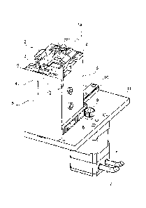
Fig. 1 shows a diagrammatic three-dimensional view of an exemplary embodiment
of the apparatus according to the invention. The drawing shows a first sub-
unit 6
with a transport device 1, wherein the transport device 1 in the present
embodiment
comprises, for example, transport rollers 1. Furthermore, the second sub-unit
5 is
shown, wherein in the present embodiment it is a vertical unit that is firmly
affixed to
a base plate 11. In contrast to this, in this exemplary embodiment the first
sub-unit 6
can move in a linear manner along the linear axis 10, which movement is
handled by
a mechanical drive 8. In this arrangement the relative movement need not be
carried
out on a linear axis as shown, but instead it can move along three-dimensional
curves
as desired.
CA 02713941 2014-03-11
- 28 -
According to a further exemplary embodiment of the present invention, the
cutting
implement is attached to the first sub-unit.
This exemplary embodiment of the apparatus according to the invention is, for
example, shown in Fig. 1, whose first sub-unit 6 comprises, for example, two
cutting tools 2. These are mechanical cutting implements with blades, wherein
the
above-mentioned more specialised cutting implements cannot be excluded as
possible cutting implements.
In an exemplary embodiment the movement can be implemented by means of
pneumatics with corresponding compressed-air supply lines 7. However, in
principle,
any electrical, hydraulic or mechanical drive to generate the relative
movement
between the first sub-unit and the second sub-unit is possible. In this
embodiment it
is thus the case that the second sub-unit 5 does not move, whereas the
relative
movement between the two sub-units is caused by the first sub-unit 6. In this
exemplary embodiment this first sub-unit is shown as a slide on the linear
axis. In
order to ensure that the semi-finished textile product is cut to length, in an
exemplary
manner two mechanical cutters 2 are shown that are in place on the first sub-
unit. If
the semi-finished textile product has been laid in a corresponding length by
means of
transport rollers 1, and if by means of the relative movement between the
first and
the second sub-units the future middle of the semi-finished textile product
has been
positioned to the middle of the gap within the uptake device 14, then the semi-
finished textile product can be cut to length. Only in this way is it possible
to affix
the individual pieces of the semi-finished textile product, in other words
individual
fibre bundles or individual rovings, individually and in a targeted manner at
positions
within the cellular material. The uptake device 3 with its gap 14 comprises a
channel
9 for the semi-finished textile product 4 so that the semi-finished product
can be
placed in through the uptake device by means of the transport rollers. As
shown in
Fig. 1, the end may protrude freely from the uptake device 3.
In the above arrangement it is particularly significant that the variant of
the transport
device, the variant of the cutting implement, the variant for generating the
relative
movement between the first and the second sub-units, as well as the variant
for
generating the relative movement between the uptake device and the hook are
selected as examples, and according to preceding paragraphs of the present
description are possible in other embodiments.
CA 02713941 2014-03-11
- 29 -
The relative movement 13 between the uptake device 3 and the hook can in this
case,
for example, be effected by the slide 12 for transverse movement of the uptake
device 3. This would correspond to a relative movement in which only the
uptake
device moves while the hook (not shown in the diagram) is at rest.
By means of the apparatus according to the invention shown in Fig. 1 the basic
idea
of the invention can be implemented. By means of the apparatus according to
the
invention a situation can thus be achieved in which improvement of the
mechanical
characteristics of cellular materials is implemented by the fibres, as
desired, rather
than being implemented by the incorporated resin as is the case in hitherto
known methods.
In order to be able to manufacture such an improved cellular material with the
apparatus according to the invention in an automated process, the following
individual steps are carried out by the apparatus according to the invention,
which
apparatus is shown in Fig. 1: lay the rovings at a defined length, cut the
rovings,
place the rovings in the middle into the needle and open the loop in the
needle at the
top. In process automation the individual functions, in the present embodiment
in
Fig. 1, are implemented as follows. The entire functional unit comprises two
sub-
units. The first sub-unit 6, shown as a slide, moves on the base plate 11 by
means of
a linear axis 10, wherein the second sub-unit 5, shown as a vertical unit, is
rigidly
installed on the base plate. In the first step the rollers I convey the roving
4 forward
to the desired length. In this process the textile product is threaded through
the
uptake device 3, while its other end can hang down freely. In the next step
the slide 6
moves along the linear axis by a distance required for the middle of the
roving to be
situated exactly in the middle of the gap of the uptake device 3. When the
roving is
positioned, the hooked needle penetrates the substrate and on the substrate
bottom
encounters the gap of the unit 3 or the uptake device 3. In order to thread
the roving
into the hook the uptake device 3 is arranged on a slide 12 which, for example
pneumatically driven, can make a sideways movement. When the hook is in the
gap,
CA 02713941 2014-03-11
- 30 -
the opening points to the side on which the roving was laid. In this context
the term
opening refers to an opening of the hook in order to make it possible at all
to place
the roving in the hook. For example, this hook can also be provided by opening
an
otherwise closed hook. If the small slide then makes a sideways movement
towards
the needle, then the roving is placed into the hook. Before the needle makes a
reverse
movement the roving is cut to length by means of the cutters or the cutting
implement 2.
According to an exemplary embodiment of the present invention, the apparatus
comprises at least one transport roller as a transport device.
In this arrangement these transport rollers make possible steady and
continuous
mechanical transport of the semi-finished textile product into the uptake
device.
The transport rollers are, for example, clearly shown in Fig. 1 and designated
by
the reference character 1. Furthermore, Figs 2a-f illustrate in a top view the
function and significance of the rollers for prewinding the semi-finished
textile
product or the roving. In order to provide the semi-finished textile product
that at
a later stage can be inserted as reinforcement in the cellular material at a
suitable
length and in the middle at the position of uptake by the hook, the rollers
handle
prewinding of the semi-finished product. In combination with positioning the
middle of the gap relative to the middle of the part of the semi-finished
product,
which part is located within the apparatus according to the invention,
prewinding
of the roving or of the semi-finished product makes it possible to provide the
semi-finished textile product at a predefined length at the location at which
said
semi-finished textile product is at a later stage taken up by a hook. In this
context
the term "the part of the semi-finished product ,which part is located within
the
apparatus according to the invention" refers to that part of the semi-finished
product which, for example, in Fig. 2c is situated to the left-hand side of
the
cutting implement. This starting point for measuring the length of the semi-
finished product within the apparatus according to the invention is selected
because in some exemplary embodiments the length of the semi-finished product
to be processed is determined by the cutters during a cutting process.
CA 02713941 2014-03-11
- 30a -
In order to implement a single-face sewing method in which generating the
through-holes in the material is not carried out at the same time with the
feed-
through of the reinforcing material, in other words with the pins, the above
method-related steps according to the invention are stated. In this
arrangement
Figs 2a to f describe that part of the method that happens on the bottom face
of the
material to be reinforced. The diagrams thus show the semi-finished textile
product during prewinding of a roving, as well as positioning of the middle of
the
semi-finished product to the location of the subsequent uptake. Insertion of
the
hook into the material to be reinforced can, for example, be accomplished by
the
top partial system according to the invention and is, for example, carried out
with
a special sewing device that is intended for pulling fibre bundles into a
cellular
material. Placing the semi-finished product in the hook can, for example, be
implemented by a relative movement of the hook relative to the semi-finished
textile product. In order to lay the semi-finished textile product up in the
material
to be reinforced the hook is withdrawn through the material, wherein
subsequently
the semi-finished textile product or the fibre bundle is released from the
hook. In
this process the initial situation of the method is reached, wherein the term
"initial
situation" in this context does not relate to the state of the already
processed
material, but instead describes the state and the situation of the apparatus
that
implements the method. After this initial situation has been reached, the
method
can thus be started and implemented anew and in the initial state of the
apparatus.
The following Figs 2a to f show various states of the apparatus according to
the
invention during implementation of the method according to the invention for
manufacturing a reinforced cellular material and for taking up a semi-finished
textile
product in a hook.
Fig. 9A shows a diagrammatic two-dimensional view of an exemplary embodiment
of
the apparatus according to the invention. In this arrangement the apparatus is
shown
in top view. The transport device is shown in an exemplary manner as transport
rollers 1, which moves the semi-finished textile product 4 into the channel
for the
CA 02713941 2014-03-11
- 30b
semi-finished textile product 9 within the uptake device 3. The gap within the
uptake
device 14 later ensures the volume region in which the hooked needle can take
up the
roving or the semi-finished product. In this arrangement Fig. 2a shows the
initial
situation of the method according to the invention by means of the apparatus
according to the invention. In this arrangement the arrow 17 shows the
direction of
the relative movement of the first sub-unit relative to the second sub-unit,
wherein in
the present embodiment the cutters 2 in an exemplary manner are designed as a
mechanical cutting implement.
Fig. 2b shows the state of the apparatus according to the invention in the
implementation of the method according to the invention, wherein in this
process
step prewinding of the semi-finished textile product by means of the transport
rollers
1 is shown. The diagram clearly shows the semi-finished textile product 14a in
the
CA 02713941 2014-03-11
- 31 -
gap of the uptake device. By prewinding the semi-finished product the channel
9 for
the semi-finished textile product in the uptake device 3 is full, and the end
of the
semi-finished textile product 4 hangs down freely on the left-hand side of the
figure.
Fig. 2c shows a two-dimensional diagrammatic view of the apparatus according
to
the invention during the process step in which the relative movement between
the
first sub-unit and the second sub-unit has moved to such an extent that the
middle of
the semi-finished product is situated exactly in the middle of the gap of the
uptake
device 14.1n a subsequent step, the middle of the gap 18 will be the location
at
which the hook takes up the semi-finished textile product. In this arrangement
the
arrow 17 indicates the direction of the relative movement of the first sub-
unit relative
to the second sub-unit. This involves, or at least does not preclude, the
possibility of
all three options of the movement type, namely movement of the first and the
second
sub-units; movement of the first sub-unit only; or movement of the second sub-
unit
only.
The term middle of the semi-finished textile product is illustrated in Fig.
2c. Thus
the middle of the semi-finished textile product is measured from the position
at
which the semi-finished textile product will at a later stage actually- or
possibly,
depending on requirements, be cut by the cutters or the cutting implement. The
part of the semi-finished textile product, which part in Fig. 2c is to the
left-hand
side of the cutters, is equal to the entire length of the part of the semi-
finished
product, which part is subsequently in a further step taken up and placed in
the
material to be reinforced. The relative movement of the first sub-unit
relative to
the second sub-unit is then completed such that the distance from the possible
cutting implements 2 to the middle of the gap of the uptake device is
precisely
equal in length to the distance from the middle of the gap to the end of the
semi-
finished textile product.
CA 02713941 2014-03-11
= - 3 1 a -
Fig. 2c clearly shows that that part of the semi-finished textile product that
is situated
on the left-hand side of the cutters or of the cutting implement 2 has been
positioned
by the relative movement precisely such that the middle of the semi-finished
product
4 coincides precisely with the middle of the gap 14a or 18. This ensures that
after
uptake of the semi-finished product by the hook, even distribution of the
textile
material within the cellular material is ensured.
Fig. 2d shows a diagrammatic two-dimensional view of the apparatus according
to
the invention in the implementation of the method according to the invention.
Fig. 2d
shows the step of inserting the needle 15 that comprises a corresponding hook
16.
The left-hand region of the drawing 2d shows a top view of the apparatus
according
to the invention with the transport rollers 1 and the semi-finished product 4
as well as
the cutters 2. On the right-hand side of Fig. 2d there is a magnified view of
that area
in which the gap of the uptake device 3 is located. This right-hand region of
Fig. 2d
=
CA 02713941 2010-05-20
- 32 -
shows this gap including the needle with the hook 15 and 16 as well as the
uptake
device 3b in cross section. Likewise, the right-hand part of the figure shows
the
semi-finished textile product in cross section 4a. In this situation, in which
the needle
has made a hole through the cellular material situated above it, and for the
purpose of
uptake has entered the gap of the uptake device, the needle 15 with the hook
16 is
still some distance away from the textile fibre. It is only as a result of a
subsequent
relative movement that the fibre can be placed in the needle 15.
Just like the previous Fig. 2d, Fig. 2e shows a top view of the apparatus
according to
the invention on the left-hand side, and the cross section of the gap of the
uptake
device 3 on the right-hand side. In this arrangement the left-hand side shows
that as a
result of the relative movement of the uptake device 3 relative to the hook or
the
hooked needle 15, indicated by the arrow 3, placement of the textile in the
needle or
in the hook can take place. In this arrangement the uptake device is shown in
cross
section 3b; said uptake device quasi serves as a resistance in the placement
of the
semi-finished product 4b. Due to the contact pressure, which results from the
uptake
device 3 that in the present diagram is shown in cross section, the semi-
finished
textile material is pressed into the opening of the needle 15. In this context
it is also
of decisive importance that the relative movement allows all three options of
movement of the uptake device and of the hook. Once the semi-finished product
has
been placed in the hook, then by means of the cutters 2 the roving or the semi-
finished textile product can be cut to length. Thereafter the needle can make
a reverse
movement and place the roving or the semi-finished textile product into the
cellular
material to be reinforced. At the top (not shown in the diagram) of the
material,
release b or undoing of the loop takes place, which loop has formed from the
reinforcement material around the hook.
Fig. 2f shows a diagrammatic two-dimensional top view of the apparatus
according
to the invention. In this arrangement the two arrows indicate the
corresponding
counter movements to the previously made relative movements in order to reach
the
CA 02713941 2010-05-20
- 33 -
initial situation after withdrawal of the needle. Thereafter, the first step,
according to
the invention, of the method can be repeated after the position of the
material to be
reinforced has been changed.
Fig. 3 shows a diagrammatic three-dimensional view of the method according to
the
invention according to the apparatus according to the invention or the system
according to the invention. In this arrangement, in seven successive images,
individual steps are shown, viewed from the top of the cellular material. The
needle
is shown, which is still at the top of the cellular material. The cellular
material 19
10 is rectangular in shape and is to be reinforced with a semi-finished
textile product at
predetermined locations. Sub-figure 4 shows that after insertion of the needle
15 in
the cellular material 19 during withdrawal of the needle within the previously
generated hole a hooked-in semi-finished textile product, having been fed
through
the cellular material, exits at the top of the cellular material. The
subsequent sub-
15 figure 5 shows a pair of scissors for manually cutting the semi-finished
textile
product detaching the semi-finished textile product from the hooked needle 15.
The
next sub-figure 6 shows various fed-through pieces of semi-finished textile
product,
wherein these pieces have been placed through the cellular material in three
parallel
rows. The next and last sub-figure 7 shows an enlargement of the cellular
material 19
in which the complete cellular material comprises regularly reinforced
positions after
all the pieces of semi-finished textile product have been worked in.
Fig. 4 shows a diagrammatic two-dimensional view of the system according to
the
invention for the production of reinforced materials. The diagram shows a top
partial
system 24 and a bottom partial system 25, and between them a middle unit 27
for
supporting the material to be processed. In order to be able to position this
material
to be processed as far as the insertion point, which is defined by the upper
unit 24, is
concerned, a transport mechanism 28 for the middle unit is provided. In this
arrangement a computer unit 26 is in a position to control the transport
mechanism of
the middle unit. Furthermore, the upper and the lower units or the top and the
bottom
CA 02713941 2014-03-11
- 34 -
partial systems are completely automatically controllable by lines from the
computer
unit to the respective units to be controlled. In this arrangement the upper
partial
system can comprise a needle bar drive, while the bottom partial system can be
apparatus according to the apparatus according to the invention. By means of
the
system shown in Fig. 4 it is thus possible to manufacture reinforced cellular
materials
completely automatically, wherein even locally varying pin densities can be
implemented by the system according to the invention.
Figs 5a and 5b show two needles of different designs by means of which needles
the
method according to the invention can be implemented in an exemplary manner,
or
which needles can be used for utilising the apparatus according to the
invention. Fig.
5a shows a first embodiment of a hooked needle 30 that comprises a straight-
line
shaft 31 whose front tapers to form a point 32. In the region of the point 32
the
needle 30 comprises an eyelet 33, which, however, comprises an opening on one
side
so that through it a fibre bundle can be inserted in the eyelet region of the
needle 30.
The hooked needle 30 shown in Fig. 5b substantially corresponds to that shown
in Fig.
5a, except that in addition to the hooked needle 30 shown in Fig. 5a it
comprises a
closure mechanism 35 that is designed to close the opening of the eyelet 33
during
pulling-out of the hooked needle 30 from a cellular material. The closure
mechanism
35 comprises a flap 36 that in its initial position comes to rest in a tapered
region 37 at the shaft of the needle 30. As soon as the free end of this flap
36 during
the pulling-out of the needle from the cellular material contacts said
cellular material,
said flap 36 moves clockwise from its initial position to a position in which
it
completely closes the opening of the eyelet 33, as shown in Fig. 5b. This
avoids a
situation in which when the needle 30 is withdrawn from the cellular material
the
hook end of the second limb damages the interior wall of a through-hole in the
cellular material. Furthermore, the closure mechanism 35 ensures that no
fibres
become detached from the fibre bundle during pulling-in into the cellular
material. If
the cellular material, including already applied cover layers, is perforated,
the closure
6 .6 = 6 = 0 = == = ,= =
e = 6.6
CA 02713941 2010-05-20
- 35 -
mechanism 35 prevents a situation in which, on the way back, fibres from the
textiles
are gripped by the needle 30 and are pulled into the interior of the hole.
Fig. 6 shows a diagrammatic three-dimensional view of a system 600 according
to
the invention, with a top partial system 602 and a bottom partial system 603.
In this
arrangement the needle 601, which after penetration into the material to be
reinforced
takes up the semi-finished textile product in the bottom partial system 603,
is affixed
to the rod 607. This rod forms part of the needle bar drive 604. Furthermore,
supply
lines for the drive of the lower partial system 605 are shown. The region
between the
top and the bottom partial system, into which region the material for
reinforcement is
incorporated, is designated 606.
. õ =
CA 02713941 2010-05-20
- 36 -
List of reference characters
1 Transport rollers
2 Cutters
3 Uptake device
3a Uptake device in positioning location
3b Cross section of uptake device 3
4 Semi-finished textile product
4a Cross section of semi-finished textile product
4b Placed semi-finished textile product
5 Second sub-unit
6 First sub-unit
7 Connections for the control system
8 Drive mechanism
9 Channel for the semi-finished textile product
10 Linear axis
11 Base plate
12 Slide for transverse movement of the uptake device 3
13 Direction of relative movement of the uptake device relative to the
hook
14 Gap in the uptake device 3
14a Gap in the uptake device 3 with semi-finished textile product
15 Needle
16 Hook on the needle
17 Direction of the relative movement of the first sub-unit relative to
the second
sub-unit
18 Middle of the gap 14
19 Cellular material
20 Chopped semi-finished textile product after being fed through the
cellular
material
21 Scissors for manual cutting of the semi-finished textile product
-
CA 02713941 2010-05-20
- 37 -
22 Fed-through pieces of semi-finished textile product in rows
23 Complete cellular material after all the pieces of the semi-finished
textile
product have been worked in
24 Top partial system
25 Bottom partial system
26 Computer unit
27 Middle unit for supporting the material to be processed
28 Transport mechanism of the middle unit
29 Lines for controlling the various units by the computer unit
30 Hooked needle
31 Shaft
32 Tip
33 Eyelet
34 First limb
35 Closure mechanism
36 Flap
37 Tapered region
600 System with top and bottom partial system
601 Needle
602 Top partial system
603 Bottom partial system
604 Needle bar drive
605 Supply lines for bottom drive
606 Region for placing the material to be reinforced
607 Bar of the needle bar drive