Note: Descriptions are shown in the official language in which they were submitted.
CA 02714768 2010-08-13
WO 2009/101424 PCT/GB2009/000414
1
Flow stop valve
This disclosure relates to a flow stop valve which may be positioned in a
downhole
tubular, and particularly relates to a flow stop valve for use in dual density
drilling fluid
systems.
Background
When drilling a well bore, it is desirable for the pressure of the drilling
fluid in the newly
drilled well bore, where there is no casing, to be greater than the local pore
pressure of
the formation to avoid flow from, or collapse of, the well wall. Similarly,
the pressure of
the drilling fluid should be less than the fracture pressure of the well to
avoid well
fracture or excessive loss of drilling fluid into the formation. In
conventional onshore (or
shallow offshore) drilling applications, the density of the drilling fluid is
selected to
ensure that the pressure of the drilling fluid is between the local formation
pore
pressure and the fracture pressure limits over a wide range of depths. (The
pressure
of the drilling fluid largely comprises the hydrostatic pressure of the well
bore fluid with
an additional component due to the pumping and resultant flow of the fluid.)
However,
in deep sea drilling applications the pressure of the formation at the seabed
SB is
substantially the same as the hydrostatic pressure HP of the sea at the seabed
and the
subsequent rate of pressure increase with depth d is different from that in
the sea, as
shown in figure la (in which P represents pressure and FM and FC denote
formation
pressure and fracture pressure respectively). This change in pressure gradient
makes
it difficult to ensure.that the pressure of the drilling fluid is between the
formation and
fracture pressures over a range of depths, because a single density SD
drilling fluid
does not exhibit this same step change in the pressure gradient.
To overcome this difficulty, shorter sections of a well are currently drilled
before the
well wall is secured with a casing. Once a casing section is in place, the
density of the
drilling fluid may be altered to better suit the pore pressure of the next
formation section
to be drilled. This process is continued until the desired depth is reached.
However,
the depths of successive sections are severely limited by the different
pressure
gradients, as shown by the single density SD curve in figure 1 a, and the time
and cost
to drill to a certain depth are significantly increased.
CA 02714768 2010-08-13
WO 2009/101424 PCT/GB2009/000414
2
In view of these difficulties, dual density DD drilling fluid systems have
been proposed
(see US2006/0070772 and W02004/033845 for example). Typically, in these
proposed systems, the density of the drilling fluid returning from the
wellbore is
adjusted at or near the seabed to approximately match the density of the
seawater.
This is achieved by pumping to the seabed a second fluid with a different
density and
mixing this fluid with the drilling fluid returning to the surface. Figure lb
shows an
example of such a system in which a first density fluid 1 is pumped down a
tubular 6
and through a drilling head 8. The first density fluid 1 and any cuttings from
the drilling
process then flow between the well wall and the tubular. Once this fluid
reaches the
seabed, it is mixed with a second density fluid 2, which is pumped from the
surface SF
via pipe 10. This mixing process results in a third density fluid 3, which
flows to the
surface within a riser 4, but is also outside the tubular 6. The fluids and
any drilling
cuttings are then separated at the surface and the first and second density
fluids are
reformed for use in the process.
In alternative proposed systems, a single mixture is pumped down the tubular
and
when returning to the surface the mixture is separated into its constituent
parts at the
seabed. These separate components are then returned to the surface via the
riser 4
and pipe 10, where the mixture is reformed for use in the process.
With either of the dual density arrangements, the density of the drilling
fluid below the
seabed is substantially at the same density as the fluid within the tubular
and the
density of the first and second density fluids may be selected so that the
pressure of
the drilling fluid outside the tubular and within the exposed well bore is
between the
formation and fracture pressures.
Such systems are desirable because they recreate the step change in the
hydrostatic
pressure gradient so that the pressure gradient of the drilling fluid below
the seabed
may more closely follow the formation and fracture pressures over a wider
range of
depths (as shown by the dual density DD curve in figure 1a). Therefore, with a
dual
density system, greater depths may be drilled before having to case the
exposed well
bore or adjust the density of the driiiing fluid and significai t savings may
be made.
Furthermore, dual density systems potentially allow deeper depths to be
reached and
hence greater reserves may be exploited.
CA 02714768 2010-08-13
WO 2009/101424 PCT/GB2009/000414
3
However, one problem with the proposed dual density systems is that when the
flow of
drilling fluid stops, there is an inherent hydrostatic pressure imbalance
between the
fluid in the tubular and the fluid outside the tubular, because the fluid
within the tubular
is a single density fluid which has a different hydrostatic head to the dual
density fluid
outside the tubular. There is therefore a tendency for the denser drilling
fluid in the
tubular to redress this imbalance by displacing the less dense fluid outside
the tubular,
in the same manner as a U-tube manometer. The same problem also applies when
lowering casing sections into the well bore.
Despite there being a long felt need for dual density drilling, the above-
mentioned
problem has to-date prevented the successful exploitation of dual density
systems and
the present disclosure aims to address this issue, and to reduce greatly the
cost of dual
density drilling.
Statements of Invention
According to one embodiment of the invention, there is provided a flow stop
valve
positioned in a downhole tubular, wherein: the flow stop valve is in a closed
position
when a pressure difference between fluid outside the downhole tubular and
inside the
downhole tubular immediately above or at the flow stop valve is below a
threshold
value, thereby preventing flow through the downhole tubular; and the flow stop
valve is
in an open position when the pressure difference between fluid outside the
downhole
tubular and inside the downhole tubular immediately above or at the flow stop
valve is
above a threshold value, thereby permitting flow through the downhole tubular.
The threshold value for the pressure difference between fluid outside the
tubular and
inside the downhole tubular at the flow stop valve may be variable.
The flow stop valve may comprise: a first biasing element; and a valve;
wherein the first
biasing element may act on the valve such that the first biasing element may
bias the
valve towards the closed position; and wherein the pressure difference between
fluid
outside the down hole tubular and inside the tubular may also act on the valve
and may
bias the valve towards an open position, such that when the pressure
difference
exceeds the threshold value the valve may be in the open position and drilling
fluid may
be permitted to flow through the downhole tubular. The first biasing element
may
comprise a spring.
CA 02714768 2010-08-13
WO 2009/101424 PCT/GB2009/000414
4
The flow stop valve may further comprise a housing, and a hollow tubular
section and a
sleeve located within the housing, the sleeve may be provided around the
hollow
tubular section and the sleeve may be located within the housing, the housing
may
comprise first and second ends and the hollow tubular section may comprise
first and
second ends, the first end of the hollow tubular section corresponding to the
first end of
the housing, and the second end of the hollow tubular section corresponding to
a
second end of the housing.
The hollow tubular section may be slidably engaged within the housing. The
sleeve
may be slidably engaged about the hollow tubular section.
The hollow tubular section may comprise a port such that the port may be
selectively
blocked by movement of the hollow tubular section or sleeve, the port may form
the
valve such that in an open position a flow path may exist from a first end of
the
housing, through the port and the centre of the tubular section to a second
end of the
housing.
A third abutment surface may be provided at a first end of the hollow tubular
section
such that the third abutment surface may limit the travel of the sleeve in the
direction
toward the first end of the housing. A flange may be provided at the second
end of the
hollow tubular section. A second abutment surface may be provided at the
second end
of the housing such that the second abutment surface of the housing may abut
the
flange of the tubular section limiting the travel of the hollow tubular
section in a second
direction, the second direction being in a direction towards the second end of
the
housing.
A first abutment surface may be provided within the housing between the second
abutment surface of the housing and the first end of the housing, such that
the first
abutment surface may abut the flange of the hollow tubular section limiting
the travel of
the hollow tubular section in a first direction, the first direction being in
a direction
towards the first end of the housing.
A spacer element of variable dimensions may be provided between the second
abutment surface of the housing and the flange of the hollow tubular section,
such that
CA 02714768 2010-08-13
WO 2009/101424 PCT/GB2009/000414
the limit on the travel of the hollow tubular section in the second direction
may be
varied.
A second biasing element may be provided between the second abutment surface
of
5 the housing and the flange of the hollow tubular section. The second biasing
element
may comprise a spring.
The first biasing element may be provided about the hollow tubular section and
the first
biasing element may be positioned between the first abutment surface of the
housing
and the sleeve such that it may resist movement of the sleeve in the second
direction.
A piston head may be provided at the first end of the hollow tubular section.
Fluid
pressure at the first end of the housing may act on the piston head and an end
of the
sleeve facing the first end of the housing. The projected area of the piston
head
exposed to the fluid at the first end of the housing may be greater than the
projected
area of the sleeve exposed to the fluid at the first end of the housing.
The sleeve, housing, hollow tubular section and first abutment surface may
define a
first chamber, such that when the valve is closed, the first chamber may not
be in flow
communication with the second end of the housing. A passage may be provided
through the sleeve, the passage may provide a flow path from the first end of
the
housing to the first chamber. The projected area of the sleeve facing the
fluid in the
first end of the housing is greater than the projected area of the sleeve
facing the fluid
in the first chamber.
A second chamber may be provided between the sleeve and the housing, the
chamber
may be sealed from flow communication with the first end of the housing and
the first
chamber. A fourth abutment surface may be provided on an outer surface of the
sleeve and a fifth abutment surface may be provided within the housing, such
that the
fourth and fifth abutment surfaces may define the second chamber and limit the
movement of the sleeve in the direction toward the second end of the housing.
A vent may be provided in the housing wall, the vent may provide a flow path
between
the second chamber and outside the housing of the flow stop valve. The surface
of the
sleeve defined by the difference between: the projected area of the sleeve
facing the
CA 02714768 2010-08-13
WO 2009/101424 PCT/GB2009/000414
6
fluid in the first end of the housing; and the projected area of the sleeve
facing the fluid
in the first chamber, may be exposed to the fluid outside the flow stop valve.
A pressure difference between fluid on a first side of the valve and on a
second side of
the valve may be substantially the same as the pressure difference between
fluid
outside the downhole tubular and inside the downhole tubular immediately above
the
flow stop valve.
The flow stop valve may comprise: a third biasing element; and a valve;
wherein the
third biasing element may act on the valve such that the third biasing element
may bias
the valve towards the closed position; and wherein the pressure difference
between
fluid on a first side of the valve and on a second side of the valve may also
act on the
valve and bias the valve towards an open position, such that when the pressure
difference exceeds the threshold value the valve may be in the open position
and
drilling fluid is permitted to flow through the downhole tubular.
The flow stop valve may further comprise a housing, and a spindle, the spindle
may be
located within the housing, and may be slidably received in a first receiving
portion at a
first end of the housing and a second receiving portion at a second end of the
housing,
the housing may comprise a first abutment surface and the spindle may comprise
a
second abutment surface, such that the valve may be in a closed position when
the
second abutment surface of the spindle engages the first abutment surface of
the
housing.
The spindle may comprise first and second ends, the first end of the spindle
corresponding to the first end of the housing, and the second end of the
spindle
corresponding to a second end of the housing.
The first end of the spindle and the first receiving portion may define a
first chamber
and the second end of the spindle and the second receiving portion may define
a
second chamber, the first and second chambers may not be in flow communication
with first and second ends of the housing respectively. Tile third biasll g
element may
lay
comprise a spring provided in the first chamber.
There may be provided a first passage through the spindle from the first end
of housing
to the second chamber and a second passage through the spindle from the second
CA 02714768 2010-08-13
WO 2009/101424 PCT/GB2009/000414
7
end of the housing to the first chamber, such that the first chamber may be in
flow
communication with the second end of the housing and the second chamber may be
in
flow communication with the first end of the housing.
There may be provided a first passage through the spindle from the first end
of housing
to the second chamber and a second passage from a hole in a side wall of the
housing
to the first chamber, such that the first chamber may be in flow communication
with
fluid outside the downhole tubular and the second chamber may be in flow
communication with the first end of the housing.
The projected area of the first end of the spindle facing the fluid in the
first chamber
may be less than the projected area of the second end of the spindle facing
the fluid in
the second chamber.
One or more of the spindle, the first receiving portion and the second
receiving portion
may be manufactured from drillable materials. One or more of the spindle, the
first
receiving portion and the second receiving portion may be manufactured from a
selection of materials including brass and aluminium.
The flow stop valve may be for use in, for example, drilling and cementing and
may be
used to control the flow of completion fluids in completion operations. The
flow stop
valve may be for use in offshore deep sea applications. In such applications,
the
downhole tubular may extend, at least partially, from the surface to a seabed.
The
downhole tubular may be, at least partially, located within a riser, the riser
extending
from the seabed to the surface. The threshold value may be greater than or
equal to
the pressure difference between the fluid outside the tubular and inside the
downhole
tubular at the seabed. The first end of the housing may be located above the
second
end of the housing, the first end of the housing may be connected to a
drillstring or
casing section and the second end of the housing may be connected to another
drillstring or casing section or a drilling device.
The fluid in the downhole tubular may be at a first density. A fluid at a
second density
may be combined at the seabed with fluid returning to the surface, so that the
resulting
mixture between the riser and downhole tubular may be at a third density.
CA 02714768 2010-08-13
WO 2009/101424 PCT/GB2009/000414
8
According to another embodiment, there is provided a method for preventing
flow in a
downhole tubular, wherein when a difference between the pressure of fluid
outside the
downhole tubular and the pressure of fluid inside the downhole tubular at a
flow stop
valve is below a threshold value, the flow stop valve is in a closed position,
preventing
flow through the downhole tubular, and when a difference between the pressure
of fluid
outside the downhole tubular and the pressure of fluid inside the downhole
tubular at
the flow stop valve is above a threshold value, the flow stop valve is in an
open
position, permitting flow through the downhole tubular.
According to another embodiment, there is provided a method for preventing
flow in a
downhole tubular, wherein when a difference between the pressure of fluid on a
first
side of a flow stop valve and the pressure of fluid on a second side of the
flow stop
valve is below a threshold value, the flow stop valve is in a closed position,
preventing
flow through the downhole tubular, and when a difference between the pressure
of fluid
on a first side of the flow stop valve and the pressure of fluid on a second
side of the
flow stop valve is above a threshold value, the flow stop valve is in an open
position,
permitting flow through the downhole tubular.
The method may comprise drilling in a dual fluid density system with the flow
stop valve
disposed in a drill string. The method may comprise cementing in a dual fluid
density
system with the flow stop valve disposed adjacent to a casing section. The
flow stop
valve may be provided in a shoe of a casing string.
According to another embodiment, there is provided a method for drilling in a
dual fluid
density system using a valve, the valve preventing flow in a downhole tubular,
wherein
when a difference between the pressure of fluid outside the downhole tubular
and the
pressure of fluid inside the downhole tubular at a flow stop valve is below a
threshold
value, the flow stop valve is in a closed position, preventing flow through
the downhole
tubular, and when a difference between the pressure of fluid outside the
downhole
tubular and the pressure of fluid inside the downhole tubular at the flow stop
valve is
above a threshold value, the flow stop valve is in an open position,
permitting flow
through the dorrnhol~ . tubular.
According to a further embodiment, there is provided a method for drilling in
a dual fluid
density system using a valve, the valve preventing flow in a downhole tubular,
wherein
when a difference between the pressure of fluid on a first side of a flow stop
valve and
CA 02714768 2010-08-13
WO 2009/101424 PCT/GB2009/000414
9
the pressure of fluid on a second side of the flow stop valve is below a
threshold value,
the flow stop valve is in a closed position, preventing flow through the
downhole
tubular, and when a difference between the pressure of fluid on a first side
of the flow
stop valve and the pressure of fluid on a second side of the flow stop valve
is above a
threshold value, the flow stop valve is in an open position, permitting flow
through the
downhole tubular.
Brief Description of the Drawings
For a better understanding of the present disclosure, and to show more clearly
how it
may be carried into effect, reference will now be made, by way of example, to
the
following drawings, in which:
Figure la is a graph showing the variation of a formation and fracture
pressures
beneath the seabed;
Figure 1 b is a schematic diagram showing a proposed arrangement for one
embodiment of a dual density drilling system;
Figure 1c is a schematic diagram showing the positional arrangement of the
flow stop
valve according to a first embodiment of the disclosure;
Figure 2 is a sectional side-view of the flow stop valve according to a first
embodiment
of the disclosure;
Figures 3a and 3b are sectional side-views showing the valve sleeve according
to a
first embodiment of the disclosure with figure 3b being an enlarged view of
figure 3a;
Figures 4a, 4b and 4c are sectional side-views of the flow stop valve in the
closed, pre-
loaded and open positions according to a first embodiment of the disclosure;
Figures 5a, 5b, 5c, 5d, 5e and .5f ale sectional side-views of the flow stop
valve
according to a second embodiment of the disclosure.
Figure 6 is a sectional side-view of the flow stop valve according to a third
embodiment
of the disclosure;
CA 02714768 2010-08-13
WO 2009/101424 PCT/GB2009/000414
Figure 7 is a sectional side-view of the flow stop valve according to a fourth
embodiment of the disclosure; and
5 Figure 8 is a sectional side view of the flow stop valve according to a
fifth embodiment
of the disclosure.
Detailed Description
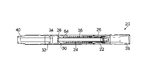
10 With reference to figure 1c, a flow stop valve 20, according to a first
embodiment of the
disclosure, is located in a tubular 6 (e.g., a drillstring or casing string)
such that, when a
drilling head 8 is in position for drilling, the flow stop valve 20 is at any
desired point in
the tubular, for example, between the seabed SB and the drilling head 8. The
illustrated flow stop valve 20 ensures that before the flow of drilling fluid
1 is started, or
when it is stopped, the drilling fluid within the tubular 6 is restricted from
flow
communication with the fluid 1, 3 outside the tubular, thereby preventing
uncontrollable
flow due to the hydrostatic pressure difference described above.
With reference to Figure 2, the flow stop valve 20, according to the first
embodiment of
the disclosure, comprises a tubular housing 22 within which there is disposed
a hollow
tubular section 24. The housing 22 comprises a box 38 at a first end of the
housing
and a pin 40 at a second end of the housing. (NB, the first end of a component
will
hereafter refer to the rightmost end as shown in figures 2-4 and accordingly
the second
end will refer to the leftmost end.) The box 38 and pin 40 allow engagement of
the flow
stop valve 20 with adjacent sections of a tubular and may comprise
conventional box
and pin threaded connections, respectively. Although the terms "box" and "pin"
are
used, any connection to a tubular could be used, for example a socket and plug
arrangement. Alternatively, the flow stop valve 20 could be unitary with the
tubular 6.
A sleeve 26 is slidably disposed within the housing 22 about a first end of
the hollow
tubular section 24, such that the sleeve 26 may slide along the hollow tubular
section
24 at its first end, and the sleeve 26 may also slide within the housing 22. A
flange 28
is provided at a second end of the hollow tubular section 24 and a first
abutment
shoulder 30 is provided within the housing 22 between the first and second
ends of the
hollow tubular section 24 such that the hollow tubular section 24 is slidably
engaged
within the innermost portion of the first abutment shoulder 30 and the motion
of the
CA 02714768 2010-08-13
WO 2009/101424 PCT/GB2009/000414
11
hollow tubular section 24 in a first direction towards the first end of the
housing is
limited by the abutment of the flange 28 against the first abutment shoulder
30. (NB,
the first direction is hereafter a direction towards the rightmost end shown
in figures 2-4
and accordingly the second direction is towards the leftmost end.) A second
abutment
shoulder 32 is provided within the housing 22 and is placed opposite the first
abutment
shoulder 30, so that the flange 28 is between the first and second abutment
shoulders
30, 32. Furthermore, a variable width spacer element 34 may be placed between
the
second abutment shoulder 32 and the flange 28 and motion of the hollow tubular
section 24 in a second direction towards the second end of the housing may be
limited
by the abutment of the flange 28 against the spacer element 34 and the
abutment of
the spacer element 34 against the second abutment shoulder 32. The flange 28
and
spacer element 34 may both have central openings so that the flow of fluid is
permitted
from the centre of the hollow tubular section 24 to the second end of the flow
stop valve
20.
The flow stop valve 20, according to the first embodiment of the disclosure,
may also
be provided with a spring 36, which is located between the first abutment
shoulder 30
and the sleeve 26. The illustrated spring 36 may resist motion of the sleeve
26 in the
second direction.
With reference to figures 3a and 3b, the hollow tubular section 24, according
to the first
embodiment of the disclosure, further comprises a cone shaped piston head 44
disposed at the first end of the hollow tubular section 24. The piston head 44
may be
provided with a third abutment shoulder 42, which abuts a first end of the
sleeve 26
thereby limiting motion of the sleeve 26 relative to the hollow tubular
section 24 in the
first direction. The piston head 44 may be any desired shape. For example, it
may be
cone shaped as in the illustrated embodiment. The hollow tubular section 24
may
further comprise one or more ports 46, which may be provided in a side-wall of
the
hollow tubular section 24 at the first end of the hollow tubular section 24.
The ports 46
may permit flow from the first end of the flow stop valve 20 into the centre
of the hollow
tubular section 24, through the openings in the flange 28 and spacer element
34 and
subsequently ly Fto the th. second end .l oil the nvW of t uhe flow valve
GnVn. ( 7lV-..W.eV@I the w stop VdI, VVl lell th Sleeve
26 abuts the third abutment shoulder 42 of the piston head 44, the sleeve 26
may block
the ports 46 and hence prevents flow from the first end of the flow stop valve
20 to the
centre of the hollow tubular section 24.
CA 02714768 2010-08-13
WO 2009/101424 PCT/GB2009/000414
12
The sleeve 26 may further comprise a sleeve vent 48 which provides a flow
passage
from the first end of the sleeve 26 to the second end of the sleeve 26 and
thence to a
first chamber 52, which contains the spring 36 and is defined. by the housing
22, the
hollow tubular section 24, the first abutment shoulder 30 and the second end
of the
sleeve 26. The sleeve vent 48 may thus ensure that the pressures acting on the
first
and second ends of the sleeve 26 are equal. However, the projected area of the
first
end of the sleeve 26 may be greater than the projected area of the second end
of the
sleeve 26 so that the force due to the pressure acting on the first end of the
sleeve 26
is greater than the force due to the pressure acting on the second end of the
sleeve 26.
This area difference may be achieved by virtue of a fourth abutment shoulder
54 in the
sleeve 26 and a corresponding fifth abutment shoulder 56 in the housing 22.
The
fourth abutment shoulder 54 may be arranged so that the diameter of the sleeve
26 at
its first end is greater than that at its second end and furthermore, motion
of the sleeve
26 in the second direction may be limited when the fourth and fifth abutment
shoulders
54, 56 abut. The fourth and fifth abutment shoulders 54, 56, together with the
sleeve
26 and housing 22 may define a second chamber 58 and a housing vent 50 may be
provided in the side-wall of the housing 22 so that the second chamber 58 may
be in
flow communication with the fluid outside the flow stop valve 20. The net
force acting
on the sleeve 26 is therefore the product of (1) the difference between the
pressure
outside the flow stop valve 20 and at the first end of the flow stop valve 20,
and (2) the
area difference between the first and second ends of the sleeve.
Seals 60, 62 may be provided at the first and second ends of the sleeve 26
respectively so that the second chamber 58 may be sealed from the first end of
the
flow stop valve 20 and the first chamber 52 respectively. Furthermore, seals
64 may
be provided on the innermost portion of the first abutment shoulder 30 so that
the first
chamber 52 may be sealed from the second end of the flow stop valve 20.
With reference to Figure 4a, 4b and 4c, operation of the flow stop valve 20,
according
to the first embodiment of the disclosure, will now be explained. The flow
stop valve 20
may be located in a tubular with the first end above the second end and the
flow stop
valve 20 may be connected to adjacent tubular sections via the box 30 and pin
40.
Prior to lowering of the tubular into the wellbore (e.g., the riser of an
offshore drilling
rig), there may be a small preload in the spring 36 so that the sleeve 26
abuts the third
abutment shoulder 42 of the piston head 44 and the ports 46 are closed, as
shown in
Figure 4a. In this position no drilling fluid may pass through the flow stop
valve 20.
CA 02714768 2010-08-13
WO 2009/101424 PCT/GB2009/000414
13
As the tubular and hence flow stop valve 20 is lowered into the riser, the
hydrostatic
pressures inside and outside the tubular and flow stop valve 20 begin to rise.
With one
embodiment of a dual density drilling fluid system, the density of the fluid
within the
tubular may be higher than the density of the fluid outside the tubular, and
the
hydrostatic pressures within the tubular (and hence those acting on the piston
head 44
and first and second ends of the sleeve 26) therefore increase at a greater
rate than
the pressures outside the tubular. The difference between the pressures inside
and
outside the tubular may increase until the seabed is reached, beyond which
point the
fluids inside and outside the tubular may have the same density and the
pressures
inside and outside the tubular may increase at the same rate.
Before the flow stop valve 20 reaches the seabed, the increasing pressure
difference
between the inside and outside of the tubular also acts on the hollow tubular
section 24
because the top (first) end of the flow stop valve 20 is not in flow
communication with
the bottom (second) end of the flow stop valve 20. This pressure difference
acts on the
projected area of the piston head 44, which in one embodiment may have the
same
outer diameter as the hollow tubular section 24. The same pressure difference
may
also act on the difference in areas between the first and second ends of the
sleeve,
however, this area difference may be smaller than the projected area of the
piston
head 44. Therefore, as the flow stop valve 20 is lowered into the riser, the
force acting
on the hollow tubular section 24 may be greater than the force acting on the
sleeve 26.
Once the forces acting on the hollow tubular section 24 and sleeve 26 overcome
the
small preload in the spring 36, the hollow tubular section 24 may be moved
downwards
(i.e., in the second direction) and because the force on the piston head 44
may be
greater than that on the sleeve 26, the sleeve 26 remains abutted against the
third
abutment shoulder 42 of the piston head 44. This movement of the hollow
tubular
section 24 may continue until the flange 28 abuts the spacer element 34, at
which point
the flow stop valve 20 may be fully preloaded, as shown in Figure 4b. The
pressure
difference at which this occurs, and the resulting force in the spring, may be
varied by
changing the thickness of the spacer element 34. With a larger spacer element
34 the
hollow tubular section 24 may travel a shorter distance before the flow stop
valve 20 is
preloaded and may result in a smaller spring force. The opposite applies for a
smaller
spacer element 34. (The size. of the spacer element 34 may be selected before
installing the flow stop valve 20 into the tubular.)
CA 02714768 2010-08-13
WO 2009/101424 PCT/GB2009/000414
14
When the hollow tubular section 24 cannot move any further the flow stop valve
20 is in
a fully preloaded state. However, in the fully preloaded state, the force
acting on the
sleeve 26 is not yet sufficient to overcome the spring force, because the
pressure
difference acting on the sleeve 26 acts on a much smaller area. The sleeve 26
may
therefore remain in contact with the third abutment shoulder 42 and the ports
46 may
stay closed. The flow stop valve 20 may be lowered further for the pressure
difference
acting on the sleeve 26 to increase. The spacer element 34 thickness may be
selected
so that once the flow stop valve 20 reaches the seabed, the pressure
difference and
hence pressure forces acting on the sleeve 26 at this depth are just less than
the
spring force in the fully preloaded state. At the seabed the pressure forces
are
therefore not sufficient to move the sleeve 26, but a further increase, which
may be a
small increase, in the pressure upstream of the flow stop valve may be
sufficient to
overcome the spring force in the fully preloaded state and move the sleeve 26.
However, as the flow stop valve 20 is lowered below the seabed, the pressure
difference may not increase any more (for the reasons explained above) and
hence, the
ports 46 will remain closed. Once the tubular is in place and the flow of
drilling fluid.is
desired, an additional "cracking" pressure may be applied by the drilling
fluid pumps,
which may be sufficient to overcome the fully preloaded spring force, thereby
moving
the sleeve 26 downwards (in the second direction) and permitting flow through
the
ports 46 and the flow stop valve 20.
By preventing flow until the drilling fluid pumps provide the "cracking"
pressure, the flow
stop valve 20 described above may solve the aforementioned problem of the
fluid in
the tubular displacing the fluid outside the tubular due to the density
differences and
resulting hydrostatic pressure imbalances.
In an alternative embodiment, the flange 28 may be replaced with a tightening
nut
disposed about the second end of the hollow tubular section 24, so that the
initial
length of the spring 36, and hence the fully preloaded spring force, may be
varied at
the surface. With such an arrangement, the spacer element 34 may be removed.
With reference to Figures 5a-f, a flow stop valve 20, according to a second
embodiment of the disclosure, may further comprise a second spring 70 disposed
between the flange 28 and spacer element 34. The second spring 70 may fit
within the
housing 22 and the second spring 70 may be sized to allow the passage of fluid
through the flow stop valve 20. For example, the inner diameter of the second
spring
CA 02714768 2010-08-13
WO 2009/101424 PCT/GB2009/000414
70 may be greater than, or equal to, the inner diameter of the hollow tubular
section 24
and/or the spacer element 34. In an uncompressed state, the second spring 70
may
not contact the flange 28 when the hollow tubular section 24 is in its raised
position (as
shown in figure 5a). Alternatively, when in an uncompressed state the second
spring
5 70 may at all times contact both the flange 28 and spacer element 34.
Operation of the second embodiment will now be explained with reference to
figures
5a-f, which show the various stages of the flow stop valve. Figure 5a shows
the flow
stop valve 20 at the surface prior to lowering into the hole with the sleeve
26 and
10 hollow tubular section 24 in their first-most directions. Figure 5b shows
the flow stop
valve 20 as it is lowered into the hole and the higher pressure acting at the
first end of
the flow stop valve 20 causes the spring 36 to compress. When the flow stop
valve 20
is lowered further into the hole, for example, as shown in figure 5c, the
pressure
differential acting across the sleeve 26 and hollow tubular section 24
increases. The
15 spring 36 may be further compressed by the hollow tubular section 24 being
forced in
the second direction and, as the flange 28 comes into contact with the second
spring
70, the second spring 70 may also be compressed. The pressure differential
acting
across the sleeve 26 and hollow tubular section 24 reaches a maximum value
when
the flow stop valve reaches the seabed and as the flow stop valve is lowered
further
below the sea bed the pressure differential remains substantially constant at
this
maximum value. This is because the hydrostatic pressure inside and outside the
downhole tubular increase at the same rate due to the fluid densities below
the sea bed
being the same inside and outside the downhole tubular. Therefore, an
additional
"cracking" pressure is required to open the flow stop valve, and this
additional cracking
pressure may be provided by a dynamic pressure caused by the flow of fluid in
the
downhole tubular.
Figure 5d shows the flow stop valve 20 at a depth below the seabed. Once the
"cracking" pressure has been applied (for example by pumping fluid down the
downhole tubular) the sleeve 26 may begin to move in the second direction and
the
ports 46 may be opened permitting flow through the flow stop valve 20. As the
fluid
begins to flow, the pressure difference acting across the 'hollow iucuiar
section 24 may
be reduced. The downward force acting on the hollow tubular section 24 may
therefore
also be reduced and the second spring 36 may then be able to force the hollow
tubular
section 24 upwards, i.e. in the first direction, as shown in figure 5e.
Movement of the
hollow tubular section 24 in the first direction may also cause the ports 46
to open more
CA 02714768 2010-08-13
WO 2009/101424 PCT/GB2009/000414
16
quickly. This may serve to further reduce the pressure drop across the flow
stop valve
20, which may in turn further raise the hollow tubular section 24.
As shown in figure 5f, when the dynamic pressure upstream of the flow stop
valve is
reduced (for example by stopping the pumping of drilling fluid), the sleeve 26
returns to
the first end of the hollow tubular section 24 closing the ports 46 and hence
the flow
stop valve 20.
The second spring 70 may be any form of biasing element and for example may be
a
coiled spring, disc spring, rubber spring or any other element exhibiting
resilient
properties. The combined thickness of the spacer element 34 and the second
spring
70 in a compressed state may determine the preloading in the spring 36 and
hence the
"cracking" pressure to open the flow stop valve 20. In one embodiment, to
obtain an
appropriate cracking pressure for the desired depth, the thickness of the
spacer
element 34 and/or second spring 70 in a compressed state may be selected
before
installing the flow stop valve 20 into the tubular.
In an alternative to the second embodiment, a second spring 70 may completely
replace the spacer element 34, e.g., so that the second spring 70 may be
located
between the second abutment shoulder 32 and the flange 28. In such an
embodiment
the preloading in the spring 36 may be determined by the length of the second
spring
70 in a compressed state.
A flow stop valve according to a third embodiment of the disclosure relates to
the
lowering of a tubular and may in particular relate to the lowering of a casing
section into
a newly drilled and exposed portion of a well bore. The flow stop valve is
located in a
tubular being lowered into a well bore, such that, when a tubular is in
position for
sealing against the well wall, the flow stop valve is at any point in the
tubular between
the seabed and the bottom of the tubular. In particular, the flow stop valve
120 may be
located at the bottom of a casing string, for example, at a casing shoe. The
flow stop
valve may ensure that before the flow of fluid, e.g., a cement slurry, is
started, or when
It is stopped, i1,L- fluid 'vvithii t. ,e tubular is not III fI low
LVmimIUIIII.communication VVILII the fluid
outside the tubular, thereby preventing the flow due to the hydrostatic
pressure
difference described above. (The aforementioned problem of the hydrostatic
pressure
imbalance applies equally to cementing operations as the density of a cement
slurry
may be higher than a drilling fluid.)
CA 02714768 2010-08-13
WO 2009/101424 PCT/GB2009/000414
17
With reference to Figure 6, the flow stop valve 120, according to the third
embodiment
of the disclosure, may comprise a housing 122 and a spindle 124. The spindle
124
may be slidably received in both a first receiving portion 126 and a second
receiving
portion 128. The first receiving portion 126 may be attached to a first end of
the
housing 122 and the second receiving portion 128 may be attached to a second
end of
the housing 122. (NB, the first end of a component will hereafter refer to the
topmost
end as shown in figure 6 and accordingly the second end will refer to the
bottommost
end of the third embodiment) The attachments between the housing 122 and the
first
and second receiving portions 126, 128 may be arranged such that a flow is
permitted
between the housing 122 and the first receiving portion 126 and the housing
122 and
the second receiving portion 128.
The housing further may comprise a first annular abutment surface 130, which
is
located on the inner sidewall of the housing and between the first and second
receiving
portions 126, 128. The spindle 124 may also comprise a second annular abutment
surface 132 and the second annular abutment surface may be provided between
first
and second ends of the spindle 124. The arrangement of the first and second
annular
abutment surfaces 130, 132 may permit motion of the spindle 124 in a first
direction but
may limit motion in a second direction. (NB, the first direction is hereafter
a direction
towards the topmost end shown in figure 6 and accordingly the second direction
is
towards the bottommost end of the third embodiment.) Furthermore, the second
annular abutment surface 132 may be shaped for engagement with the first
annular
abutment surface 130, such that when the first and second annular abutment
surfaces
abut, flow from first end of the flow stop valve 120 to the second end of the
flow stop
valve 120 may be prevented.
The first receiving portion 126 and first end of the spindle 124 together may
define a
first chamber 134. Seals 136 may be provided about the first end of the
spindle 124 to
ensure that the first chamber 134 is not in flow communication with the first
end of the
flow stop valve 120. Similarly, the second receiving portion 128 and the
second end of
the spindle 124 together define a second chamber 138. Seals 140 may be
provided
about the second end of the spindle 124 to ensure that the second chamber 138
is not
in flow communication with the second end of the flow stop valve 120.
CA 02714768 2010-08-13
WO 2009/101424 PCT/GB2009/000414
18
The projected area of the first and second ends of the spindle 124 in the
first and
second chambers 134, 138 may be equal and the projected area of the second
annular
abutment surface 132 may be less than the projected area of the first and
second ends
of the spindle 124.
A spring 142 may be provided in the first chamber 134 with a first end of the
spring 142
in contact with the first receiving portion 126 and a second end of the spring
142 in
contact with the spindle 124. The spring 142 may bias the spindle 124 in the
second
direction such that the first and second abutment surfaces 130, 132 abut. A
spacer
element (not shown) may be provided in the first chamber 134 between the
spring 142
and spindle 124 or the spring 124 and first receiving portion 126. The spacer
element
may act to reduce the initial length of the spring 142 and hence the
pretension in the
spring.
The spindle 124 may also be provided with a first passage 144 and a second
passage
146. The first passage 144 may provide a flow path from the first end of the
flow stop
valve 120 to the second chamber 138, whilst the second passage 146 may provide
a
flow path from the second end of the slow stop valve 120 to the first chamber
134.
However, when the first annular abutment surface 130 abuts the second annular
abutment surface 132, the first passage 144 may not be in flow communication
with the
second passage 146.
The flow stop valve 120 may be manufactured from Aluminium (or any other
readily
drillable material, for example brass) to allow the flow stop valve 120 to be
drilled out
once the cementing operation is complete. In addition, the spring 142 may be
one or
more Belleville washers or a wave spring; e.g., to allow the use of a larger
spring
section whilst still keeping it drillable. To assist in the drilling operation
the flow stop
valve 120 may be located eccentrically in an outer casing to allow it to be
easily drilled
out by a conventional drill bit. Furthermore, the flow stop valve 120 may be
shaped to
assist the fluid flows as much as possible and so reduce the wear of the flow
stop valve
120 through erosion.
In operation the pressure from the first and second ends of the flow stop
valve 120 acts
on the second and first chambers 138, 134 respectively via the first and
second
passages 144, 146 respectively. The projected area of the first and second
ends of the
spindle 124 in the first and second chambers 134, 138 may be equal, but
because the
CA 02714768 2010-08-13
WO 2009/101424 PCT/GB2009/000414
19
pressure in the first end of the flow stop valve 120 is higher than the
pressure in the
second end of the flow stop valve 120 (for example, when used with the dual
density
system explained above) the forces acting in the second chamber 138 are higher
than
those in the first chamber 134. Furthermore, as the projected area of the
second
annular abutment surface 132 may be less than the projected area of the first
and
second ends of the spindle 124, the net effect of the pressure forces is to
move the
spindle 124 in a first direction. However, the spring 142 may act on the
spindle 124 to
oppose this force and keep the flow stop valve 120 in a closed position (i.e.
with the
first and second annular abutment surfaces 130, 132 in engagement). The spring
142
does may not support the complete pressure force, because the area in the
first and
second chambers 134, 138 may be greater than that around the centre of the
spindle
124 and the net force acting on the first and second chambers 134, 138 is in
the
opposite direction to the force acting on the second annular abutment surface
132.
The opening of the flow stop valve 120 may occur when the pressure
differential acting
over the spindle 124 reaches the desired "cracking" pressure. At this
pressure, the net
force acting on the spindle 124 is enough to cause the spindle 124 to move in
a first
direction, thereby allowing cementing fluid to flow. The pressure difference
at which
this occurs may be varied by selecting an appropriate spacer element to adjust
the
pretension in the spring.
However, once fluid starts to flow through the flow stop valve 120, the
pressure
difference acting across the spindle 124 may diminish, although a pressure
difference
may remain due to pressure losses caused by the flow of fluid through the
valve.
Therefore, in the absence of the pressure differences present when there is no
flow,
the spring 142 may act to close the valve. However, as the valve closes the
pressure
differences may again act on the spindle 124, thereby causing it to re-open.
This
process may repeat itself and the spindle 124 may "chatter" during use. The
oscillation
between the open and closed positions assists in maintaining the flow of
cementing
fluid and these dynamic effects may help to prevent blockage between the first
and
second annular abutment surfaces 130, 132.
With reference to Figure 7, the flow stop valve 120, according to a fourth
embodiment
of the disclosure is substantially similar to the third embodiment of the
disclosure,
except that the flow stop valve 120 may be orientated in the opposite
direction (i.e. the
first end of the housing 122 is at the bottommost end and the second end of
the
CA 02714768 2010-08-13
WO 2009/101424 PCT/GB2009/000414
housing 122 is at the topmost end). In addition, the fourth embodiment may
differ from
the third embodiment in that the projected area of the second annular abutment
surface
132 may be greater than the projected area of the first and second ends of the
spindle
124. Aside from these differences the fourth embodiment is otherwise the same
as the
5 third embodiment and like parts have the same name and reference numeral.
During operation of the fourth embodiment, higher pressure fluid from above
the flow
stop valve 120 may act on the first chamber 134 by virtue of the second
passage 146,
and lower pressure fluid may act on the second chamber 138 by virtue of first
passage
10 144. The pressure forces on the first and second chambers 134, 138,
together with the
spring force, may act to close the flow stop valve 120 (i.e. with the first
and second
annular abutment surfaces 130, 132 in engagement). However, as the projected
area
of the first annular abutment surface 130 may be greater than the projected
area of the
first and second ends of the spindle 124, the net effect of the pressure
forces is to
15 move the spindle 124 into an open position. Therefore, once the pressure
forces have
reached a particular threshold sufficient to overcome the spring force, the
flow stop
valve 120 may be open.
In alternative embodiments, the first and second ends of the spindle 124 may
have
20 different projected areas. For example, increasing the projected area of
the first end of
the spindle 124 for the third embodiment relative to the second end of the
spindle 124,
may further bias the valve into a closed position and may hence increase the
"cracking"
pressure to open the valve. Other modifications to the projected areas may be
made in
order to change the bias of the valve, as would be understood by one skilled
in the art.
With reference to Figure 8, the flow stop valve 120, according to a fifth
embodiment of
the disclosure is substantially similar to the third embodiment of the
disclosure, except
that the second passage 146 of the spindle 124 has been omitted. Instead, the
first
receiving portion 126 may be provided with a third passage 148 which provides
a flow
passage from the first receiving portion 126 to the outside of the flow stop
valve 120.
There may be a corresponding hole 150 in the housing 122. The third passage
148
may be provided within a portion i 52 of ti le first receiving portion i 26
whit 1 extends to
meet the inner surface of the housing 122. However, a flow passage may still
be
maintained around the first receiving portion 126 such that a fluid may flow
from the
first end of the flow stop valve 120 to the second end of the flow stop valve
120. Aside
CA 02714768 2010-08-13
WO 2009/101424 PCT/GB2009/000414
21
from these differences, the fifth embodiment is otherwise the same as the
third
embodiment and like parts have the same name and reference numeral.
The fifth embodiment works in the same way as the third embodiment because the
fluid
just below the flow stop valve and inside the downhole tubular has the same
density as
the fluid just below the flow stop valve and outside the downhole tubular (see
Figure
1 b). Therefore, the hydrostatic pressure of the fluid outside the flow stop
valve may be
the same as that inside the downhole tubular just below the flow stop valve.
(By
contrast, the pressure of the fluid above the flow stop valve 120 may be
different from
that outside the flow stop valve 120 because the density of the fluid above
the flow stop
valve and inside the downhole tubular is different from the density of the
fluid above the
flow stop valve and outside the downhole tubular, as shown in Figure 1 b.) It
therefore
follows that, before the flow stop valve 120 opens, the pressure difference
between
fluid on the first and second sides of the valve may be substantially the same
as the
pressure difference between fluid inside and outside the valve at a point just
above the
valve (neglecting the hydrostatic pressure difference between above and below
the
valve outside of the valve as this may be relatively small in comparison to
the depths
involved). Thus, the fifth embodiment, which only differs from the third
embodiment by
tapping the pressure from outside the flow stop valve instead of below the
flow stop
valve for the first receiving portion 126, may work in the same way as the
third
embodiment.
While the invention has been presented with respect to a limited number of
embodiments, those skilled in the art, having benefit of this disclosure, will
appreciate
that other embodiments may be devised which do not depart from the scope of
the
present disclosure. Accordingly, the scope of the invention should be limited
only by
the attached claims.