Language selection

Search

Patent 2714848 Summary

Third-party information liability

Some of the information on this Web page has been provided by external sources. The Government of Canada is not responsible for the accuracy, reliability or currency of the information supplied by external sources. Users wishing to rely upon this information should consult directly with the source of the information. Content provided by external sources is not subject to official languages, privacy and accessibility requirements.

Claims and Abstract availability

Any discrepancies in the text and image of the Claims and Abstract are due to differing posting times. Text of the Claims and Abstract are posted:

  • At the time the application is open to public inspection;
  • At the time of issue of the patent (grant).
(12) Patent Application: (11) CA 2714848
(54) English Title: DECK-TO-BUILDING LATERAL-LOAD CONNECTOR
(54) French Title: CONNECTEUR DE CHARGE LATERALE POUR TERRASSE A BATIMENT
Status: Deemed Abandoned and Beyond the Period of Reinstatement - Pending Response to Notice of Disregarded Communication
Bibliographic Data
(51) International Patent Classification (IPC):
  • E04B 01/38 (2006.01)
  • E04B 05/00 (2006.01)
  • F16B 01/00 (2006.01)
  • F16B 13/04 (2006.01)
  • F16G 11/00 (2006.01)
  • F16L 05/00 (2006.01)
  • F16L 05/10 (2006.01)
(72) Inventors :
  • WALTHER, BERND (Germany)
(73) Owners :
  • ULI WALTHER
  • GERDA WALTHER
  • MIRCO WALTHER
(71) Applicants :
  • ULI WALTHER (Canada)
  • GERDA WALTHER (Canada)
  • MIRCO WALTHER (Canada)
(74) Agent: GOWLING WLG (CANADA) LLP
(74) Associate agent:
(45) Issued:
(22) Filed Date: 2010-09-16
(41) Open to Public Inspection: 2012-03-16
Availability of licence: N/A
Dedicated to the Public: N/A
(25) Language of filing: English

Patent Cooperation Treaty (PCT): No

(30) Application Priority Data: None

Abstracts

English Abstract


A device for connecting an exterior deck structure to a contiguous building
has a pair
of interlocked cables, with a plastic plug encapsulating the interlocked ends
of the
cables and separating the cables to act as a thermal barrier. An expanded head
at one
end of the plug, with associated foam washer seals against a deck header,
while the
exterior cable end of the device is connected to a deck joist and the interior
end of the
cable device is connected to a building joist, wherein the joists may be
laterally offset.


Claims

Note: Claims are shown in the official language in which they were submitted.

5
What is claimed is:
1. A connector device adapted to connect a deck structure to a building
structure, the
device comprising:
a first flexible tensile loop and a second flexible tensile loop, the loops
being
interlocked, and an elongated plastic plug surrounding the interlocked
portions of the first
and second tensile loops to maintain a separation between the loops.
2. The connector device of claim 1 wherein the separation between the
interlocking
loops is a thermal barrier.
3. The connector device of claim 1 or 2 wherein the elongated plastic plug has
an
enlarged head at one end thereof.
4. The connector device of claim 3 wherein the plastic plug has a reinforcing
collar at
the end opposite the enlarged head.
5. The connector device of claim 3 in which the enlarged head is integral with
the
elongated plastic plug.
6. The connector device of claim 3 wherein a resilient washer surrounds the
elongated plastic plug adjacent the head.
7. The connector device of claim 1 wherein the plastic plug comprises a
central
channelized plug body and an exterior plastic sheath.
8. The connector device of claim 7 wherein channels in the plug comprise a
first set
of longitudinal parallel grooves in the central body with an arcuate hollow
passage through
the plug body interconnecting the first set of grooves and a second set of
longitudinal

6
parallel grooves with a second interconnecting hall of passage.
9. The connector device of claim 8 wherein the first set and second set of
grooves are
off-set by 90°.
10. The connector device of claim 8 wherein the first flexible loop is
contained in the
first groove set and the second flexible loop is contained in the second
groove set.
11. The connector device of claim 7 wherein the plastic sheath envelopes the
plug
body and surrounds the flexible loops and grooves.
12. The connector device of claim 11 wherein a metal collar is attached over
the plug
body, at the end opposite the expanded head, to retain the sheath

Description

Note: Descriptions are shown in the official language in which they were submitted.


CA 02714848 2010-09-16
1
DECK-TO-BUILDING LATERAL-LOAD CONNECTOR
The present invention relates to a connector for securely tying an exterior
deck
structure to the interior framing or structure of a building. Such a connector
is desirable to
retain a deck structure integrally with the building to which it is attached,
particularly in
turbulent conditions including high winds, hurricanes and particularly
earthquakes.
BACKGROUND OF THE INVENTION
Typically, wooden decks extend from a building or house structure, and at the
building wall are attached to the building structure by means of a ledger
board from which
joists and remaining deck structure elements extend. In the past, ledger
boards have simply
been nailed or lagged to the building structure, typically through the
exterior cladding,
sheathing and into a framing joist or header. Under tensile load, the lag,
screws or nails
can readily fail, allowing the deck ledger board to be detached, and allowing
the deck to
fall freely. Consequently, a means for retaining the ledger board, together
with the deck
structure, securely in place is desirable, particularly under turbulent
conditions.
BACKGROUND ART
While through bolts have been employed in the past to interconnect the ledger
board of the deck with the header of the building structure, and have greater
tensile
resistance in view of washer and nut connections on either end, these
typically are attached
solely to the header and placed undue stress on the header during an
earthquake and other
turbulence.
Other means, such as SimpsonTM Strong-TieTM devices, including model DTT2Z,
provide a pair of flanged metal components, one of which is attached to an
exterior deck

CA 02714848 2010-09-16
2
joist adjacent the ledge board and another is placed on an interior joist of
the building,
adjacent the header, with a threaded metal rod extending between the two metal
brackets.
This provides increased security by tying a deck joist directly to a building
joist. The
device, however, is only practical where the deck joist and the building joist
are in
alignment, and cannot be installed where there is a significant lateral off-
set between the
two joists. Furthermore, the device requires a metal rod to pass from the
exterior of the
building to the interior, thus conducting any temperature gradient into the
building, often
resulting in condensation, frost, rust and corrosion, not to say the mold and
wood rot, in
the building, which can ultimately result in failure of the connector and
surrounding
structure.
The present invention overcomes the foregoing problems of existing connectors
by
providing an insulated, non-thermal conducting, connector which is also
adapted to
installation where the respective exterior and interior joists are not
aligned. The invention
can be seen and understood from the attached materials and drawings, in which
Figures 1, 2 and 3 illustrate an existing SimpsonTM Strong-TieTM ,
Figures 4, 5 and 6 schematically illustrate the present invention,
Figures 7 and 8 are photographic depictions of the present connector, and
Figure 9 illustrates a methodology of attachment of the present invention
where exterior
and interior joists are off-set.
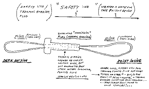
The connector of the present invention comprises a pair of wire rope or cable
loops, and may be 5 mm diameter, with a 1500 pound load capacity (4500 pound
Ultimate
Load). The wire loops are intertwined, one loop passing through the other,
(i.e.

CA 02714848 2010-09-16
3
interlocked) but not in contact each other. Rather, the loops are constrained
within a PVC
plastic plug which encases the wire loops and separates them from contact.
One end of the plastic plug has an enlarged head portion, and when installed
is
intended to contact a deck ledger board on the exterior of a building
structure. A foam
washer serves to provide a sealing contact between the enlarged head and the
ledger board.
At the other end of the plug, a metallic ring surrounds the plastic end and
serves to
strengthen the end in circumstances of lateral forces being applied to the
cable. The
plastic acts as a thermal barrier whereby temperatures imposed on the exterior
of the cable
are not transmitted to the interior cable.
In a typical installation where joists are off-set (see Figure 9) an aperture
or bore is
drilled or otherwise formed through the ledger board and the building
structure including
cladding, sheathing and structural header. The interior of the plastic plug is
then inserted
through the aperture until the enlarged head and foam washer contacts the
ledger board.
The length of the plug approximates the depth of such drilled bore, and is
typically in the
order of 4 - 6 inches. The exterior cable is then fastened securely to a joist
of the deck
structure, while the interior cable is securely fastened to an interior joist.
The exact
method of fastening may entail bolted clamps or other suitable means.
Typically 2 or 3 or
such ties are employed, depending on the length of the deck attachment to the
building.
In the event of catastrophic earthquake or hurricane, forces tending to
separate the
deck and ledger board from the building structure apply a tensile load on the
connected
device. However, the device, being attached to the interior and exterior
joists, ties the
deck structure to the building structure and prevents its removal. In the
further event that
forces exceeding the rupture strength of the plastic plug are applied to the
connector, the

CA 02714848 2010-09-16
4
plug may be crushed, allowing the cable loops to come into contact. However,
as the
loops are intertwined, a solid physical connection remains to prevent the
joists and ledger
board of the deck structure from being detached from the building structure.
This feature
complies with the International Residential Code (IRC) revised by the ICC in
2009. In the
event of such extreme damage, of course the plugs must ultimately be replaced,
but the
device has served its purpose of retaining the deck structure to the building.
In addition to the adaptability of the present plug to attach joists in
alignment and
as well as to attach off-set joists, the present device also acts as a thermal
barrier, thereby
resisting any transmittal of extreme temperatures between the exterior and
interior of the
structure. This feature eliminates condensation, corrosion and ultimately mold
and wood
rot occurrences.
In accordance with the present invention, the connector comprises two loops
having an axial extent of about 3 feet, and an intermediate plastic plug of 5
inches in
length and 1 inch diameter with an enlarged head of 2 inches in diameter and
'/2 inch
thickness. An aluminium or steel collar extends over the opposite end and is
tapered to
ease access of the plug into the bore hole during installation.
While the foregoing illustrates specific embodiments of the invention,
variations in
size, strength, and materials are within the ordinary skill of a person
skilled in the art and
are within the scope of the present invention which is defined by the
following claims.

Representative Drawing
A single figure which represents the drawing illustrating the invention.
Administrative Status

2024-08-01:As part of the Next Generation Patents (NGP) transition, the Canadian Patents Database (CPD) now contains a more detailed Event History, which replicates the Event Log of our new back-office solution.

Please note that "Inactive:" events refers to events no longer in use in our new back-office solution.

For a clearer understanding of the status of the application/patent presented on this page, the site Disclaimer , as well as the definitions for Patent , Event History , Maintenance Fee  and Payment History  should be consulted.

Event History

Description Date
Time Limit for Reversal Expired 2013-09-17
Application Not Reinstated by Deadline 2013-09-17
Inactive: IPC assigned 2012-11-30
Deemed Abandoned - Failure to Respond to Maintenance Fee Notice 2012-09-17
Application Published (Open to Public Inspection) 2012-03-16
Inactive: Cover page published 2012-03-15
Inactive: IPC assigned 2010-10-27
Inactive: IPC assigned 2010-10-21
Inactive: First IPC assigned 2010-10-21
Inactive: Filing certificate - No RFE (English) 2010-10-05
Letter Sent 2010-10-05
Application Received - Regular National 2010-10-05

Abandonment History

Abandonment Date Reason Reinstatement Date
2012-09-17

Fee History

Fee Type Anniversary Year Due Date Paid Date
Application fee - standard 2010-09-16
Registration of a document 2010-09-16
Owners on Record

Note: Records showing the ownership history in alphabetical order.

Current Owners on Record
ULI WALTHER
GERDA WALTHER
MIRCO WALTHER
Past Owners on Record
BERND WALTHER
Past Owners that do not appear in the "Owners on Record" listing will appear in other documentation within the application.
Documents

To view selected files, please enter reCAPTCHA code :


To view images, click a link in the Document Description column. To download the documents, select one or more checkboxes in the first column and then click the "Download Selected in PDF format (Zip Archive)" or the "Download Selected as Single PDF" button.

List of published and non-published patent-specific documents on the CPD .

If you have any difficulty accessing content, you can call the Client Service Centre at 1-866-997-1936 or send them an e-mail at CIPO Client Service Centre.


Document
Description 
Date
(yyyy-mm-dd) 
Number of pages   Size of Image (KB) 
Drawings 2010-09-15 5 591
Description 2010-09-15 4 162
Claims 2010-09-15 2 46
Abstract 2010-09-15 1 13
Representative drawing 2011-11-13 1 18
Courtesy - Certificate of registration (related document(s)) 2010-10-04 1 102
Filing Certificate (English) 2010-10-04 1 155
Reminder of maintenance fee due 2012-05-16 1 112
Courtesy - Abandonment Letter (Maintenance Fee) 2012-11-12 1 173