Note: Descriptions are shown in the official language in which they were submitted.
CA 02715644 2010-08-13
WO 2009/103016 PCT/US2009/034141
SWITCf[NG D} X'WE AND :iE11I-[OD OF MANUFA.C'I I'IZING SAM)F
FIELD OF THE INVENTION
[0001]:: This invention relates generally to switching devices, and relates
rrrore
particularly to switching devices that couple two or More computers to two or
more
peripheral devices and methods of manutact.uring the same.
DESCRIPTION OF THE BACKGROUND
[0002]' Peripheral or KVMI (keyboard, video, and mouse) switches allow a
keyboard,
a nt.ouse,, a video monitor, or other peripheral devices to interact with or
be controlled by
a computer selected from a group of computers. Although peripheral switches
take a
variety of forms, their essential purpose is to allow a keyboard, a mouse, a
video monitor,
and other peripheral devices to interact with the selected computer such that
the computer
receives and transmits signals to and from the various peripheral devices
regardless of the
data protocol schemes employed by either the selected. computer or the
peripheral
devices.
[0003]', Typically, however, peripheral switches do not allow a firsà computer
to
continue controlling a first peripheral device while control of the other
peripheral
dev.ice(s) is switched to a second computer. In some situation-,, a user might
want the
first computer to continue performing a task e (e.g., ,performing a data
transfer or playing
rrmusic) using a first peripheral device while the second computer uses the
other peripheral
devices. In some situations, such as performing. a data transfer, any
interruption of the
control or the connection between the computer and the peripheral device could
cause file
system corruption or data loss.
[0004]I Accordingly, a need or potential for benefit exists fora switching
apparatus or
systen.1 that allows a first corriputer to continue to control. a first
peripheral device while
control of other peripheral devices. is switched to other computers.
BRIEF DESCRIPTION OF THE DRAWINGS
(.0051', To facilitate further description of the embodiments, the following
drawings
argiprovided in which:
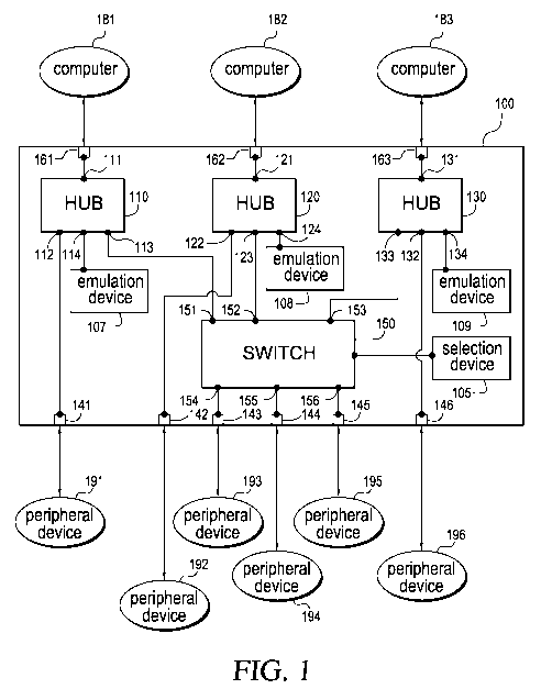
[0006]:: FIG. I illustrates a switching device coupling three computers to six
peripheral
devices, according to a first embodiment,;
CA 02715644 2010-08-13
WO 2009/103016 PCT/US2009/034141
2
[0007] F1 =i..2 illustrates a switching device coupling three computers to six
peripheral
devices, according to a second embodiment;
[0Ã004], FIG. 3 illustrates a switching device coupling two computer's to five
peripheral
devices, according to a third enrbodnrrerat;
[0009]', FIG. 4 illustrates a switching device coupling two computers to seven
peripheral devices, according to a fourth embodiment;
[0010]', 1, R1 a. 5 illustrates a sw.itclzineu device coupling two computers
to four peripheral
devices, according to a fifth embodiment, and
[0011]:: FIG. . 6 illustrates a. flow chart for an embodiment of a method. of
manufacturing a switching apparatus.
[0012] For simplicity and clarity of illustration, the drawing figures
illustrate the
general manner of construction, and descriptions and details of well-known
features and
techniques may be omitted to avoid unnecessarily obscuring the invention.
Additionally,
elements in the drawing figures are not necessarily drawn to scale. For
example, the
dimensions of some of the elements in the figures may be exaggerated relative
to other
elements. to help improve understanding of embodiments of the present
invention. The
same reference numerals in different figures denote the same elements.
[001-)]:: The terms "first," "second;- "third," "fourth," and the like in the
description
and. in the claims; if any, are used for distinguishing between similar
elements and not
necessarily for describing a particular sequential or chronological order. It
is to be
understood that the terms so used are interchan4eable under- appropriate
circumstances
such that the embodiments of the invention described herein are, fear
example., capable of
operation in sequences other than those illustrated or otherwise described
herein.
Further-i.nore, the terms "include," and "have,," and any variations thereof;
are intended to
cover a non-exclusive inclusion, such that a process, method, system, article,
err apparatus
that comprises a list of elements is not necessarily limited to those
elements, but may
include other elements not expressly listed or inherent to such process,
method, article., or
apparatus.
[0014]:: The terms "left," "right," "float " "back," ":top" "bottorar,"
"over," "under,"
and the like in the description and in the claims if any, are used for
descriptive purposes
and not necessarily for describing permanent relative positions. It is to be
understood that
the terms so used are interchangeable under appropriate circumstances such
that the
embodiments of the invention described herein are, for example, capable of
operation in
CA 02715644 2010-08-13
WO 2009/103016 PCT/US2009/034141
3
other orientations than those illustrated or other-N se described Therein. The
term "oil." as
used herein, is defined as on. at, or otherwise adjacent to or next to or
over,
[OO15] The terms "couple,,, "coupled," "couples,,, "coupling," and the like
should be
broadly understood and refer to connecting two or more elements or signal;,
electrically
and,/or mechanicarlly ; either directly or indirectly through intervening
circuitry and/or
elements. Two or more electrical elements may be electrically coupled, either
direct. or
indirectly, but not be mechanically coupled; two or more mechanical elemeri.ts
may be
mechanically coupled, either direct or indixecily. but not be electrically
coupled; two or
more electrical elements may be r iechanically coupled, directly or
indirectly, but not be
electrically, couple(], Coupling (whether only mechanical, only electrical, or
both) may be
for any length of time, e_g., permanent o rsemi-permanent or only for an
instant-
001 a1 "Electrical coupling" and the like should be broadly, understood and
include
coupling involving any electrical signal, whether a power signal, a data
signal, andior
other types or combinations of electrical signals. " ilechanical coupling"
and. the like
slxcaatld be broadly, u nde:r-stood and include mechanical coupling of all
types.
[0017]', The absence of the word "removably," "reniovable," and the like near
the
word "coupled," and the like does not mean that the coupling, etc, in question
is or is not
removable. For example. the recitation of an electrical connector being
coupled to aa
peripheral device does not mean that the peripheral cannot be removed
(,.readily of
other ise) from the electrical connector,
[0018]', "Peripheral. device," as used herein, can refer to any electrical
device that can
be coupled to a cornptrter to expand its functionality or abilities. For
example, a
peripheral device can be a mouse, a keyboard, a video monitor or display, a
printer, a
scanner, a disk drive, a tape drive, a microphone, a speaker, a digital n
redia player, a
joystick, a CD-ROM ("computer disk read only memory) player, a DVD (dikpial
video
disk) player, a USB (universal serial bus) hub, flash r iemory drive a thumb
drive),
or a camera. ' Nl:ouse," as used herein, includes all computer input point
devices (r-D_ice,
trackbaal.ls, touchpad, pointing sticks, etc. ).
DETAiL.ED DESCRIPTION OF EXAMPLES OF EMBODIMENTS
[001 9]:: In a number of embodiments, a switching device is configured to
couple a first
computer to a first peripheral device and one or more second peripheral
devices. The
i itching device is further configured to couple a second computer to a third
peripheral
device and the one or more second peripheral devices. The switching device
includes: (a)
a svitch configured- to couple to the one or more second peripheral devices;
(b) a first hub
CA 02715644 2010-08-13
WO 2009/103016 PCT/US2009/034141
4
incl adino: (1) a first upstream port configured to couple to the first
computer; (2) a first
downstream port configured to couple to the first peripheral device; and (3)
at least one
second downstream port coupled to the switch: (c) a second hub iracludir g (1)
a first
upstream port configured to couple to the second computer: (2) a first
downstream port
configured to couple to the third peripheral device; and (:3) at least one
second
downstream port coupled to the switch.
[0020]:: In other embodiments, an electronic switchbox is configured to switch
a
keyboard and a mouse between two or more computers and also couple the two or
more
computers to two or more peripheral devices. The electrical swvitclabox
.includes: (a) a
keyboard switch. configured to couple to the. keyboard; (b) a mouse switch
configured to
couple to the aamouse; and (c) two or more hubs. In some examples, each hub of
the two or
more hubs is configured to couple one computer of the two or more computers to
the
keyboard switch and the mouse switch. Each of the one or more hubs can be
further
configured to couple directly to at least one peripheral device of the two or
more
peripheral devices.
[0021] In a further embodiment, an apparatus can be configured to switch one
or
more first peripheral devices between at least two computers. Furthermore, the
apparatus
is also configured to couple a. first computer of the at least two computers
to one or more
peripheral devices and to couple a second computer of the at least two
computers
second
to one or more third peripheral devices. The apparatus can include: (a) a
switch
configured to couple to the at least two computers and the one or more first
peripheral
devices; (b) a first connector configured to couple to the first computer of
the at least two
computers; (c) a second connector coupled to the first connector and
configured to couple
to the one or more second peripheral devices; (d) a third connector configured
to couple
to the second computer of the at least two computers; and. (e) a fourth
connector coupled
to the third connector and configured to couple to the one or more third
peripheral
devices.
[0022In yet other embodiments, an apparatus is configured to switch one or
more
first peripheral devices between at least two computers. The apparatus is also
configured
to couple a first computer of the at. least two computers to one or more third
peripheral
devices and couple a second computer of the at least two computers to one or
more fourth
peripheral devices. I.he apparatus includes: (a) a switch configured to couple
to the at
least two computers and the one or more first peripheral devices; (b) a first
hub
configured to couple to the first computer of the at least two computers and
the one or
CA 02715644 2010-08-13
WO 2009/103016 PCT/US2009/034141
more third peripheral devices; and (c) a second hub configured couple to the
second
computer of the at least two computers and the one or more, fourth peripheral
devices.
0Ã023] Still further embodiments teach a method of manufacturing a switching
apparatus. In these e ibod. TienÃs, the switching apparatus can be configured
to
electrically couple one or more peripheral devices to two or more computers.
The
method comprises: (a) providing a first hub with an input port and two or more
output
ports; (b) providing a second hub with an input port and two or more output
ports; (c)
providing ass itch; (d) electrically coupling
a first port of the two or more output ports of
the :f:rrst hub to the switch; (e) electrically coupling a first port of the
two or more output
ports of the second hub to the 5 witch,- (f, providing three or more output
connectors with
each of the three or more output connectors configured to couple to one of the
one or
more peripheral devices; (g) electrically coupling a second port of the two or
more output
ports of the first h.ub to a .first output connector of the three. or more
output connectors; (h)
electrically coupling a second port of the two or more output ports of the
second hub to a
second output connector of the three or more output connectors; and ()
electrically
coupling the switch to a third output connector of the three or more output
connectors.
[00241 Turning, to the drawings, FIG. 1. illustrates a switching device 100
coupling
computers 1.81, 182, and 183 to peripheral devices 191, 142, 193, 194, 195,
and 196,
according to a first embodiment. In some examples, switching device 100 can be
considered to be or to include a switchbox. or an apparatus for switching.
Switching
device 100 is merely exemplar-,, and is not limited to the embodiments
presented ltereiaa.
Switching device. 100 can be employed in many different embodiments or
examples not
specifically depicted or described herein.
[0025 Switching device 100 can be configured to couple; (a) computer 181 to
peripheral devices 191, 193, 194, and 195; (b) computer 182 to peripheral
devices 192,
1.93, 194, and 195; and (c) computer 183 to peripheral devices 193, 194, 195,
and 196.
[0026]:: In the embodiment illustrated in FIG. 1, switching device 100 can
switch
control of peripheral devices 193, :194, and 195 between computers 181, 182,
183).
However, each of peripheral devices 191, 192, arid 196 are. non-switchably
controlled by,
computers 181, 182, and 183, respectively, For example, switching device 100
allows
computer 181 to retain control of peripheral device 191 while control of
peripheral
devices 193, :194, and 1.95 are switched to computer 182 or 183. This
configuration
allows computer 181 to continue performing a task (e.g., transfer of data,
creating a
back-up tape, or playing ra.music) using peripheral device .191 while one of
computers 18"
CA 02715644 2010-08-13
WO 2009/103016 PCT/US2009/034141
6
or 183 controls or uses peripheral devices 1933, 194, and 195. Moreover,
limiting the
number of peripheral devices switched between computers. 181. 182, and I S3
helps lower
the cost of the Maratrf:rcturinn switching device 14Ã1-
[0027]I In sonic enrbodinrents, switching device 100 can include: (a) at least
switch
150 (b) two or more hubs 1111, 120, and 130; (c) one or more emulators or
emulation
devices 1Ã37, 108, and 1419; (d) a selection device 145; and (e) three or more
electrical
connectors 1.61 162, 163, 141, 142, 143, 144, 145;. and 146. In some examples,
at least
one of hubs 110, 124, and 130 can be a UUS hub. in the other e a mrples,
switching
device 100 does n t include emulation devices 107, 108, and 109.
[0028]', Electrical connectors 141, 142, 143, 144, 145, and 146 can be
configured to
couple to peripheral devices 191, 1.92. 193, 194, 195, and 196, respectively.
Electrical
connectors 161, 162, and 163 can be configured to couple to computers 1. 1.
182, and
183, respectively. In some embodiments, one or more of electrical connectors
161, 1Ã2,
163, 141, 142, 143, 144, 145, and 1.46 can be USB connectors. In the same or
different
embodiments, one or more of electrical connectors 161, 162, 16_3), 141, 142.
14_3), 144,
145, and 146 can be video connectors. That is, at least one of electrical
connectors 161,
162, 163, 141, 142, 143, 144145, and 146 can be a SCART (Syndicat des
Constructeurs
d'Appareils Radioreceptetrrs et Televiseurs) connector, an `-video (separate
video)
connector, a VGA (Video Graphics Array) connector, an HDMI (High-Definition
Multimedia interface) connector, a DVI (Digital Visual 'Interf-ace), an ADC
(Apple
Display Connector), or the like.
[0029]:: Switch 150 can be configured to switch peripheral devices 193; 194,
and 195
between computers 1 S 1, 182, and 183. in some examples, switch 150 can
include. (a)
two or more input ports 151, 152, and 153; and (b) one or more output ports
154, 155, and
156. Each of output Ports 154, 155, and 156 can be configured to couple to one
of
peripheral devices 193, 194. and 195. Specifically, output ports 154, 155, and
156 can be
coupled to peripheral devices .193, 1 94, and 195, respectively, through
electrical
connectors 143, 144, and 145, respectively . In sonic examples, switch 15Ã3 is
a KVM
switch.
[003Ã1]', In the same or different embodiments, switch 150 can be a cross-
point switch.
A cross-point switch is a non-blocking switch that allows any input port to
connect to any
output port without obstructing the connection between any- other input and
output ports.
Accordingly computer 181 could be coupled to peripheral device 195, and
computer 182
CA 02715644 2010-08-13
WO 2009/103016 PCT/US2009/034141
7
could be switched between peripheral devices 193 and 194 without disturbing
the
connection between peripheral device 195 and computer 182.
[0Ã031] Hub 110 can include: (a) an upstream port 1.11 configured to couple to
computer 1.41 through electrical connector 161; (b) a downstream port 112
configured to
couple to peripheral device 191 through electrical connector 1 41., (c)at
least One
downstream port 113 coupled to switch I 5f} at input portt. 151; and (d) a
downstream port
11.4 coupled to emulation device 107.
[0032]: Hub 120 can include: (a) an upstream port 121 configured to couple to
computer 182 through electrical connector 162; (b) a downstream port 122
configured to
couple to peripheral device 192 through electrical connector 142t: (c) at
least one
downstream port 1.23 coupled to switch 1.50 at input port 15.2; and (d) a
downstream Port
1.24 coupled to emulation device 108.
[0033], Hub 130 can include: (a) an upstream port 131 configured to couple to
computer 1.53 through electrical connector 1.63; (b) a downstream port 132
configured to
couple to peripheral device 196 through electrical connector 146 (c) at least
one
downstream port 133 coupled to switch 150 at input port 153; and (d) a
downstream port
1.34 coupled to emulation device 109,
[0034]:: In sorme embodiments, computers 181, 182, and 183 could require.
emulation
devices 107, 108, 109, respectively, to be coupled: to the computer to
function properly.
Emulation devices 107, 108, and 109 can make computers 181, 182, and 183,
respectively, believe that peripheral devices 193, 194, and 1.95 (or other
similar peripheral
devices) are coupled to the computer when peripheral devices 193, 194 and 195
are
coupled to another computer by switch 150. For example, many computers need,
and
several operating systems require, a mouse and keyboard. to be coupled to the
computer
for the computer to function properly. Accordingly, as an example, if
peripheral device.
193 is a a arouse and if peripheral device 1.94 is a keyboard, emulation
devices 107 and 108
can emulate a keyboard and a mouse to computers 181, and 182, respectively,
when
peripheral devices 193 and 194 are controlled by computer 153.
[0035].. In some examples, emulation devices 017, 108, and 109 are configured
to
emulate one or more of peripheral devices 193, 194, and 195. That is,
emulation device
107 can emulate one or more of peripheral devices 193, 194, and 195 for
computer 1871..
Emulation device 108 can emulate one or more of peripheral devices 193, 194,
and 195
for computer 152. Emulation device 109 can emulate one or more of peripheral
devices
193, 194, and 195 for computer 183,
CA 02715644 2010-08-13
WO 2009/103016 PCT/US2009/034141
8
[0036] Selection device 105 is configured to allow a user to control switch
150. That
is, selection device 105 is configured to control the switching of switch
1.50. Selection
device 1 05 allows a. user to utilize computers 181, 182, and 183 to control
peripheral
devices 193, 194, and 195. Selection device 105 can be implemented using any
type of
electrical, mechanical, or electromagnetic meclranisn. for performing the
selection and
switching function.
[0037]', In some embodiments, selection device 105 can be a physical switch,
For
example, selection device 105 can be a niechanicaal dial, which can be turned
to any one
of three discrete positions for selecting of e of computers 18 I, 182, and
183, respectively.
Alternatively, selection device 10.5 can be three mechanical buttons or the
like. A user
can push one of the buttons to choose one of computers 181, 182, and 183 to
control
peripheral devices 193, 194, and 195.
[0038]:: In yet another embodiment, selection device 1.05 can be a software
andior
hardware components that allows the user to perfora:ar the selection process
through
peripheral devices 193), 194, and 195 and/or computers 181, 1 82 and/or 183.
That is, a
window, a button, or the like can appear on the computer screen of a video
monitor, and
the user can switch control of peripheral devices 193, 194, and 1.95 between
computers
181, 182, and 1.8 3.
[0039]', In the embodiment illustrated in FIG. i, switching device 100
switches three
computers between three peripheral devices. None of the embodiments described
herein,
however, are limited to switching three peripheral devices between three
computers, For
example in other embodiments switching device 100 could. switch one, two,
four., or more
peripheral devices between two, four, or more computers.
[0040]I Similarly, switching device 100 couples each of computers 181, 1.82,
and 183
to one non switched peripheral device (i.e., peripheral devices 191, 192 and
196,
respectively), In other embodiments, switching device 1.00 could couple each
of
computers 181, 182, and 183 to zero, two, or more non-switched peripheral
devices.
[0041 ]I FIG. 2 illustrates a switching device 200 coupling computers 181,
182, and 183 to peripheral devices 191, 192, 193, 194, 195, and 196, according
to a second
embodiment. Referring to FIG 2, switching device 200 can be configured to
couple. (a)
computer 1.81 to peripheral devices 191, 193, 194, and 195, (b) computer 1.82
to
peripheral devices 192, 193, 194,. and 195, and (c) computer 183 to peripheral
devices
193, 194, 195, and 196. From the perspective of computer 141. 182, and 1,93
and
CA 02715644 2010-08-13
WO 2009/103016 PCT/US2009/034141
9
peripheral devices 191, 192, 193, 194. 195, and 196, switching device 200
functions
identically to switching device 100 (FIG. 1).
[0Ã042] In some embodiments, a switching device 20Ã3 can include: (a) at least
one
switch 250; (,fa) three or aaao.re hubs :110, 12Ã1. 1.30, and 240; (c) one or
more emulation
devices 107, 108, and 109: id) a selection device 105; and (e) five or more
electrical
coraraectors 1411, 142, 143, 14/41, 145, 146, 16 1, 162, and 163.In other
examples, switching
device 200 does not include emulation devices 107, 108, and 109.
[0043]: in some examples, hub 240 can include an upstream port 236 and two or
more
downstream ports 237, 238, and 239. Downstream ports 237, 238, and 239 are
coupled to
peripheral devices 193õ 194, and 195 through electrical connectors 143, 144,
and 145,
respectively. In some examples, hula 240 is a [1513 hub.
[0044]', In various enabodiaaaents, switch 250 can be a three input and one
output
switch. That is, switch 250 switches the one output port 254 between the three
input ports
251, 252, and 253. In various examples, downstream ports 11:3, 123. and 133
are coupled
to input ports 251, 252. and 2"53, respectively. Output port 254 is coupled to
an upstream
port. 236 of hà b 240.
[0045]', Referring to another embodiment, FIG. 3 illustrates a switching
device 300
coupling computers 181 and 182 to peripheral devices 191, 192, 193, 194, and.
195,
<according to sa fi:Ia.ird eraaf~ocl raaent. Ira dais e:aaahod.itaaent,
switchin device 300 is configured
to switch peripheral devices 193, 194, and 194 between computers 181 and 182
and non-
switc.hably couple each of computers 181 and 182 to peripheral devices 191 and
192,
respectively. Tat is, switching device 300 is configured to couple, (a)
computer 181 to
peripheral devices 191, 193, 194, and 195; and (b) computer 182 to peripheral
devices
192, 193, 194, and 195. In some embodiments, peripheral devices 193, 194, and
195 can
be a keyboard, a nmouse, and a video monitor, respectively.
[0046]', In some embodiments, switching device 300 can include. (a) one or
more
switches 357, 358, and 339; (b) two or more hubs 310 and 320; (c) at least one
emulation
device 306; (d) a selection device 305; and (e) three or more electrical
connectors 141,
142. 143, 144, 145, 161, and 162..
[0047]', in some exatraples, switch 357 can be coupled to a downstream port of
each of
hubs 310 and 320 and configured to couple to peripheral device 193 through
electrical
connector 143. In sonic examples, switch 357 can be a multiplexer. In various
embodinments, switch 357 can be a keyboard switch or keyboard multiplexer.
CA 02715644 2010-08-13
WO 2009/103016 PCT/US2009/034141
[0048] In the same or different. examples, switch 358 can be coupled to the
downstream ports of each of hubs 3113 and 320 and. configured to couple to
peripheral
device 194, through electrical connector 144. Switch 358 can be a multiplexer.
In
various embodiments, switch 358 can be a mouse switch or a mouse multiplexer.
[0049]', Similarly; switch 359 can be coupled to the downstream ports of each
of hubs
31.0 and 320 and configured to couple to peripheral device 195 through
electrical
connector 145. Switch 359 can be a multiplexer in some examples. In various
embodiments, switch 359 can be a video switch or video multiplexer. When
switch 359
is a video switch or video multiplexer, electrical connector 145 can be a
video connector.
[0050]', Selection device 305 can be coupled to switches 357, 358, and 359, In
some
embodiments, selection device 305 can allow the user to independently select
which of
computers I8I and 182 control each of peripheral devices 193, 194, and 1.95.
For
example, selection device 305 can include a selection dial for each of
peripheral devices
193, 194, and 1135. In other embodiments, selection device can be identical or
sina:ilar to
device. 105 of FIG. 1.
selection
[0051]: In some exaraaples, emulation device 306 is configured to emulate one
or am-more
of peripheral devices 193. 194, and 195. For example; if peripheral device 193
is a
computer nmouse, peripheral. device 194 is a keyboard, and peripheral device
195 is a
video monitor, emulation device 306 can emulate a:mouse, a keyboard and or a.
video
monitor to computers I S 1 and. 1 82.
[0052]', In some embodiments, emulation device 306 only enaailates peripheral
devices
193. 194, and 195 to the one of computers 181 and 182 not currently-
contro:llin"
peripheral devices 193, 194, and 135. In. other etrmbodiments, emulation
device 306
emulates the coupling of peripheral devices 193, 194, and 195 or other
peripheral devices
to computers 181 and 182 regardless of which of computers Si 1and 182 are
controlling
peripheral devices 1.9 3, 194, and 1.95. For example, if peripheral. device
193 is a_ rrmouse
and if computer 181 is controlling peripheral device 193, emulation device 306
could
make it appear to computer 181 that two mice are coupled to conmrpuuter- 1.81.
[0053]' In alternative examples, emulation device 306 can include or be
replaced by
one or more erne lation modules. Each of the emulation raaodules can be
configured. to
emulate at least one of peripheral devices 193, 194, and 1 X3.5. In some
examples, each of
the one or more emulation modules can be coupled to one hub of hubs 310 and
320.
[0054]I FICG. 4 illustrates a switching device 400 coupling computers 1.81 and
182 tea
peripheral devices 1.91, 192, 193, 194, 195, 497, and 498, according to a
fourth
CA 02715644 2010-08-13
WO 2009/103016 PCT/US2009/034141
11
embodiment. In this embodiment, switching device 400 is configured to switch
peripheral devices 193, 194, and 195 between computers I l and. 182' and non-
switchably
couple computer 181 to peripheral devices 191 and 497, and facer- v itchably
couple
computer 152 to peripheral devices 192 grad 498..
[00551', In some embodiments, switching device 400 can include: (a) at 1ea.st
one
switch 150; (b) two or more hubs 110 and 120; (c) emulation devices 1137 and
108; (d)
selection device 105; and (e) electrical connectors 141, 142: 143, 144, 145,
447, 448, 46
462, 464, and 465. In some examples, electrical connectors 461 and 464 can be
configured to couple to computer 151; electrical connectors 462 and 465 can be
configured to couple to computer 152; electrical connectors 141, 142, 143,
144, 1.45, 447,
and 448 can be confgured to couple to peripheral devices 191, 192, 193, 194,
195, 497,
and 498, respectively, In other embodiments, switching device 400 does not
include
emulation devices 107 and 105,
[005Ã] In these enibod.inmaents, computers 151 can be coupled to switch 150
and hub
110. Specifically, electrical connector 461 is coupled to input port 151 of
switch 150;
electrical connector 464 is coupled to upstream port I I 1 of hub 11Ãx.
[0157] Likewise, computer 182 can be coupled to sw.itclr. 150 and hub 120.
't'hat is,
electrical connector 462 is coupled to input port 1.52 of switch 150;
electrical connector
465 is coupled to upstream port 1.21 of hub 1220-
[0058]:: Hub 110 can be configured to couple to peripheral devices 191 and
497,
Specifically, downstream ports 1122 and 415 can be coupled to electrical
connectors 141
and 447, respectively. Similarly, hub 120 can be configured to couple to
peripheral
devices 192 and 49$. Thai is, downstream ports 122 and 425 can be coupled to
electrical
connectors 142 and 448, respectively.
[00591 FIG. 5 illustrates a switching device 500 coupling computers 151 and
182 to
peripheral devices 191, 1.92, 193, and 194, according to a fifth embodiment.
Referring to
FIG. 5, switching device 500 can include: (a) a switch 550; and (b) electrical
connectors
141, 142, 143, 144, 461, 462, 464, and 465. In this embodiment, switching
device 500 is
configured to switch peripheral devices 193 and 1.94 between computers 151 and
182 and
non¾switchably couple computer 151 to peripheral devices 191, and nort-
switchably
couple computer 182 to peripheral devices 192.
[0060]:: In some embodiments, electrical connector 464 and 465 can be coupled
to
electrical connectors 141 and .142, respectively. Electrical connectors 461
and, 462 can be
CA 02715644 2010-08-13
WO 2009/103016 PCT/US2009/034141
12
coupled to input ports 551 and 552 of switch 550, respectively, Electrical
connectors 143
grad. 144 can be coupled. to output ports 554 and 555 of switch 550,
respectively.
[006-1] FIG. 6 illustrates an embodiment of a method 600 of manu.fiacruthig a
switching apparatus. For example, the swi.tclairag apparatus can be identical
or similar to
switching device 113Ã3 of FIG. 1. In some embodiments, the switching apparatus
can be
configured to electrically couple three or more peripheral devices to two or
more
computers.
[0062]: Method 600 includes an activity 670 of providing two or more hubs.
Each
hub of the two or more hubs can have an Upstream port and two Ora acre
dowanstreaalmr
ports. As an example, the two or more hubs can be similar or identical to hubs
l 10. 120,
and/or 130 of FIG. 1. The upstream port of each hub can be similar or
identical to
upstream ports 1 1 1, 121 , and./or 131 of hubs 110, 120 and 130,
respectively, as illustrated
in FIG. 1. The two or downstream ports of each hub can be identical or similar
to
downstream ports 112, 113, and 14 of hub 110, downstream ports 122, 123, and
124 of
hub 120, and/or downstream ports 132, 133, and 134 of hub 130, as illustrated
in FIG. 1.
[0063]', Method 600 in FIG. 6 continues with an activity 671 of providing a
swiÃch.
For example, the switch can 'be similar or identical to switch 150 or 250, as
illustrated in
FIG-s. I and 2, respectively.
[0064]', In other examples, the switch can be composed of or replaced with one
or
more switching modules. Each of the switching modules can switch one of the
peripheral
devices between the two or more computers. For example, each of the switching
modules
can be identical or similar to the switches 357, 358, and 359 of FIG. 3.
[0065]', Subsequently=, method 600 of FIG. 6 includes ,in activity 672 of
providing a
selection module. For example, the selection module can be identical or
similar to
selection device 1.05 or 305 of I; IGs. I and 3, respectively.
[0066] Next, method 600 of FIG. 6 includes an activity 673 of providing at
least one
emulation device. For example, the at least one emulation device can be
similar or
dentinal to emulation devices 107, 108, and/or 109 as illustrated in FIG, I or
emulation
device 306 as illustrated FIG. 3-
[0067]:: Method 600 in FIG. 6 continues with an activity 674 of providing four
or more
electrical connectors. For example, the four or more. connectors can be
similar or
identical to electrical connectors 141, 142. 143, 1.44, 1.45, 1413, 161, 162,
and:/or 163, as
illustrated in FIG. 1.
CA 02715644 2010-08-13
WO 2009/103016 PCT/US2009/034141
13
[0065] in some examples, activity 674 can be considered to include the
procedures of.
(a) providing two or more output connectors; and (b) providing two or more
input
connectors. That is, the fht r or more electrical connectors can include the
input
connectors. Each of the input connectors can be configured to couple to one of
the two or
more computers. In some examples, the input connectors can be similar or
identical to
electrical connectors 1.6 1, 162, and 163, as illustrated in Flo, I [0069]::
The four or more electrical connectors can also include two or more output
connectors. Each of the output connectors can be configured to couple to one
of the one
or more peripheral devices. In some examples, the output connectors can be
similar or
identical to electrical connectors 141, 142, 143, 144, 1.45, and 1.46, as
illustrated in FIG.
1.
[0070]', Subsequently, method 600 of FIG. 6 includes an activity 675 of
selecting a
hub from the two or more hubs. In the example illustration FIG 1, one of hubs
110, 120,
or 1 30 (FIG, 1) can be selected..
[0071]:: Referring again to FIG. 6, after selecting a hub from the two or more
hubs,
method 600 of FIG. 6 includes an activity 676 of electrically coupling an
electrical
connector of the four or more electrical connectors to the upstream port of
the selected
hub, For example, elecÃricarlly, coarapling an electrical connector of the
four or more
electrical connectors to the upstream port of the selected hub can he similar
or identical to
the coupling of upstream port i l I to electrical connector 161, the coupling
of upstream
port 1221 to electrical connector 162, and: or the coupling of upstream port
13 1 to electrical
connector 163, as illustrated in FIG. 1.
[00712]: Method 600 in FIG. 6 continues with an activity 677 of electrically
coupling a
first port of the two or more downstream ports of the selected hub to the
switch. For
exaanmple, the electrical coupling of the first port of the two or more
downstream ports of
the selected hub to the switch can be similar or identical to the coupling of
downstream
port 113 to input port 151. of switch 150, the coupling of downstream port 123
of hub 120
to input port 152 of switch :150, and/or the coupling of downstream port 132
to input port
153 of switch 150, as illustrated in FIG. 1,
[0073], Subsequently, method. 600 of FIG, 6 includes an activity 678 of
electrically
coupline a second port of t ae two or more downstream ports of the selected
hub to an
electrical connector of the four or more electrical connectors, For example,
the electrical
coupling of the second port of the two or more downstream ports of the
selected hub to
the electrical connector of the four or more electrical connectors can be
similar or
CA 02715644 2010-08-13
WO 2009/103016 PCT/US2009/034141
14
identical to the coupling of downstream port 112 to electrical connector 1.
11, the coupling
of downstream port 122 to electrical connector 142, and/or the coupling of
downstream
port 132 to electrical connector 146, as illustrated in F.IG, 1.
[0074], Next, method 600 of FIG. 6 includes an activity 679 of deciding
whether to
select another hub. If any of the two or more hubs have not already been
selected., the
next activity in t method 600 is activity 675 of selecting a hub from the two
ctr more hubs.
If every hub of the two or more hubs has been already been selected, the next
activity in
method 600 is an activity 680. In the example illustrated in FIG. 1. If all of
hubs 110,
120, and 130 have not been selected, the next procedure is activity 675 (FIG.
à ). If all of
hubs I.10, 120, and 130 have been selected, the next procedure is activity 680
(FIG. 6),
[0075] Referring a4gair to FIC_i. 6, activity 680 of method 600 in l"ICS. 6 is
an activity
of electrically coupling the switch to at least one electrical cony nector of
the four or more
electrical connectors. For example, the electrical coupling of the switch to
at least one
electrical connector of the four or more electrical connectors can be similar
or identical to
the coupling of output ports 154, 155, and 156 of switch 150 to electrical
connectors 143,
144, and 1.45, respectively, as illustrated in FIG. 1.
[0076] In some enibodinients, the sw.itcll cart be coupled to the four or more
electrical
connectors through it hub. For example, the electrical. coupling of the switch
to at least
one electrical connector of the four or more electrical connectors can be
similar or
identical to the coupling of switch 250 to electrical connectors 143, 144, and
1.45 through
hub 2 0. as illustrated in l"HG.:2.
[0077] Subsequently, method 600 of FIC_;. 6 includes an activity 681 of
electrically
coupling the selection device to the switch. The electrical coupling of
selection device to
the switch can be similar or identical to the coupling of selection device 105
to switch
150, as illustrated in FIG. I or the coupling of selection devices 305 to
switches 357, 358,
and 359 as illustrated in FIG. 3.
[0078] Next, method 600 of FIG. 6 includes an activity 682 of electrically
coupling
the at least one emulation device to the at least one of the two or more hubs.
For
example, coupling of the at least one emulation device to the at least one of
the two or
more hubs can be similar or identical to the coupling of emulation devices
107, 108, and
1Ã 9 to hubs 110, 1211, and 130, respectivelyõ as illustrated in Fl.G. 1. In
another example,
the coupling can be similar or identical to the coupling of emulation device
306 to hubs
.310 and 3211. as illustrated in FIC.3. 3.
CA 02715644 2010-08-13
WO 2009/103016 PCT/US2009/034141
[0079] In other embodiments, the order of activities 670-682 can vary. For
exaanmple,
activities 680-682 could occur before or concurrent with activities 675-679.
In another
exa:anple, activity 674 can occur before or conct rr-ent witl1 aactivities
670, 671, and 673- In
still another exaatample, activities 675-679 could occur before, after, or
concurrent with
activities 670-674 and à 80-682.
[(lf)113]' Although the invention has been described with reference to
specific
enibod.iments, it will be understood by those skilled in the art that various
changes may be
made without departing from the spirit or scope of the invention. For example,
it will be
readily apparent the switching device could be configured such that: a user
can decide
whether emulation devices 107, 1.08, and 109 (FIG. 1) eta elate one or more of
peripheral
devices 193, 194, and 195 (FIG. 1). Additional examples of such changes have
been
given in the fore9oing description. Accordingly>, the disclosure of
embodiments of the
invention i.s intended tc be illustrative of the scope of the invention and is
not intended to
be limiting. It is intended that the scope of the invention shall be limited
only to the
extent required by the appended claims. To one of ordinary skill in the art,
it will be
readily apparent that the case and method of use discussed herein may be
implemented in
a variety of en bodiraaents, and that the foregoing discussion of certain of
these
embodiments does not necessarily represent a complete description of all
possible
embodiments. Rather, the detailed description of the drawings, and the
drawings
themselves, disclose at least one preferred embodiment of the invention, and
may disclose
alternative embodiments of the invention,
[0081]:: All elements claimed in any particular claim are essential to the
invention
claimed in that particular clainm. Consequently, replacement of one or more
claimed
elements constitutes reconstruction and not repair. Additionally, benefits,
other
advantages, and solutions to problems have been described with regard to
specific
etrtbodinmaents. The benefits, advantages, solutions to problems, and any
element or
elements that may cause any benefit, advantage, or solution to occur or become
more
pronounced, however, are not to be construed as critical, required, or
essential features or
elements of any or all of the claims.
[0082] Moreover, embodiments and limitations disclosed l .ere.in are not
dedicated to
the public under the doctrine of dedication if the embodiments and/or
limitations: (1) are
not expressly claimed in the claairmts; and (2) are or are potentially
equivalents of express
elements and/or limitations in the claims under the doctrine of equivalents.