Language selection

Search

Patent 2715952 Summary

Third-party information liability

Some of the information on this Web page has been provided by external sources. The Government of Canada is not responsible for the accuracy, reliability or currency of the information supplied by external sources. Users wishing to rely upon this information should consult directly with the source of the information. Content provided by external sources is not subject to official languages, privacy and accessibility requirements.

Claims and Abstract availability

Any discrepancies in the text and image of the Claims and Abstract are due to differing posting times. Text of the Claims and Abstract are posted:

  • At the time the application is open to public inspection;
  • At the time of issue of the patent (grant).
(12) Patent Application: (11) CA 2715952
(54) English Title: ROTOR PLATFORM OF AERODYNAMIC FORCE AND METHOD OF AERODYNAMIC FORCE GENERATION
(54) French Title: PLATE-FORME ROTORIQUE DE FORCE AERODYNAMIQUE ET METHODE DE PRODUCTION DE LADITE FORCE
Status: Deemed Abandoned and Beyond the Period of Reinstatement - Pending Response to Notice of Disregarded Communication
Bibliographic Data
(51) International Patent Classification (IPC):
  • F03D 3/06 (2006.01)
  • F03D 3/02 (2006.01)
(72) Inventors :
  • KLIMOV, VYACHESLAV STEPANOVICH (Belarus)
  • KLIMOV, OLEG VYACHESLAVOVICH (Latvia)
(73) Owners :
  • VYACHESLAV STEPANOVICH KLIMOV
  • OLEG VYACHESLAVOVICH KLIMOV
(71) Applicants :
  • VYACHESLAV STEPANOVICH KLIMOV (Belarus)
  • OLEG VYACHESLAVOVICH KLIMOV (Latvia)
(74) Agent: RICHES, MCKENZIE & HERBERT LLP
(74) Associate agent:
(45) Issued:
(22) Filed Date: 2010-09-29
(41) Open to Public Inspection: 2011-04-02
Availability of licence: N/A
Dedicated to the Public: N/A
(25) Language of filing: English

Patent Cooperation Treaty (PCT): No

(30) Application Priority Data:
Application No. Country/Territory Date
A20091405 (Belarus) 2009-10-02

Abstracts

English Abstract


Rotor platform of aerodynamic force is meant for generating aerodynamic lift
force in
horizontal position and aerodynamic transverse force in vertical position,
with further practical
implementation as a robust power installation of transport vehicle facilities.
The principle of operation of the platform is based on the well-known Magnus
effect -- generation of transverse force acting on an object spinning in the
ambient air flow. The basis of
the construction is the unit of several coplanar rotors, wherein the rotors
spinning is caused by the
air flow force and the rotors provide the summed value of the generated
aerodynamic force.


Claims

Note: Claims are shown in the official language in which they were submitted.


4
CLAIMS
1. A rotor platform of aerodynamic force comprising identical central and
lateral
rotors with load-bearing elements of logarithmic spiral profile, characterized
in that the
rotation longitudinal axis of the central rotor is fixed in the platform
frame, whereas the
rotation longitudinal axes of the lateral rotors are rigidly tied by cross-
members, with the
centers of the latter ones, via bearing units, being coupled with the fixed
longitudinal axis of
the central rotor.
2. A method of generating aerodynamic force by the rotor platform according to
claim 1, characterized in that the given aerodynamic force represents the sum
of the forces
generated in the nearest to the rotor air flow, due to the flow with natural
velocity, whereas on
each consequent rotor under the effect of the flow with the summed velocity
generated on
each preceding rotor due to the summation of the rotation velocity and the
flow velocity,
being mathematically expressed as follows:
<IMG>

Description

Note: Descriptions are shown in the official language in which they were submitted.


CA 02715952 2010-09-29
ROTOR PLATFORM OF AERODYNAMIC FORCE AND METHOD OF
AERODYNAMIC FORCE GENERATION
Description of the invention
A rotor platform of aerodynamic force and a method of aerodynamic force
generation
relate to wind power engineering and are meant for generating lift and
transverse
aerodynamic forces.
It is known that aerodynamic force results from the interaction of physical
objects with
the ambient air flow (1, page 484).
An airplane wing is one of the simplest well-known physical objects generating
in the
ambient air flow an aerodynamic force in the form of a lift force (2, page
505).
A wing lift force is produced owing to its unsymmetrical form, with the air
flow
streaming around it to pass its curved upper surface at the velocity larger
than the velocity of the
air flow passing its flat bottom. Due to the difference in the velocities, as
per Bernoulli equation,
a lift force is produced, which value is derived via Kutta-Joukowski theorem
as given below:
*r~
1' pVrL = C. (3, crp. 141-142)
T - velocity circulation value;
p - air density;
V- windstream velocity;
S - wing surface square in plain view;
L - wing length;
C,, - dimensionless coefficient dependant on the physical properties of air,
the wing itself and
the wing orientation against the air flow.
A lift force Y in symbolic expression as cited above, or as follows
A = pTVL,
as per (4, page 121) is also termed transverse and its value is proportional
to the flow velocity
squared and the value of coefficient Cy C.
"The value Cy bears considerable importance as the larger it is the lesser are
the take-off
speed and landing speed of an airplane", i.e. the minimum air flow velocity
generating the

CA 02715952 2010-09-29
2
specified lift force depends directly on the value Cy. In a particularly
preferred embodiment of the
wing, the value Cy does not exceed the values 1, 2 (3, pages 141-142).
It is known that the cylinder rotating around the longitudinal axis "...under
equal
conditions creates a force 10 times larger that the wing does" (5, pages 55-
57), i.e. the
coefficient Cy gains the value n-order larger than that of the airplane wing.
The proposed invention is aimed at utilizing the potential of generating
aerodynamic
force by the cylindrical body rotating in air flow and creating hereon a
simple and efficient
technical device capable of generating powerful lift and transverse force
suitable for practical
implementation.
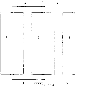
The schematic representation of the rotor platform of aerodynamic force is
presented in
Fig. 1. The basis of the construction is the rotor unit of identical
symmetrical coplanar central
and lateral rotors with load-bearing elements of logarithmic spiral profile,
the prototype thereof
being a marine rotary wind-powered propulsion - BY Ns 8234.
The rotation longitudinal axis 1 of the central rotor 2 is fixed in the
platform frame 3,
whereas the longitudinal axes of the lateral rotors 4 are rigidly tied by
cross-members 5, with
the centers of the cross-members via the bearing units coupled with the fixed
rotation axis of the
central rotor, which allows the firmly inter-tied lateral rotors to repeatedly
take a symmetrical
position in a single plane as per the central rotor.
It is also known that air flow flowing around the rotating body causes
circulation of the air
flow around its contour, the velocity thereof is summed up with the velocity
of the flow when
they are co-directional (4, pages 100-105), which imparts additional kinetic
energy to the flow.
The essence of the invention consists in using the flow with additional
velocity to act on
the consecutive rotor.
The method of generating aerodynamic force by the rotor platform, aerodynamic
force
being a sum of aerodynamic forces generated by each platform rotor, is shown
in Fig. 2.
The air flow with initial velocity Vi falls on the first rotor and sets it to
rotation at the
velocity V1R. Summation of the rotation velocity and flow velocity results in
the flow velocity
that substantially exceeds its initial value
V1S = V1 + V1R.
The flow further falls on the consecutive rotor at the velocity V1S, sets it
to rotation at the
velocity V2R, summation of velocities results in the velocity V2S that renders
its effect on the
consequent rotor, whereby fully repeating the previous cycle.

CA 02715952 2010-09-29
3
Thus, the value of aerodynamic force generated by the rotor platform according
to Kutta-
Joukowski theorem is expressed as follows:
Y=CvP(Vr2 +Vis2 +V2s2)S,
2 2
References:
1. The Great Soviet Encyclopedia, 3rd edition., vol. 2.
2. The Great Soviet Encyclopedia, 3d edition., vol. 13.
3. The Great Soviet Encyclopedia, 3rd edition., vol. 20.
4. Prandtle L., Fluid Mechanics. M., 1951.
5. Merkoulov V.I. Hydrostatics, Known and Unknown, M.,1989
6. Patent BY No. 8234.
Representative Drawing
A single figure which represents the drawing illustrating the invention.
Administrative Status

2024-08-01:As part of the Next Generation Patents (NGP) transition, the Canadian Patents Database (CPD) now contains a more detailed Event History, which replicates the Event Log of our new back-office solution.

Please note that "Inactive:" events refers to events no longer in use in our new back-office solution.

For a clearer understanding of the status of the application/patent presented on this page, the site Disclaimer , as well as the definitions for Patent , Event History , Maintenance Fee  and Payment History  should be consulted.

Event History

Description Date
Application Not Reinstated by Deadline 2013-10-01
Time Limit for Reversal Expired 2013-10-01
Deemed Abandoned - Failure to Respond to Maintenance Fee Notice 2012-10-01
Application Published (Open to Public Inspection) 2011-04-02
Inactive: Cover page published 2011-04-01
Inactive: IPC assigned 2010-11-08
Inactive: First IPC assigned 2010-11-08
Inactive: Applicant deleted 2010-10-21
Filing Requirements Determined Compliant 2010-10-21
Inactive: Filing certificate - No RFE (English) 2010-10-21
Inactive: Inventor deleted 2010-10-21
Inactive: Applicant deleted 2010-10-21
Application Received - Regular National 2010-10-20

Abandonment History

Abandonment Date Reason Reinstatement Date
2012-10-01

Fee History

Fee Type Anniversary Year Due Date Paid Date
Application fee - standard 2010-09-29
Owners on Record

Note: Records showing the ownership history in alphabetical order.

Current Owners on Record
VYACHESLAV STEPANOVICH KLIMOV
OLEG VYACHESLAVOVICH KLIMOV
Past Owners on Record
None
Past Owners that do not appear in the "Owners on Record" listing will appear in other documentation within the application.
Documents

To view selected files, please enter reCAPTCHA code :


To view images, click a link in the Document Description column. To download the documents, select one or more checkboxes in the first column and then click the "Download Selected in PDF format (Zip Archive)" or the "Download Selected as Single PDF" button.

List of published and non-published patent-specific documents on the CPD .

If you have any difficulty accessing content, you can call the Client Service Centre at 1-866-997-1936 or send them an e-mail at CIPO Client Service Centre.


Document
Description 
Date
(yyyy-mm-dd) 
Number of pages   Size of Image (KB) 
Cover Page 2011-03-17 2 40
Description 2010-09-29 3 111
Claims 2010-09-29 1 24
Abstract 2010-09-29 1 16
Drawings 2010-09-29 2 20
Representative drawing 2011-03-17 1 5
Filing Certificate (English) 2010-10-21 1 166
Reminder of maintenance fee due 2012-05-30 1 110
Courtesy - Abandonment Letter (Maintenance Fee) 2012-11-26 1 173