Language selection

Search

Patent 2716054 Summary

Third-party information liability

Some of the information on this Web page has been provided by external sources. The Government of Canada is not responsible for the accuracy, reliability or currency of the information supplied by external sources. Users wishing to rely upon this information should consult directly with the source of the information. Content provided by external sources is not subject to official languages, privacy and accessibility requirements.

Claims and Abstract availability

Any discrepancies in the text and image of the Claims and Abstract are due to differing posting times. Text of the Claims and Abstract are posted:

  • At the time the application is open to public inspection;
  • At the time of issue of the patent (grant).
(12) Patent Application: (11) CA 2716054
(54) English Title: CIRCULATING FLUIDIZED BED (CFB) WITH IN-FURNACE SECONDARY AIR NOZZLES
(54) French Title: LIT DE CIRCULATION FLUIDISE AVEC BUSES D'AIR SECONDAIRE DANS UN FOUR
Status: Deemed Abandoned and Beyond the Period of Reinstatement - Pending Response to Notice of Disregarded Communication
Bibliographic Data
(51) International Patent Classification (IPC):
  • F22B 07/00 (2006.01)
  • F23C 10/00 (2006.01)
(72) Inventors :
  • MARYAMCHIK, MIKHAIL (United States of America)
  • ALEXANDER, KIPLIN C. (United States of America)
  • GODDEN, MARK C. (United States of America)
  • KRAFT, DAVID L. (United States of America)
(73) Owners :
  • BABCOCK & WILCOX POWER GENERATION GROUP, INC.
(71) Applicants :
  • BABCOCK & WILCOX POWER GENERATION GROUP, INC. (United States of America)
(74) Agent: SMART & BIGGAR LP
(74) Associate agent:
(45) Issued:
(22) Filed Date: 2010-09-28
(41) Open to Public Inspection: 2011-03-30
Examination requested: 2015-09-25
Availability of licence: N/A
Dedicated to the Public: N/A
(25) Language of filing: English

Patent Cooperation Treaty (PCT): No

(30) Application Priority Data:
Application No. Country/Territory Date
12/571,279 (United States of America) 2009-09-30

Abstracts

English Abstract


A circulating fluidized bed (CFB) boiler includes a reaction chamber, where a
bubbling fluidized bed (BFB) is contained within an enclosure within the lower
portion of
the reaction chamber and contains an in-bed heat exchanger (IBHX) that
occupies part
of the reaction chamber floor. A plurality of in-bed secondary air nozzles
comprise a
plurality of tubes which are grouped together and run across the width of the
BFB
between the BFB enclosure wall and an outside wall of the CFB. The nozzles are
positioned to prevent the deflection of solids falling onto the BFB from the
CFB by the
secondary air jets while avoiding a complicated structure that would interfere
with gas
and/or solids movement in the furnace. The nozzles' exit openings are flush,
or almost
flush, with the BFB enclosure wall.


Claims

Note: Claims are shown in the official language in which they were submitted.

-6-
CLAIMS
What is claimed is:
1. A circulating fluidized bed (CFB) boiler comprising:
a CFB reaction chamber having side walls and a grid defining a floor at a
lower end of the CFB reaction chamber for providing fluidizing gas into the
CFB reaction
chamber;
a bubbling fluidized bed (BFB) located within a lower portion of the CFB
reaction chamber and being bound by outer wall(s) of the CFB reaction chamber,
the
floor of the CFB reaction chamber and enclosure wall(s) formed by cooled tubes
that
extend upward from the floor of the CFB to the height of the BFB;
at least one controllable in-bed heat exchanger (IBHX), the IBHX
comprising a heating surface and occupying part of the CFB reaction chamber
floor and
being surrounded by the enclosure walls of the BFB; and
at least one in-furnace secondary air nozzle formed by the cooled tubes of
the BFB enclosure wall that are formed into at least one group that extends
from the top
of the BFB enclosure wall across the width of the BFB until reaching the outer
wall of
the CFB.
2. The CFB boiler according to claim 1, wherein when the tubes forming the
at least one in-furnace secondary air nozzle reach the outer wall of the CFB,
the tubes
become part of the outer wall.
3. The CFB boiler according to claim 1, wherein the exit opening of the least
one in-furnace secondary air nozzle is flush, or almost flush, with the
enclosure wall of
the BFB.
4. The CFB boiler according to claim 1, wherein the tubes comprising the
BFB enclosure wall are covered with a protective layer.

-7-
5. The CFB boiler according to claim 4, wherein the protective layer is
formed by a refractory held by studs welded to the tubes.
6. The CFB boiler according to claim 1, wherein the tubes forming the in-
furnace secondary air nozzles are covered with a protective layer.
7. The CFB boiler according to claim 6, wherein the protective layer is
formed by a refractory held by studs welded to the tubes.

Description

Note: Descriptions are shown in the official language in which they were submitted.


CA 02716054 2010-09-28
-1-
CIRCULATING FLUIDIZED BED (CFB) WITH
IN-FURNACE SECONDARY AIR NOZZLES
FIELD AND BACKGROUND OF THE INVENTION
1. Field of the Invention
[0001] The present invention relates generally to the field of circulating
fluidized
bed (CFB) reactors or boilers such as those used in industrial or electric
power
generation facilities and, in particular, to in-furnace secondary air nozzles
designed to
prevent deflection of solids falling onto a bubbling fluidized bed (BFB) from
the CFB by
secondary air jets.
2. Description of the Related Art
[0002] United Sates Patent No. 6,543,905 to Belin et al. describes a CFB
boiler
with controllable in-bed heat exchanger (IBHX). The boiler comprises a CFB
reaction
chamber as well as a BFB heat exchanger located inside the reaction chamber.
Heat
transfer in the heat exchanger is controlled by means of controlling the rate
of solids
discharge from the lower part of the BFB into the reaction chamber. The
overall heat
transfer capacity of the IBHX depends on the solids downflow on the top of the
bubbling
bed in the IBHX from the CFB furnace. A higher downflow rate results in a
higher heat
transfer capacity. Secondary air is typically supplied to a CFB furnace via
nozzles
located at the front and rear furnace walls. The nozzles are located outside
the furnace
enclosure and their exit openings are flush with those walls. Because the IBHX
is
located adjacent to the wall(s) containing the nozzles, jets from the nozzles
will deflect
part of the solids downflow from the IBHX thus reducing its heat transfer
capacity.
[0003] United States Patent No. 5,836,257 to Belin et al. describes a CFB
furnace with an integral secondary air plenum. Such a plenum allows placing
secondary air nozzles inside the furnace thus preventing interference of their
jets with
the solids downflow to the IBHX. However, the supporting structure and/or air
supply
means of the plenum may interfere with the gas and/or solids movement in the
furnace,

CA 02716054 2010-09-28
-l-
and accommodating nozzles of the size sufficient to allow adequate jet
penetration into
a large CFB requires plenum which is larger than desirable.
SUMMARY OF THE INVENTION
[0004] The present invention prevents deflection of the solids falling onto
the BFB
from the CFB by secondary air jets while avoiding a complicated structure that
would
interfere with the gas and/or solids movement in the furnace.
[0005] Accordingly, one aspect of the present invention is drawn to a
circulating
fluidized bed (CFB) boiler comprising: a CFB reaction chamber having side
walls and a
grid defining a floor at a lower end of the CFB reaction chamber for providing
fluidizing
gas into the CFB reaction chamber; a bubbling fluidized bed (BFB) located
within a
lower portion.of the CFB reaction chamber and being bound by outer wall(s) of
the CFB
reaction chamber, the floor of the CFB reaction chamber and enclosure wall(s)
formed
by cooled tubes that extend upward from the floor of the CFB to the height of
the BFB;
at least one controllable in-bed heat exchanger (IBHX), the IBHX comprising a
heating
surface and occupying part of the CFB reaction chamber floor and being
surrounded by
the enclosure walls of the BFB; and at least one in-furnace secondary air
nozzle formed
by the cooled tubes of the BFB enclosure wall that are formed into at least
one group
that extends from the top of the BFB enclosure wall across the width of the
BFB until
reaching the outer wall of the CFB.
[0006] The tubes forming the at least one in-furnace secondary air nozzle may
become part of the outer wall when they reach the outer wall of the CFB.
Additionally,
the exit opening of the least one in-furnace secondary air nozzle is flush, or
almost
flush, with the enclosure wall of the BFB.
[0007] The various features of novelty which characterize the invention are
pointed out with particularity in the claims annexed to and forming part of
this
disclosure. For a better understanding of the invention, its operating
advantages and
specific benefits attained by its uses, reference is made to the accompanying
drawings
and descriptive matter in which exemplary embodiments of the invention are
illustrated.

CA 02716054 2010-09-28
-3-
BRIEF DESCRIPTION OF THE DRAWINGS
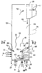
[0008] Fig. 1 is a sectional side elevational view of a CFB boiler according
to the
invention illustrating the secondary, air nozzles;
[0009] Fig. 2 is a sectional plan view of the CFB boiler of Fig. 1, viewed in
the
direction of arrows 2-2 of Fig. 1;
[0010] Fig. 3 is a schematic perspective view of the BFB enclosure, where
tubes
forming the in-furnace secondary air nozzles are represented as single
lines;
[0011] Fig. 4 is a sectional side elevational view of a CFB boiler according
to
another embodiment of the invention; and
[0012] Fig. 5 is a sectional plan view of the CFB boiler of Fig. 4, viewed in
the
direction of arrows 5-5 of Fig. 4.
DESCRIPTION OF THE INVENTION
[0013] The present invention relates generally to the field of circulating
fluidized
bed (CFB) reactors or boilers such as those used in industrial or electric
power
generation facilities and, in particular, to 'in-furnace secondary air nozzles
designed to
prevent the deflection of solids falling into the BFB from the CFB by
secondary air jets.
[0014] As used herein, the term CFB boiler will be used to refer to CFB
reactors
or combustors wherein a combustion process takes place. While the present
invention
is directed particularly to boilers or steam generators which employ CFB
combustors as
the means by which the heat is produced, it is understood that the present
invention can
readily be employed in a different kind of CFB reactor. For example, the
invention could
be applied in a reactor that is employed for chemical reactions other than a
combustion
process, or where a gas/solids mixture from a combustion process occurring
elsewhere
is provided to the reactor for further processing.
[0015] Referring now to the drawings, wherein like reference numerals
designate
the same or functionally similar elements throughout the several drawings and
to Fig. 1
in particular, a sectional side elevational view of a CFB furnace 1 is shown
comprising
walls 2 and an IBHX 3 immersed in a BFB 4. The CFB is predominantly comprised
of

CA 02716054 2010-09-28
-4-
solids made up of the ash from the combustion of the fuel 5, sulfated sorbent
6 and, in
some cases, external inert material 7 fed through at least one of the walls 2
and
fluidized by the primary air 8 supplied through a distribution grid 9. Some
solids are
entrained by gases resulting from the fuel combustion and move upward 15
eventually
reaching a particle separator 16 at the furnace exit. While some of the solids
17 pass
the separator, the bulk of them 18 are captured and recycled back to the
furnace.
Those solids along with others 19, falling out of the upflow solids stream 15,
feed the
BFB 4 that is being fluidized by the fluidizing medium 25 fed through a
distribution grid
26. Means for removing solids from CFB and BFB (27 and 28 respectively) are
provided in the pertinent areas of the furnace floor.
[0016] The BFB is separated from the CFB by an enclosure 30. Rate of solids
recycle 35 back to the CFB through a valve 40 is controlled by controlling
streams of
fluidizing medium 45 and 46. The enclosure is made of tubes 50 that are
typically
cooled by water or steam. The tubes: are usually protected from the erosion
and/or
corrosion by a protective layer, commonly formed by a refractory held by studs
welded
to the tubes. The tubes forming the enclosure extend upward to the elevation
allowing
the required BFB 4 height within the CFB furnace 1. Above the required height,
the
tubes 50 group into forming secondary air nozzles 55. Air 60 fed to these
nozzles is
injected into the CFB beyond the BFB 4, thus its jets 65 do not deflect
streams of solids
18 and 19 from falling onto the BFB 4. Grouping the tubes 50 allows forming
the
openings 70 through which the solids streams 18 and 19 fall onto the BFB 4.
After
reaching the wall 2b, the tubes 50 can become part of this wall. Secondary air
nozzles
75 on the opposite wall 2d are located externally to the CFB furnace 1. Since
no IBHX
is placed below the nozzles 75, their jets 80 do not cause any undesired
effect.
[0017] Fig. 3 illustrates one possible construction of the in-furnace
secondary air
nozzles 55 formed by tubes 50. In Fig. 3, the tubes 50 forming the in-furnace
secondary air nozzles 55 are schematically represented as single lines.
[0018] In an alternative embodiment, illustrated in Figs. 4 and 5, BFB 4 with
immersed IBHX 3 is located on both of opposite furnace walls 2b and 2d. Tubes
50 of
enclosure 30 on both sides of the furnace group to form secondary air nozzles
55. In

CA 02716054 2010-09-28
-5-
order to feed fuel, limestone and other solids streams directly into the CFB,
the BFB on
at least one furnace wall (the 2d wall in this embodiment of Figs. 4 and 5) is
broken into
several compartments 80. Each compartment 80 is formed by a furnace wall 2d,
enclosure 30 and two side walls 85 (or one side wall 85 and a furnace wall 2a
or 2c).
The compartments are separated from each other by gaps 90 where the fuel,
limestone,
etc. is fed.
[0019] While specific embodiments of the present invention have been shown
and described in detail to illustrate the application and principles of the
invention, it will
be understood that it is not intended that the present invention be limited
thereto and
that the invention may be embodied otherwise without departing from such
principles.
In some embodiments of the invention, certain features of the invention may
sometimes
be used to advantage without a corresponding use of the other features.
Accordingly,
all such changes and embodiments properly fall within the scope of the
following claims.

Representative Drawing
A single figure which represents the drawing illustrating the invention.
Administrative Status

2024-08-01:As part of the Next Generation Patents (NGP) transition, the Canadian Patents Database (CPD) now contains a more detailed Event History, which replicates the Event Log of our new back-office solution.

Please note that "Inactive:" events refers to events no longer in use in our new back-office solution.

For a clearer understanding of the status of the application/patent presented on this page, the site Disclaimer , as well as the definitions for Patent , Event History , Maintenance Fee  and Payment History  should be consulted.

Event History

Description Date
Inactive: Dead - No reply to s.30(2) Rules requisition 2017-12-28
Application Not Reinstated by Deadline 2017-12-28
Deemed Abandoned - Failure to Respond to Maintenance Fee Notice 2017-09-28
Inactive: Abandoned - No reply to s.30(2) Rules requisition 2016-12-28
Inactive: S.30(2) Rules - Examiner requisition 2016-06-27
Inactive: Report - No QC 2016-06-23
Letter Sent 2015-10-16
Amendment Received - Voluntary Amendment 2015-09-25
Request for Examination Received 2015-09-25
All Requirements for Examination Determined Compliant 2015-09-25
Request for Examination Requirements Determined Compliant 2015-09-25
Application Published (Open to Public Inspection) 2011-03-30
Inactive: Cover page published 2011-03-29
Inactive: Reply to s.37 Rules - Non-PCT 2011-01-25
Inactive: IPC assigned 2010-12-15
Inactive: First IPC assigned 2010-12-15
Inactive: IPC assigned 2010-12-15
Inactive: Request under s.37 Rules - Non-PCT 2010-10-26
Inactive: Filing certificate - No RFE (English) 2010-10-21
Application Received - Regular National 2010-10-21

Abandonment History

Abandonment Date Reason Reinstatement Date
2017-09-28

Maintenance Fee

The last payment was received on 2016-09-01

Note : If the full payment has not been received on or before the date indicated, a further fee may be required which may be one of the following

  • the reinstatement fee;
  • the late payment fee; or
  • additional fee to reverse deemed expiry.

Patent fees are adjusted on the 1st of January every year. The amounts above are the current amounts if received by December 31 of the current year.
Please refer to the CIPO Patent Fees web page to see all current fee amounts.

Fee History

Fee Type Anniversary Year Due Date Paid Date
Application fee - standard 2010-09-28
MF (application, 2nd anniv.) - standard 02 2012-09-28 2012-08-31
MF (application, 3rd anniv.) - standard 03 2013-09-30 2013-09-03
MF (application, 4th anniv.) - standard 04 2014-09-29 2014-09-05
MF (application, 5th anniv.) - standard 05 2015-09-28 2015-09-03
Request for examination - standard 2015-09-25
MF (application, 6th anniv.) - standard 06 2016-09-28 2016-09-01
Owners on Record

Note: Records showing the ownership history in alphabetical order.

Current Owners on Record
BABCOCK & WILCOX POWER GENERATION GROUP, INC.
Past Owners on Record
DAVID L. KRAFT
KIPLIN C. ALEXANDER
MARK C. GODDEN
MIKHAIL MARYAMCHIK
Past Owners that do not appear in the "Owners on Record" listing will appear in other documentation within the application.
Documents

To view selected files, please enter reCAPTCHA code :


To view images, click a link in the Document Description column. To download the documents, select one or more checkboxes in the first column and then click the "Download Selected in PDF format (Zip Archive)" or the "Download Selected as Single PDF" button.

List of published and non-published patent-specific documents on the CPD .

If you have any difficulty accessing content, you can call the Client Service Centre at 1-866-997-1936 or send them an e-mail at CIPO Client Service Centre.


Document
Description 
Date
(yyyy-mm-dd) 
Number of pages   Size of Image (KB) 
Description 2010-09-27 5 222
Claims 2010-09-27 2 45
Drawings 2010-09-27 3 54
Abstract 2010-09-27 1 21
Representative drawing 2011-03-01 1 5
Filing Certificate (English) 2010-10-20 1 166
Reminder of maintenance fee due 2012-05-28 1 110
Courtesy - Abandonment Letter (Maintenance Fee) 2017-11-08 1 174
Reminder - Request for Examination 2015-05-31 1 118
Acknowledgement of Request for Examination 2015-10-15 1 174
Courtesy - Abandonment Letter (R30(2)) 2017-02-07 1 164
Correspondence 2010-10-20 1 28
Correspondence 2011-01-24 2 65
Request for examination 2015-09-24 3 78
Examiner Requisition 2016-06-26 3 202