Language selection

Search

Patent 2716171 Summary

Third-party information liability

Some of the information on this Web page has been provided by external sources. The Government of Canada is not responsible for the accuracy, reliability or currency of the information supplied by external sources. Users wishing to rely upon this information should consult directly with the source of the information. Content provided by external sources is not subject to official languages, privacy and accessibility requirements.

Claims and Abstract availability

Any discrepancies in the text and image of the Claims and Abstract are due to differing posting times. Text of the Claims and Abstract are posted:

  • At the time the application is open to public inspection;
  • At the time of issue of the patent (grant).
(12) Patent Application: (11) CA 2716171
(54) English Title: PORTABLE FOLDING DISPLAY RACK
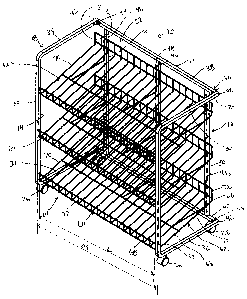
(54) French Title: PRESENTOIR PORTATIF REPLIABLE
Status: Deemed Abandoned and Beyond the Period of Reinstatement - Pending Response to Notice of Disregarded Communication
Bibliographic Data
(51) International Patent Classification (IPC):
  • A47F 5/13 (2006.01)
  • A47B 47/02 (2006.01)
  • A47F 5/01 (2006.01)
  • A47F 5/16 (2006.01)
(72) Inventors :
  • SALZSTEIN, SCOTT L. (United States of America)
(73) Owners :
  • HANDI-FOIL CORPORATION
(71) Applicants :
  • HANDI-FOIL CORPORATION (United States of America)
(74) Agent: MCCARTHY TETRAULT LLP
(74) Associate agent:
(45) Issued:
(22) Filed Date: 2010-09-30
(41) Open to Public Inspection: 2011-05-24
Availability of licence: N/A
Dedicated to the Public: N/A
(25) Language of filing: English

Patent Cooperation Treaty (PCT): No

(30) Application Priority Data:
Application No. Country/Territory Date
12/624,624 (United States of America) 2009-11-24

Abstracts

English Abstract


A portable display rack is provided with a frame having a front side, a rear
side, a left
side, a right side, a top side, and a bottom side. A plurality of shelves
positioned between the
left and rights sides and extending from the rear side towards the front side.
Each shelf has a
width defined such that the front portion extends between first and second
vertical posts
defined by the front side. The left and right side of the frame is pivotally
hinged to the rear
side, such that when the shelves are removed, the left and right sides of the
frame are capable
of being folded along the pivotally hinges against the rear side of the frame.


Claims

Note: Claims are shown in the official language in which they were submitted.

We Claim
1. A portable display rack, comprising:
a frame having a front side, a rear side, a left side, a right side, a top
side, and a bottom
side, wherein:
i) the front side of the frame being defined by a first vertical post and a
second vertical post separated from the first vertical post by a distance,
permitting
said front side of said frame to be substantially open,
ii) the left and right sides of the frame each being defined by first and
second
horizontal side posts extending from both ends of the first and second
vertical posts
towards the rear side of the frame,
iii) the rear side of the frame being defined by first and second horizontal
rear posts extending along the rear side and being separately connect by
pivotally
attachments to ends defined by the first and second side posts, the rear side
of the
frame further defined by having three vertical rear posts connected between
the
first and second horizontal rear posts, each of the three vertical rear posts
having
spaced apart apertures;
a plurality of shelves positioned between the left and rights sides and
extending from
the rear side towards the front side, each shelf, of the plurality of shelves,
having at least a flat
bottom and rear and front portions with an upwardly turned retention end
positioned along
the front portion, and further having a width defined such that the front
portion extends
between the first and second vertical posts defined by the front side, each
shelf further being
8

angled such that its rear portion is positioned at a higher vertical height
then the front portion;
and
each shelf, of the plurality of shelves, includes three braces separately
securing the flat
bottom of the shelf to the three vertical posts,
whereby, when the shelves are removed, the left and right sides of the frame
are
capable of being folded along the pivotally attachments for positioning
against the rear side of
the frame.
2. The portable display rack of Claim 1, wherein the first horizontal side
posts extend about
a top portion of the left and right sides of the frame to further define the
top side of the frame,
and wherein the second horizontal side posts extend about a bottom portion of
the left and
right sides of the frame to further define the bottom side of the frame.
3. The portable display rack of Claim 2 further comprising a plurality of
casters secured to
an underside of the bottom side of the frame.
4. The rack display of Claim 1, wherein the pivotally attachment is
accomplished by having
separate folding brackets connecting each end of the first and second
horizontal rear posts to
ends of the first and second side posts.
5. The rack display of Claim 1, wherein the three vertical rear posts is
further defined as a
pair of outer posts separated by a distance therebetween and a middle post
positioned
9

between the two outer posts, the pair of outer posts being further positioned
inwardly along
the rear side by a distance from the pivotal attachment.
6. The rack display of Claim 1, wherein each of the braces include an
outstanding arm
section secured to the flat bottom and an upstanding arm section that has a
back side
positioned against the rear vertical post and includes a hook extending from
the upstanding
arm section, the hook being received in the apertures defined along the three
vertical rear
posts.
7. The rack display of Claim 1, wherein each shelf, of the plurality of
shelves further
includes an upwardly turned retention end positioned along the back portion.
8. A portable display rack, comprising:
a frame having a front side, a rear side, a left side, a right side, a top
side, and a bottom
side, wherein:
i) the front side of the frame being defined by a first vertical post and a
second vertical post separated from the first vertical post by a distance,
permitting
said front side of said frame to be substantially open,
ii) the left and right sides of the frame each being defined by first and
second
horizontal side posts extending from both ends of the first and second
vertical posts
towards the rear side of the frame,
10

iii) the rear side of the frame being defined by first and second horizontal
rear posts extending along the rear side and being separately connect by
pivotally
attachments to ends defined by the first and second side posts, the rear side
of the
frame further defined by having three vertical rear posts connected between
the
first and second horizontal rear posts, each of the three vertical rear posts
having
spaced apart apertures, and
wherein the three vertical rear posts is further defined as a pair of outer
posts separated by a distance therebetween and a middle post positioned
between
the two outer posts, the pair of outer posts being further positioned inwardly
along
the rear side by a distance from the pivotal attachment;
a plurality of shelves positioned between the left and rights sides and
extending from
the rear side towards the front side, each shelf, of the plurality of shelves,
having at least a flat
bottom and rear and front portions with an upwardly turned retention end
positioned along
the front portion, and further having a width defined such that the front
portion extends
between the first and second vertical posts defined by the front side, each
shelf further being
angled such that its rear portion is positioned at a higher vertical height
then the front portion,
each shelf, of the plurality of shelves further includes an upwardly turned
retention end
positioned along the back portion; and
each shelf, of the plurality of shelves, includes three braces separately
securing the flat
bottom of the shelf to the three vertical posts,
11

whereby, when the shelves are removed, the left and right sides of the frame
are
capable of being folded along the pivotally attachments for positioning
against the rear side of
the frame.
9. The portable display rack of Claim 8, wherein the first horizontal side
posts extend about
a top portion of the left and right sides of the frame to further define the
top side of the frame,
and wherein the second horizontal side posts extend about a bottom portion of
the left and
right sides of the frame to further define the bottom side of the frame.
10. The portable display rack of Claim 9 further comprising a plurality of
casters secured to
an underside of the bottom side of the frame.
11. The rack display of Claim 8, wherein the pivotally attachment is
accomplished by having
separate folding brackets connecting each end of the first and second
horizontal rear posts to
ends of the first and second side posts.
12. The rack display of Claim 8, wherein each of the braces include an
outstanding arm
section secured to the flat bottom and an upstanding arm section that has a
back side
positioned against the rear vertical post and includes a hook extending from
the upstanding
arm section, the hook being received in the apertures defined along the three
vertical rear
posts.
12

Description

Note: Descriptions are shown in the official language in which they were submitted.


CA 02716171 2010-09-30
PORTABLE FOLDING DISPLAY RACK
Field of the Invention
[01] The present invention relates to merchandise display racks, and more
particularly to a
portable folding display rack which is easy to assemble and adapted to display
products.
Background of the Invention
[02] Merchandise display racks are used to hold and display a wide variety of
products.
Often times the display racks will include casters or the like in order to
provide the flexibility to
move the display racks anywhere in a store. Portable display racks which are
provided by a
manufacturer are usually adapted for use with a particular type or brand of
merchandise.
These portable display racks are often pre-assembled or once assembled only
capable of being
moved by the casters. Thus there is .an advantage to having the display rack
easily foldable
such that the there is little assembly time or if needed can be easily folded
and moved to
another store or location within a store that is inaccessible or difficult to
place because of the
casters. In addition, close review of these and other prior art references
finds that the shelf or
basket are always leveled with or held relatively even with the bracket.
Therefore, there is also
an advantage to have the display rack assembled with slanted shelving to
support the display of
specialized goods.
1

CA 02716171 2010-09-30
Summary of the Invention
[03] In accordance with the present invention there is provided in one
embodiment a
portable display rack. The display rack is defined by a frame having a front
side, a rear side, a
left side, a right side, a top side, and a bottom side and a plurality of
shelves. The front side of
the frame has a first vertical post and a second vertical post separated from
the first vertical
post by a distance, permitting the front side of the frame to be substantially
open. The left and
right sides of the frame each have first and second horizontal side posts
extending from both
ends of the first and second vertical posts towards the rear side of the
frame. The rear side of
the frame has first and second horizontal rear posts extending along the rear
side and being
separately connect by pivotally attachments to ends defined by the first and
second side posts.
The rear side of the frame further has three vertical rear posts connected
between the first and
second horizontal rear posts. Each of the three vertical rear posts have
spaced apart apertures.
[04] The plurality of shelves are positioned between the left and rights sides
and extend from
the rear side towards the front side of the frame. Each shelf has at least a
flat bottom and rear
and front portions with an upwardly turned retention end positioned along the
front portion.
The shelves each further have a width defined such that the front portion
extends between the
first and second vertical posts defined by the front side of the frame. Each
shelf is further
angled such that its rear portion is positioned at a higher vertical height
then the front portion.
[05] Therefore, when the shelves are removed, the left and right sides of the
frame are
capable of being folded along the pivotally attachments for positioning
against the rear side of
the frame.
2

CA 02716171 2010-09-30-
[06) In other embodiment the rack, the top side of the frame may be defined by
having the
first horizontal side posts extend about a top portion of the left and right
sides of the frame,
and wherein the second horizontal side posts extend about a bottom portion of
the left and
right sides of the frame to further define the bottom side of the frame. In
yet other aspects of
the invention, the portable display rack may further include a plurality of
casters secured to an
underside of the bottom side of the frame.
[07] In yet other embodiments, the three vertical rear posts are further
defined as a pair of
outer posts separated by a distance therebetween and a middle post positioned
between the
two outer posts. The pair of outer posts being further positioned inwardly
along the rear side
by a distance from the pivotal attachment.
[08] In yet still other aspects, each of the braces may include an outstanding
arm section
secured to the flat bottom and an upstanding arm section that has a back side
positioned
against the rear vertical post and includes a hook extending from the
upstanding arm section.
The hook being received in the apertures defined along the three vertical rear
posts.
[09] Numerous other advantages and features of the invention will become
readily apparent
from the following detailed description of the invention and the embodiments
thereof, from
the claims, and from the accompanying drawings.
Brief Description of the Drawings
[10] A fuller understanding of the foregoing may be had by reference to the
accompanying
drawings, wherein:
[11] FIG 1 is a perspective view of one embodiment of the present invention;
3

CA 02716171 2010-09-30
[12] FIG 2 is an enlarged view of section 2 from FIG 1;
[13] FIG 3 is a top view of FIG 1;
[14] FIG 4 is a side view of FIG 1; and
[15] FIG 5 is a perspective view of one embodiment of the present invention,
illustrating the
display rack without shelving and in a folded position.
Detailed Description of the Embodiments
[16] While the invention is susceptible to embodiments In many different
forms, there are
shown in the drawings and will be described herein, in detail, the preferred
embodiments of
the present invention. It should be understood, however, that the present
disclosure is to be
considered an exemplification of the principles of the invention and is not
intended to limit the
spirit or scope of the invention and/or claims of the embodiments illustrated.
[17] With reference to FIGS 1-5 there is shown a first embodiment of the
display rack 10.
The display rack 10 may comprise a frame 12 having a front side 14, a rear
side 16, a left side
18, a right side 20, a top side 22, and a bottom side 24. The display rack 10
further comprises a
plurality of shelves 60 (discussed in greater detail below). The rack 10 is
preferably portable
and may comprise a plurality of conventional and commercially available
casters 26 which may
be equipped with releasable locks or brakes (not shown) to selectively prevent
rotation thereof.
[18] The frame 12 may be comprised of a plurality of posts assembled together
to form the
various sides. The front side 14 may include a pair of vertical posts, namely
a first front post 30
and a second front post 32 that are separated from one another by a distance
D1. The front
4

CA 02716171 2010-09-30
side 14 is preferably substantially open so that the merchandise on the
shelves 60 is highly
visible and accessible to the customers.
(19] Extending horizontally from the ends of the two front posts (30 and 32)
towards the rear
side 16 of the frame 10 are first and second side posts 34 and 36,
respectively. The first side
posts 34 extend along the top side 22 of the frame, while the second side
posts 36 extend along
the bottom side 24 of the frame.
[20] The rear side 16 of the frame 10 includes a pair of horizontal posts, a
top rear horizontal
post 38 and a bottom rear'horizontal post 40. The pair of horizontal posts are
pivotally
attached 44 at their side ends 54 to the rear ends 42 of the first and second
side posts 34 and
36. The pivotally attachment means 44 used to secure the rear ends 42 of the
side posts 34, 36
to the side ends 54 of the rear posts 38 and 40 is an inside hinge bracket 56,
which permits the
right and left sides 16, 18 of the frame 10 to fold into the rear side 16 of
the frame.
[21] Three vertical rear posts 46 (a middle rear post 48 and a pair of outer
posts 50) extend
between the pair of horizontal posts 38 and 40. The pair of outer posts 50 are
positioned
inwardly along the rear side 16 by a distance D2 from the pivotal attachment
44 of the ends.
The inward position of the outer posts 50 help stabilize the assembled frame.
Each of the three
vertical rear posts 45 include apertures 52 aligned along the same vertical
height, The =
apertures 52 are sized to receive an end of the brace 74 used for the shelf 60
(discussed in
further detail below).
[22] Each shelf 60 used on the display rack 10 is formed of a generally U-
shaped outer frame
62 inasmuch as the outer frame 62 has a flat bottom 64 with a back portion 66
and a front
portion 68 and two side portions 70 to define a width W and length L of the
shelf. The back

CA 02716171 2010-09-30
portion 66 and front portion 68 include upwardly turned retention ends 72 to
form a retainer
for articles positioned on the shelf 60. The outer frame 62 is generally
fabricated from
relatively heavy gauge wire.
[23] The back portion 66 is at a higher position then the front portion 68
such that the flat
bottom 64 is angled. The length L of the shelf between the two side portions
70 is defined to
be smaller than the distance D1 defined by the two front posts 30 and 32. In
addition, the
width W of the shelf between the front and back portions 66 and 68 Is defined
such that the
front portion 68 is positioned between the two front posts 30 and 32. Each
shelf is supported
by braces 74, preferably three, corresponding to the three rear vertical
posts. The braces 74
are L shaped, having an outstanding arm section 76 secured to the bottom of
the flat bottom
64, and an upstanding arm section 78 that rests against the rear vertical
posts 46. Extending
from an end of the upstanding arm section 78 is a flange or hook 80 that
inserts into the
aperture 52 and which removably secures the shelf 60 to the frame (or to the
rear vertical
posts).
[24] By removing the shelves 60, the frame 10 can fold and be easily
transported or moved.
Folding the frame 10 is done at the hinging means 44 permitting the left 18
and right sides 20 of
the frame 10 to fold towards and against the rear side 16, shown in FIG 5.
[25] From the foregoing and as mentioned above, it will be observed that
numerous
variations and modifications may be effected without departing from the spirit
and scope of the
novel concept of the invention. It is to be understood that no limitation with
respect to the
specific methods and apparatus illustrated herein is intended or should be
inferred. It is, of
6

CA 02716171 2010-09-30
course, intended to cover by the appended claims all such modifications as.
fall within the scope I'
of the claims.
i 1.
is
7

Representative Drawing
A single figure which represents the drawing illustrating the invention.
Administrative Status

2024-08-01:As part of the Next Generation Patents (NGP) transition, the Canadian Patents Database (CPD) now contains a more detailed Event History, which replicates the Event Log of our new back-office solution.

Please note that "Inactive:" events refers to events no longer in use in our new back-office solution.

For a clearer understanding of the status of the application/patent presented on this page, the site Disclaimer , as well as the definitions for Patent , Event History , Maintenance Fee  and Payment History  should be consulted.

Event History

Description Date
Application Not Reinstated by Deadline 2014-09-30
Time Limit for Reversal Expired 2014-09-30
Deemed Abandoned - Failure to Respond to Maintenance Fee Notice 2013-09-30
Application Published (Open to Public Inspection) 2011-05-24
Inactive: Cover page published 2011-05-23
Inactive: IPC assigned 2010-11-10
Inactive: First IPC assigned 2010-11-10
Filing Requirements Determined Compliant 2010-10-25
Letter Sent 2010-10-25
Inactive: Filing certificate - No RFE (English) 2010-10-25
Application Received - Regular National 2010-10-21
Amendment Received - Voluntary Amendment 2010-09-30

Abandonment History

Abandonment Date Reason Reinstatement Date
2013-09-30

Maintenance Fee

The last payment was received on 2012-09-21

Note : If the full payment has not been received on or before the date indicated, a further fee may be required which may be one of the following

  • the reinstatement fee;
  • the late payment fee; or
  • additional fee to reverse deemed expiry.

Please refer to the CIPO Patent Fees web page to see all current fee amounts.

Fee History

Fee Type Anniversary Year Due Date Paid Date
Application fee - standard 2010-09-30
Registration of a document 2010-09-30
MF (application, 2nd anniv.) - standard 02 2012-10-01 2012-09-21
Owners on Record

Note: Records showing the ownership history in alphabetical order.

Current Owners on Record
HANDI-FOIL CORPORATION
Past Owners on Record
SCOTT L. SALZSTEIN
Past Owners that do not appear in the "Owners on Record" listing will appear in other documentation within the application.
Documents

To view selected files, please enter reCAPTCHA code :


To view images, click a link in the Document Description column. To download the documents, select one or more checkboxes in the first column and then click the "Download Selected in PDF format (Zip Archive)" or the "Download Selected as Single PDF" button.

List of published and non-published patent-specific documents on the CPD .

If you have any difficulty accessing content, you can call the Client Service Centre at 1-866-997-1936 or send them an e-mail at CIPO Client Service Centre.


Document
Description 
Date
(yyyy-mm-dd) 
Number of pages   Size of Image (KB) 
Drawings 2010-09-30 4 109
Description 2010-09-30 7 224
Abstract 2010-09-30 1 16
Claims 2010-09-30 5 151
Representative drawing 2011-04-27 1 27
Cover Page 2011-04-28 2 61
Courtesy - Certificate of registration (related document(s)) 2010-10-25 1 127
Filing Certificate (English) 2010-10-25 1 166
Reminder of maintenance fee due 2012-05-31 1 110
Courtesy - Abandonment Letter (Maintenance Fee) 2013-11-25 1 172
Fees 2012-09-21 1 36