Language selection

Search

Patent 2716233 Summary

Third-party information liability

Some of the information on this Web page has been provided by external sources. The Government of Canada is not responsible for the accuracy, reliability or currency of the information supplied by external sources. Users wishing to rely upon this information should consult directly with the source of the information. Content provided by external sources is not subject to official languages, privacy and accessibility requirements.

Claims and Abstract availability

Any discrepancies in the text and image of the Claims and Abstract are due to differing posting times. Text of the Claims and Abstract are posted:

  • At the time the application is open to public inspection;
  • At the time of issue of the patent (grant).
(12) Patent Application: (11) CA 2716233
(54) English Title: DOWNHOLE MEASUREMENT WHILE DRILLING SYSTEM AND METHOD
(54) French Title: SYSTEME ET PROCEDE DE MESURE AU FOND DU TROU PENDANT LE FORAGE
Status: Deemed Abandoned and Beyond the Period of Reinstatement - Pending Response to Notice of Disregarded Communication
Bibliographic Data
(51) International Patent Classification (IPC):
  • E21B 47/12 (2012.01)
  • E21B 47/04 (2012.01)
  • E21B 47/13 (2012.01)
  • G01V 3/18 (2006.01)
(72) Inventors :
  • ZAEPER, RALF (Germany)
  • KING, MICHAEL W. (United States of America)
(73) Owners :
  • BAKER HUGHES INCORPORATED
(71) Applicants :
  • BAKER HUGHES INCORPORATED (United States of America)
(74) Agent: MARKS & CLERK
(74) Associate agent:
(45) Issued:
(86) PCT Filing Date: 2009-02-19
(87) Open to Public Inspection: 2009-08-27
Examination requested: 2010-08-19
Availability of licence: N/A
Dedicated to the Public: N/A
(25) Language of filing: English

Patent Cooperation Treaty (PCT): Yes
(86) PCT Filing Number: PCT/US2009/034546
(87) International Publication Number: WO 2009105561
(85) National Entry: 2010-08-19

(30) Application Priority Data:
Application No. Country/Territory Date
61/029,676 (United States of America) 2008-02-19

Abstracts

English Abstract


A method of measuring while drilling includes
positioning at least one sensor downhole; and transmitting
sensed data while drilling from the at least one sensor to
sur-face without storing the sensed data downhole and system.


French Abstract

Linvention concerne un procédé de mesure pendant le forage comprenant le positionnement dau moins un capteur au fond du trou et la transmission des données détectées pendant le forage depuis ledit capteur vers la surface sans stocker les données détectées au fond du trou. Linvention concerne également un système associé.

Claims

Note: Claims are shown in the official language in which they were submitted.

CLAIMS
What is claimed is:
1. A method of measuring while drilling, comprising:
positioning at least one sensor downhole; and
transmitting at least about 40 percent of sensed data while drilling from the
at
least one sensor to surface without processing the sensed data downhole.
2. The method of measuring while drilling of claim 1, further comprising
communicatively coupling the at least one sensor to surface via wired pipe.
3. The method of measuring while drilling of claim 1, further comprising
digitally modulating the sensed data with one of phase-shift keying (PSK),
frequency-
shit keying (FSK) and amplitude-shift keying (ASK).
4. The method of measuring while drilling of claim 1, further comprising
digitizing the sensed data.
5. The method of measuring while drilling of claim 1, further comprising
multiplexing a plurality of signals from the sensor(s) to a single analog-to-
digital
converter.
6. The method of measuring while drilling of claim 1, further comprising
multiplexing a plurality of signals from the sensor(s) to a single
communication
medium.
7. A downhole measurement while drilling system comprising:
at least one sensor-sub at a drillstring locatable downhole during a wellbore
operation, the sensor-sub having at least one sensor; and
a communication medium at the drillstring configured to transmit sensed data
between the at least one sensor-sub and a surface processor, the downhole
measurement while drilling system being without downhole processing of at
least 40
percent of the sensed data.

8. The downhole measurement while drilling system of claim 7, further
comprising at least one multiplexer in operable communication with the at
least one
sensor.
9. The downhole measurement while drilling system of claim 7, further
comprising at least one analog-to-digital converter in operable communication
with
the at least one sensor.
10. The downhole measurement while drilling system of claim 7, further
comprising at least one modulator in operable communication with the at least
one
sensor.
11. The downhole measurement while drilling system of claim 7, further
comprising at least one power supply in operable communication with the at
least one
sensor.
12. The downhole measurement while drilling system of claim 7 wherein
the sensed data communicated is at least 50 percent unprocessed.
13. The downhole measurement while drilling system of claim 7 wherein
the sensed data communicated is at least 100 percent unprocessed.
14. The downhole measurement while drilling system of claim 7 wherein
the at least one sensor is a drilling dynamics sensor.
15. The downhole measurement while drilling system of claim 14 wherein
the drilling dynamics sensor is selected from the group consisting of an
acceleration
sensor, a strain sensor, a gyroscope, a gravitational field sensor, a
temperature sensor,
a weight sensor, a torque sensor, a bending-moment sensor, a vibration sensor,
a
rotation sensor, a rate of penetration sensor, and a magnetic field sensor.
16. The downhole measurement while drilling system of claim 7 wherein
the at least one sensor is a formation evaluation sensor.
17. The downhole measurement while drilling system of claim 16 wherein
the formation evaluation sensor is selected from the group consisting of a
pressure
sensor, a temperature sensor, an acoustic sensor, a gravitational field
sensor, a
6

resistivity sensor, a rate of penetration sensor, a magnetic field sensor, an
electrode, a
gamma ray detector, a density sensor, a neutron sensor, an imaging sensor,
NMR,
geophone, hydrophone, a formation sampling, and a dipmeter.
18. A method of measuring while drilling, comprising:
positioning at least one sensor downhole; and
transmitting sensed data while drilling from the at least one sensor to
surface
without processing the sensed data downhole.
7

Description

Note: Descriptions are shown in the official language in which they were submitted.


CA 02716233 2010-08-19
WO 2009/105561 PCT/US2009/034546
DOWNHOLE MEASUREMENT WHILE DRILLING SYSTEM AND
METHOD
Inventor(s) ZAEPER, Ralf & KING, Michael W.
CROSS REFERENCE TO RELATED APPLICATIONS
[0001] This application claims priority to U.S. Provisional Application Number
61/029,676 filed on February 19, 2008, the entire contents of which are
incorporated
herein by reference.
BACKGROUND OF THE INVENTION
[0002] The hydrocarbon recovery industry is always in search of ways to
increase
efficiency of extracting hydrocarbons. Improving an understanding of the
downhole
conditions encountered while drilling is beneficial in this endeavor. As such,
operators are employing more electronics with increasing complexity toward
this
objective. Unfortunately, as the quantity and complexity of electronics
deployed
downhole increases, so does the number of potential failure modes and
instances of
failures. Systems, therefore, that allow fewer, less complex and more durable
electronics to be employed downhole while maintaining the improved
understanding
of the downhole conditions as noted above are desirable in the art.
BRIEF DESCRIPTION OF THE INVENTION
[0003] A method of measuring while drilling includes positioning at least one
sensor
downhole; and transmitting sensed data while drilling from the at least one
sensor to
surface without processing the sensed data downhole.
[0004] A downhole measurement while drilling system includes at least one
sensor-
sub at a drillstring locatable downhole during a wellbore operation, the
sensor-sub
having at least one sensor; and a communication medium at the drillstring
configured
to transmit sensed data between the at least one sensor-sub and a surface
processor,
the downhole measurement while drilling system being without downhole
processing
of at least 40 percent of the sensed data.
1

CA 02716233 2010-08-19
WO 2009/105561 PCT/US2009/034546
BRIEF DESCRIPTION OF THE DRAWINGS
[0005] The following descriptions should not be considered limiting in any
way.
With reference to the accompanying drawings, like elements are numbered alike:
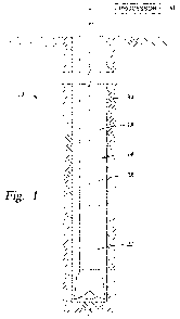
FIG. 1 depicts a schematical view of a downhole measurement while drilling
system disclosed herein.
FIG. 2 is an enlarged view of the sensor-sub portion of the system illustrated
in FIG. 1.
DETAILED DESCRIPTION OF THE INVENTION
[0006] A detailed description of one or more embodiments of the disclosed
apparatus
and method are presented herein by way of exemplification and not limitation
with
reference to the Figures.
[0007] Referring to FIG. 1 and FIG. 2, an embodiment of the downhole
measurement while drilling system 10 disclosed herein is illustrated. The
measurement while drilling system 10 includes, a drillstring 14 having a high
speed
communication channel 18 and at least one sensor-sub 22, with each sensor-sub
22
having at least one sensor 26, and a processor 30 at surface (or other remote
location)
that is communicatively coupled with the at least one sensor-sub 22 and the at
least
one sensor 26 via a communication medium 28 in the drill string 18. The sensor-
sub
22 is positionable downhole within a wellbore 34 during well operations, such
as
drilling, for example. The system 10 communicates, in one embodiment at least
about
40 percent of sensed data from at least one sensor to the processor 30 via the
high
speed channel 18 without being processed downhole. In another embodiment, the
communicated unprocessed data is about 50 percent of the sensed data from the
at
least one sensor and in yet another embodiment 100 percent of the sensed data
is
communicated uphole unprocessed. It should be understood that the term "sensed
data" as used herein means data acquired from the sensor(s) 26. As such, data
that
has been digitized, or compressed, for example, is still considered sensed
data as long
as it originated from the sensor(s) 26.
2

CA 02716233 2010-08-19
WO 2009/105561 PCT/US2009/034546
[0008] The at least one sensor 26 may be any of the following; a pressure
sensor, a
strain sensor, an acceleration sensor, a temperature sensor, an acoustic
sensor, a
gravitational field sensor, a gyroscope, a resistivity sensor, a weight
sensor, a torque
sensor, a bending-moment sensor, a vibration sensor, a rotation sensor, a rate
of
penetration sensor, a magnetic field sensor, NMR, geophone, hydrophone,
formation
sampling, a caliper, an electrode, a gamma ray detector, a density sensor, a
neutron
sensor, a dipmeter, an imaging sensor, and other sensors useful in well
logging and
well drilling. The sensor(s) 26 may output an analog signal, a digital signal
or both an
analog signal and a digital signal.
[0009] Each of the at least one sensor-sub 22, in addition to having at least
one sensor
26 may also include, one or more analog-to-digital converter (ADC) 38, one or
more
multiplexers 42, one or more modulators 46 and one or more power supplies 50.
The
one or more power supplies 50 can be configured to supply power to each of,
the
sensor(s) 26, ADC(s) 38, multiplexer(s) 42 and modulator(s) 46. Some
embodiments
of the invention, however, may not employ a separate power supply 50 as power
may
be supplied from surface via the communication medium 28 in the pipe 18, for
example.
[0010] The ADC(s) 38, if employed, can convert analog signals from the one or
more
sensors 26 (for analog sensors) attached thereto to digital signals prior to
transmission
to surface over the communication medium 28. Transmitting (modulated) digital
signals may be preferred over transmitting analog signals for reasons commonly
known such as, error avoidance, error correction, efficient use of available
bandwidth
and low power requirements, for example.
[0011] The multiplexer(s) 42, if employed, can permit multiple signals, either
analog
or digital, to be transmitted over the single communication medium 28. The
multiplexer(s) 42 also permits the use of a plurality of the sensors 26 while
using a
single or reduced number of ADCs 38, thereby saving the costs and complexity
associated with multiple, parallel operating ADCs 38. Additionally, the
multiplexer(s) 42 can reduce the number and complexity of circuit components
employed downhole, thereby reducing system failures that may have occurred had
the
number and complexity of components not been reduced.
3

CA 02716233 2010-08-19
WO 2009/105561 PCT/US2009/034546
[0012] The modulator(s) 46, if employed, can modulate the signal, whether it
is
analog or digital, to optimize transmission over the communication medium 28
available. The modulator(s) 46 can modulate the signals with a modulating
scheme,
such as phase-shift keying (PSK), frequency-shit keying (FSK) and amplitude-
shift
keying (ASK), for example. A signal from one of the sensor(s) 26 may form a
base-
band signal for the modulation. The processor 30 at surface can distinguish
data from
each of the sensor(s) 26 by channel of transmission, timing sequence,
transmission
pattern or any other recognition scheme employed by the system 10. The
modulator(s) 46, multiplexer(s) 42 and ADC(s) 38 can be used separately or
together
to transmit large amounts of data from the sensors 26 to the processor 30 at
the
surface via the communication medium 28, of the drill pipe 18. The ability to
transmit large amounts of data to surface allows the sensor-sub(s) 22 to be
less
complex, have fewer parts, have fewer potential failure modes and be more
robust in
the downhole environment within which the sensor-sub(s) 22 is required to
function.
In fact, the system disclosed herein has no downhole storage for sensed data
produced
by the sensor(s) 26.
[0013] While the invention has been described with reference to an exemplary
embodiment or embodiments, it will be understood by those skilled in the art
that
various changes may be made and equivalents may be substituted for elements
thereof
without departing from the scope of the invention. In addition, many
modifications
may be made to adapt a particular situation or material to the teachings of
the
invention without departing from the essential scope thereof. Therefore, it is
intended
that the invention not be limited to the particular embodiment disclosed as
the best
mode contemplated for carrying out this invention, but that the invention will
include
all embodiments falling within the scope of the claims.
4

Representative Drawing
A single figure which represents the drawing illustrating the invention.
Administrative Status

2024-08-01:As part of the Next Generation Patents (NGP) transition, the Canadian Patents Database (CPD) now contains a more detailed Event History, which replicates the Event Log of our new back-office solution.

Please note that "Inactive:" events refers to events no longer in use in our new back-office solution.

For a clearer understanding of the status of the application/patent presented on this page, the site Disclaimer , as well as the definitions for Patent , Event History , Maintenance Fee  and Payment History  should be consulted.

Event History

Description Date
Inactive: IPC assigned 2024-06-24
Inactive: First IPC assigned 2024-06-24
Application Not Reinstated by Deadline 2013-02-19
Time Limit for Reversal Expired 2013-02-19
Inactive: IPC deactivated 2013-01-19
Deemed Abandoned - Failure to Respond to Maintenance Fee Notice 2012-02-20
Inactive: IPC assigned 2012-02-17
Inactive: First IPC assigned 2012-02-17
Inactive: IPC assigned 2012-02-17
Inactive: IPC expired 2012-01-01
Inactive: Cover page published 2010-11-26
Inactive: Reply to s.37 Rules - PCT 2010-11-05
Inactive: Request under s.37 Rules - PCT 2010-10-22
Letter Sent 2010-10-22
Inactive: Acknowledgment of national entry - RFE 2010-10-22
Inactive: IPC assigned 2010-10-22
Application Received - PCT 2010-10-22
Inactive: First IPC assigned 2010-10-22
National Entry Requirements Determined Compliant 2010-08-19
Request for Examination Requirements Determined Compliant 2010-08-19
All Requirements for Examination Determined Compliant 2010-08-19
Application Published (Open to Public Inspection) 2009-08-27

Abandonment History

Abandonment Date Reason Reinstatement Date
2012-02-20

Maintenance Fee

The last payment was received on 2010-08-19

Note : If the full payment has not been received on or before the date indicated, a further fee may be required which may be one of the following

  • the reinstatement fee;
  • the late payment fee; or
  • additional fee to reverse deemed expiry.

Please refer to the CIPO Patent Fees web page to see all current fee amounts.

Fee History

Fee Type Anniversary Year Due Date Paid Date
MF (application, 2nd anniv.) - standard 02 2011-02-21 2010-08-19
Basic national fee - standard 2010-08-19
Request for examination - standard 2010-08-19
Owners on Record

Note: Records showing the ownership history in alphabetical order.

Current Owners on Record
BAKER HUGHES INCORPORATED
Past Owners on Record
MICHAEL W. KING
RALF ZAEPER
Past Owners that do not appear in the "Owners on Record" listing will appear in other documentation within the application.
Documents

To view selected files, please enter reCAPTCHA code :


To view images, click a link in the Document Description column. To download the documents, select one or more checkboxes in the first column and then click the "Download Selected in PDF format (Zip Archive)" or the "Download Selected as Single PDF" button.

List of published and non-published patent-specific documents on the CPD .

If you have any difficulty accessing content, you can call the Client Service Centre at 1-866-997-1936 or send them an e-mail at CIPO Client Service Centre.


Document
Description 
Date
(yyyy-mm-dd) 
Number of pages   Size of Image (KB) 
Description 2010-08-19 4 176
Abstract 2010-08-19 2 70
Claims 2010-08-19 3 85
Drawings 2010-08-19 2 44
Representative drawing 2010-10-25 1 11
Cover Page 2010-11-26 1 38
Acknowledgement of Request for Examination 2010-10-22 1 189
Notice of National Entry 2010-10-22 1 233
Courtesy - Abandonment Letter (Maintenance Fee) 2012-04-16 1 174
PCT 2010-08-19 8 302
Correspondence 2010-10-22 1 28
Correspondence 2010-11-05 2 42