Note: Descriptions are shown in the official language in which they were submitted.
CA 02716237 2010-09-30
225229
GAS TURBINE ENGINE TEMPERATURE MODULATED COOLING FLOW
BACKGROUND OF THE INVENTION
TECHNICAL FIELD
The present invention relates generally to gas turbine
engine cooling flows and, more specifically, to
modulating cooling flows for turbine components and for
airframe heat loads.
BACKGROUND INFORMATION
A typical gas turbine engine of the turbofan type
generally includes a forward fan and a booster or low
pressure compressor, a middle core engine, and a low
pressure turbine which powers the fan and booster or low
pressure compressor. The core engine includes a high
pressure compressor, a combustor and a high pressure
turbine (HPT) in a serial flow relationship. The high
pressure compressor and high pressure turbine of the core
engine are connected by a high pressure shaft. High
pressure air from the high pressure compressor is mixed
with fuel in the combustor and ignited to form a high
energy gas stream. The gas stream flows through the high
pressure turbine, rotatably driving it and the high
pressure shaft which, in turn, rotatably drives the high
pressure compressor.
The gas stream leaving the high pressure turbine is
expanded through a second or low pressure turbine (LPT).
The low pressure turbine extracts energy from the gas
stream for rotatably driving the fan and booster
compressor via a low pressure shaft. The low pressure
shaft extends through the high pressure rotor. Most of
the thrust produced is generated by the fan. Marine or
- 1 -
CA 02716237 2010-09-30
225229
industrial gas turbine engines have low pressure turbines
which power generators, ship propellers, pumps and other
devices while turboprops engines use low pressure
turbines to power propellers usually through a gearbox.
Since the HPT is subject to the hottest combustion gases
discharged from the combustor, various components thereof
are typically cooled by bleeding a portion of the
pressurized air from the compressor. Any air used for
turbine cooling is lost from the combustion cycle and,
therefore, reduces overall efficiency of the engine.
Each turbine stage includes a row of turbine rotor blades
extending radially outwardly from a supporting rotor disk
with the radially outer tips of the blades being mounted
inside a surrounding turbine shroud. Typically turbine
rotor blades of at least the first turbine stage are
cooled by the bled portion of the pressurized air from
the compressor.
The typical turbofan aircraft engine initially operates
at a low power, idle mode and then undergoes an increase
in power for takeoff and climb operation. Upon reaching
cruise at the desired altitude of flight, the engine is
operated at lower, or intermediate power setting. The
engine is also operated at lower power as the aircraft
descends from altitude and lands on the runway, following
which thrust reverse operation is typically employed with
the engine again operated at high power. In the various
transient modes of operation of the engine where the
power increases or decreases, the turbine blades heat up
and cool down respectively.
The HPT blades are typically cooled using a portion of
high pressure compressor discharge air bled (also known
as compressor discharge pressure or CDP air) from the
last stage of the compressor. The air is suitably
channeled through internal cooling channels inside the
hollow blades and discharged through the blades in
- 2 -
CA 02716237 2010-09-30
225229
various rows of film cooling holes from the leading edge
and aft therefrom, and also typically including a row of
trailing edge outlet holes or slots on the airfoil
pressure side. This blade cooling air bypasses the
combustion process and therefore further reduces
efficiency of the engine.
Blade cooling air is gathered and transferred from static
portions of the engine to rotating disks supporting the
hollow blades. In order to efficiently transfer the
blade cooling air, tangential flow inducers have been
designed, usually in the form of a circumferentially
disposed array of nozzles to accelerate and turn the
cooling flow so as to tangentially inject the cooling
flow into rotating rotors at a rotational or tangential
speed and direction substantially equal to that of the
rotor. Each inducer injects the cooling air flow in a
direction that is tangent to the operational direction of
rotation of the rotor at an exit hole or orifice at the
downstream or aft end of the inducer.
One method to reduce cooling is to cutback cooling flow
at low power settings thereby improving efficiency. The
traditional approach for modulating physical airflow
through an orifice or passage is by increasing and
decreasing the flow area at an orifice.
Accordingly, it is desired to provide a gas turbine
engine having improved blade cooling control and
efficiency.
BRIEF DESCRIPTION OF THE INVENTION
A gas turbine engine cooling system includes a heat
exchanger in fluid communication with a source of cooling
air, at least a first cooling circuit including a first
heat exchanger circuit in the heat exchanger, and a first
bypass circuit in the first cooling circuit with a first
- 3 -
CA 02716237 2010-09-30
225229
bypass valve for selectively bypassing at least a portion
of first airflow around the first heat exchanger circuit.
A second cooling circuit operably connected to a heat
source for cooling the heat source may be included. The
second cooling circuit includes a second heat exchanger
circuit in the heat exchanger and a shutoff control valve
operably disposed in the second cooling circuit upstream
of the second heat exchanger circuit and the heat
exchanger. The heat source may be in an aircraft
airframe or in an electrical power system in the aircraft
airframe or in an aircraft gas turbine engine.
Alternatively, the second cooling circuit may include a
second bypass circuit having a second bypass valve
operably disposed in the second bypass circuit upstream
of the second heat exchanger circuit and the heat
exchanger for selectively bypassing at least a portion of
second airflow around the second heat exchanger circuit.
The gas turbine engine cooling system may also include a
circuit inlet of the first cooling circuit operable for
bleeding a portion of compressor discharge bleed air for
the first airflow, the first cooling circuit including an
annular flow inducer downstream of the first bypass valve
and the heat exchanger, and the flow inducer being in
fluid flow communication with a rotor disk and turbine
blades mounted on the rotor disk.
The source of cooling air may be an annular bypass duct
in an aircraft gas turbine engine.
BRIEF DESCRIPTION OF THE DRAWINGS
FIG. 1 is an axial sectional schematic view illustration
of a gas turbine engine having a temperature modulated
cooling flow system.
FIG. 2 is an enlarged axial sectional schematic view
illustration of the temperature modulated cooling flow
- 4 -
CA 02716237 2010-09-30
225229
system illustrated in FIG. 1 including a cooling circuit
used to cool turbine blades in the engine.
FIG. 3 is an enlarged axial sectional schematic view
illustration of a heat exchanger in the temperature
modulated cooling flow system illustrated in FIG. 2.
FIG. 4 is a view illustration of alternative cooling
circuits in the heat exchanger illustrated in FIG. 1.
FIG. 5 is a perspective schematic view illustration of
inlet and outlet piping and heat exchanger of the
temperature modulated cooling flow system illustrated in
FIG. 1.
FIG. 6 is an axial sectional schematic view illustration
of one embodiment of heat exchanger illustrated in FIG.
1.
FIG. 7 is an axial sectional schematic view illustration
of another embodiment of the heat exchanger illustrated
in FIG. 1.
DETAILED DESCRIPTION OF THE INVENTION
Illustrated schematically in FIG. 1 is an exemplary
turbofan aircraft gas turbine engine 10. The engine 10
is axisymmetrical about a longitudinal or axial
centerline axis 12 and is suitably mounted to the wing or
a fuselage of an aircraft 13. The engine includes in
serial flow communication a fan 14, a low pressure or
booster compressor 16, a high pressure (HP) compressor
18, an annular combustor 20, a high pressure turbine
(HPT) 22, and a low pressure turbine (LPT) 24. An
annular nacelle 26 surrounds the fan 14 and defines an
annular bypass duct 28 extending aft around the booster
compressor 16. A first drive shaft 30 joins the HPT 22
to the HP compressor 18, and a second drive shaft 32
joins the LPT 24 to the fan 14 and booster compressor 16.
- 5 -
CA 02716237 2010-09-30
225229
A core engine 15 typically includes, in downstream serial
flow communication, the high pressure compressor 18, the
annular combustor 20, and the HPT 22.
During operation, ambient air 34 enters the inlet of the
engine and is pressurized in part by the fan 14 into fan
air 33 of which a great part 31 is discharged through the
bypass duct 28 for providing a majority of propulsion
thrust. A first portion 35 of the fan air 33 passing the
fan enters the booster compressor 16 and undergoes a
further compression cycle in the multiple axial stages
thereof, with additional compression also being provided
in the HP compressor 18 in the multiple axial stages
thereof. Referring to FIGS. 1 and 2, the pressurized
first portion 35 of fan air 33 is discharged as
compressor discharge air 37 from the HP compressor 18 and
suitably mixed with fuel in the combustor 20 for
generating hot combustion gases 36. Energy is extracted
from the hot combustion gases 36 in the HPT 22 to drive
the first drive shaft 30 and power the HP compressor 18.
Additional energy is extracted from the combustion gases
in the LPT 24 to drive the second shaft 32 and power the
fan 14 and booster compressor 16.
Generally illustrated in FIGS. 1 and 2, is a gas turbine
engine temperature modulated cooling system 6 having an
air-to-air heat exchanger 56 in fluid communication with
a source of cooling air 57 which is illustrated as a
portion of the fan air 33. The heat exchanger 56 is
suitably mounted in flow communication with the annular
bypass duct 28. A first cooling circuit 62 including a
first heat exchanger circuit 100 in the heat exchanger
56. A first bypass circuit 110 in the first cooling
circuit 62 includes a first bypass valve 114 for
selectively bypassing at least a portion 116 of a first
airflow 118 in the first cooling circuit 62 around the
first heat exchanger circuit 100 and bypassing the heat
exchanger 56.
- 6 -
CA 02716237 2010-09-30
225229
Illustrated in FIGS. 1 and 2, is an exemplary embodiment
of the gas turbine engine cooling system 6 further
including a second cooling circuit 102 includes a second
heat exchanger circuit 104 in the heat exchanger 56 using
a second airflow 126. A control valve 112 for modulating
or shutting off and turning on the second airflow 126,
which may be either a modulating or shutoff valve, is
operably disposed in the second cooling circuit 102
upstream of the second heat exchanger circuit 104 and the
heat exchanger 56. The second cooling circuit 102 is
used to cool a heat producing source or heat source 98
such as may be found in an aircraft airframe 96 or which
may be an electrical power system 99 in the aircraft or
aircraft gas turbine engine. Thus, the control valve 112
is operably disposed in the second cooling circuit 102
between the heat source 98 and the second heat exchanger
circuit 104 and the heat exchanger 56.
Alternatively, as schematically illustrated in FIG. 4,
the gas turbine engine cooling system 6 may further
include a second bypass circuit 120 in the second cooling
circuit 102 with a second bypass valve 122 for
selectively bypassing at least a portion of the second
airflow 126 in the second cooling circuit 102 around the
second heat exchanger circuit 104 and bypassing the heat
exchanger 56.
Another embodiment of a gas turbine engine cooling system
6 might only incorporate the first cooling circuit 62 and
not the second cooling circuit 102. Other embodiments of
a gas turbine engine cooling system 6 might include
additional cooling circuits (in addition to the first and
second cooling circuits 62, 102) having respective
additional heat exchanger circuits.
The exemplary embodiment of a gas turbine engine cooling
system 6 illustrated herein uses the first cooling
circuit 62 to cool HP turbine blades 40 and the second
- 7 -
CA 02716237 2010-09-30
225229
cooling circuit 102 is used to cool a heat producing
source or heat source 98 such as may be found in an
aircraft airframe or which may be an electrical power
system in the aircraft or aircraft gas turbine engine.
The source of cooling air 57 which is illustrated as a
portion of the fan air 33 serves as a heat sink used
during the above mentioned flight regimes without an
additional weight penalty of another heat exchanger and
additional weight penalty which is valuable to the
overall aircraft system.
The first and second bypass circuits 110, 120 and the
first and second bypass valves 114, 122 may be
selectively used for bypassing at least a portion 116 of
the first airflow 118 and/or the second airflow 126
around the first and/or second heat exchanger circuits
100, 104 respectively. This provides an efficient use of
the available source of cooling air 57 and allows the
heat exchanger 56 to be minimized in both size and
weight.
Referring to FIG. 1, the air-to-air heat exchanger 56 may
be conveniently disposed inside a core cowl 61
surrounding a core engine 15 at a base of struts 63
supporting the fan nacelle 26 in suitable flow
communication with the bypass duct 28. A suitable inlet
scoop 65 may be provided in the core cowl 61 for
receiving the cooling air 57 which is channeled aft or
downstream through the heat exchanger 56 and through an
outlet channel 66 returning the cooing air 57 to the
bypass duct 28 prior to a fan outlet 68 at a trailing
edge 69 of the nacelle 26.
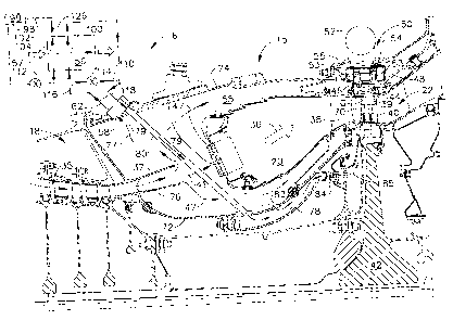
FIG. 2 illustrates in more detail sections of the core
engine 15 including the high pressure compressor 18,
annular combustor 20, and HPT 22 disposed in serial flow
communication. The HPT 22 includes a first stage or HP
turbine nozzle having a row of stator vanes 38 suitably
- 8 -
CA 02716237 2010-09-30
225229
mounted in outer and inner bands. Following the vanes is
a single row of HP turbine blades 40 removably mounted to
the perimeter or rim of a first stage or HP rotor disk
42. The disk 42 is fixedly joined to the first drive
shaft 30 which in turn is fixedly joined to the rotor
disks supporting the compressor blades of the high
pressure compressor 18.
The configuration and operation of the HP compressor 18
and the HPT 22 are conventional for pressurizing the air
34 and expanding the subsequent combustion gases 36 for
extracting energy therefrom. In particular, the pressure
and temperature of the first portion 35 of the fan air 33
increases axially in turn as the air flows downstream
through all of the stages of the compressor blades. The
last row of compressor blades defines the last stage of
the high pressure compressor 18 in this exemplary
configuration and discharges the pressurized air at a
maximum pressure and a correspondingly high temperature
associated with the compressor discharge air 37 (CDP
air).
Radially outer tips 39 of the turbine blades 40 are
radially disposed inside a surrounding turbine shroud 44.
The shroud 44 is typically formed in circumferential
turbine shroud segments 45 suspended from a supporting
annular hanger 46 also formed in segments. The hanger 46
is mounted to a portion of a surrounding annular turbine
casing 48 which has a pair of radial ribs or rails 53
spaced between forward and aft mounting flanges. The
stationary row of turbine shroud segments 45 surrounds
the radially outer tips 39 of the row of rotary turbine
blades 40 and is spaced therefrom to define a relatively
small radial clearance or gap G having an initial or
nominal size.
Leakage of the combustion gases 36 through the gap G
during operation correspondingly reduces efficiency of
- 9 -
CA 02716237 2010-09-30
225229
the turbine and the engine. Differential thermal
expansion and contraction of the turbine blades 40
mounted on their supporting rotor disk and the suspended
turbine shrouds 44 change that nominal radial clearance
during the various modes of operation of the engine from
takeoff to cruise at elevation and to landing on the
runway.
Further illustrated in FIG. 2 are parts of an active
clearance control (ACC) system 50 selectively used to
cool or heat the turbine casing 48 that supports the row
of turbine shrouds 44. The turbine casing 48 itself
therefore defines an ACC mount that supports the hanger
46 and shrouds 44 in turn to control the size of the
radial tip clearance or gap G. An annular supply
manifold 52 surrounds the turbine casing 48 and an
annular impingement baffle 54 is suitably mounted inside
a plenum 55. A impingement baffle 54 has serpentine
portions which closely match the outer profile of two
radial rails 53 of the casing 48. Relatively cool or hot
air is channeled through the impingement baffle 54 to
provide discrete jets of impingement air over the outer
surface of the two rails which in turn affects the radial
expansion and contraction thereof and the corresponding
size of the radial tip gap G during operation.
The core engine 15 further illustrated in FIG. 2 includes
radially inner and outer combustor casings 72, 74 which
radially inwardly and outwardly respectively surround the
combustor 20 and are joined together at the forward ends
to a conventional annular diffuser 76. The diffuser 76
is located at an outlet end of the compressor 18 and
diffuses the first portion 35 of the fan air 33
discharging it as the compressor discharge air 37. A
first portion 47 of the compressor discharge air 37 flows
into a plenum 55 surrounding the annular combustor 20 and
between the inner and outer combustor casings. A second
portion 41 of the compressor discharge air 37 flows into
- 10 -
CA 02716237 2010-09-30
225229
the annular combustor 20. The first cooling circuit 62
includes an annular mixing chamber 78 suitably mounted
below the inner combustor casing 72.
A plurality of circumferentially spaced apart transfer
tubes 80 extend radially through the inner and outer
combustor casings 72, 74 and in to the mixing chamber 78
and used to return a cooled third portion 77 of the
compressor discharge air 37 referred to hereafter as
compressor discharge bleed air 79. The compressor
discharge bleed air 79 is taken from the last stage of
the high pressure compressor 18 through a circuit inlet
58 of the first cooling circuit 62 through the turbine
casing 48 and into the first cooling circuit 62 and
channeled to a heat exchanger 56. The compressor
discharge bleed air 79 is channeled to the heat exchanger
56 from the circuit inlet 58 through a feed tube 60 as
illustrated in FIG. 5. After the compressor discharge
bleed air 79 is cooled in the heat exchanger 56 it piped
back to the plurality of circumferentially spaced apart
transfer tubes 80 through a return tube 64 which
manifolds the cooled compressor discharge bleed air 79 to
the transfer tubes 80.
As illustrated in FIG. 2, the transfer tubes 80 flows the
cooled compressor discharge bleed air 79 into the annular
mixing chamber 78 suitably mounted below the inner casing
72. The inner casing 72 may also include a row of mixing
holes 82 suitably located along the mixing chamber 78 to
provide directly thereto some of the first portion 35 of
the compressor discharge air 37 to mix with the cooled
compressor discharge bleed air 79 in the mixing chamber
78 to prevent over-cooling of the turbine blades 40. The
cooled compressor discharge bleed air 79 or the mixture
of the first portion 35 of the compressor discharge air
37 and the cooled compressor discharge bleed air 79 in
the annular mixing chamber 78 is referred to hereafter as
- 11 -
CA 02716237 2010-09-30
225229
turbine blade cooling air 85 and is used to cool the HP
turbine blades 40.
The first cooling circuit 62 further includes an annular
flow inducer 84 disposed in fluid flow communication
between the outlet end of the chamber 78 and the row of
first stage turbine blades 40 extending radially
outwardly from their supporting rotor disk. The flow
inducer 84 is a stationary component typically including
a row of vanes which tangentially accelerates, meters,
and/or pressurizes the turbine blade cooling air 85 and
injects the turbine blade cooling air 85 into the
rotating first stage rotor disk 42. This is a
conventional component for efficiently channeling and
metering the pressurized turbine blade cooling air 85 to
the axial dovetail slots of the disk 42 for flow into the
inlets found in the dovetails of the turbine blades 40.
The pressurized turbine blade cooling air 85 flows
radially outwardly through the blades 40 and cooling
channels 70 therein and is discharged through the several
rows of outlet holes in the pressure and suction sides of
the blade airfoil in a conventional manner.
The gas turbine engine cooling system 6 and in particular
the first bypass circuit 110 in the first cooling circuit
62 and its first bypass valve 114 allows modulation of
the temperature of the pressurized cooling air 85
directed to the annular flow inducer 84 for cooling the
turbine blades 40. This reduces or eliminates valves and
metering orifices required with conventional turbine
blade cooling flow modulation schemes. The gas turbine
engine cooling system 6 described and illustrated herein
takes advantage of the physical properties of air to flow
more air at low temperatures and less air at high
temperatures through a given orifice size thus modulating
the cooling flow rate by controlling its temperature.
- 12 -
CA 02716237 2010-09-30
225229
This system uses the heat exchanger 56 to provide
cooled-cooling air so that the turbine blade airfoil
materials get maximum cooling flow and lowest temperature
cooling source at high power settings. At low-power
settings, higher temperature cooling flow or elimination
of cooled-cooling may reduce physical cooling flow by as
much as 30% without a mechanical modulated orifice,
particularly in the hot section of the engine.
Significantly increased airframe thermal management
capability may be provided when the engine turbine blades
or hot section no longer requires the highest cooling
levels and the heat exchanger 56, a heat sink, can
provide cooling to various aircraft airframe and engine
systems. Because the engine is at lower power settings
(such as in cruise, decent, or ground operation) during a
significant portion of the flight, the airframe can make
use of this heat sink. Enabling the airframe or
electrical power system to use this heat sink during
these flight phases without additional weight penalty is
valuable to the overall aircraft system.
Illustrated in FIG. 6 is one embodiment of the heat
exchanger 56 in which the first heat exchanger circuit
100 includes a plurality of tube sets 130 having heat
transfer tubes 132 between respective header sets 134 of
inlet headers 138 and outlet headers 140. The compressor
discharge bleed air 79 is channeled to the inlet headers
138 from the feed tube 60, then flowed and cooled through
the heat transfer tubes 132 to the respective outlet
headers 140, and then channeled to the return tube 64
which manifolds the cooled compressor discharge bleed air
79 to the plurality of circumferentially spaced apart
transfer tubes 80. Adjacent tube sets 130 may use common
ones of the inlet and outlet headers 138, 140. The first
heat exchanger circuit 100 is illustrated in FIG. 6 as
having a complete ring of six of the tube sets 130.
- 13 -
CA 02716237 2010-09-30
225229
The compressor discharge bleed air 79 is channeled to the
inlet headers 138 from the feed tube 60 through first
feed connectors 200. The cooled compressor discharge
bleed air 79 is channeled to the return tube 64 through
first return connectors 202 and the return tube 64
manifolds the cooled compressor discharge bleed air 79 to
the plurality of circumferentially spaced apart transfer
tubes 80.
Alternatively, other numbers of the tube sets 130 may be
used and may not be a full ring. The second cooling
circuit 102 may have a similar arrangement of tube sets
and respective header sets 134 of inlet headers 138 and
outlet headers 140 axially or radially adjacent those of
the first heat exchanger circuit 100 and may be disposed
upstream or downstream or radially offset the first heat
exchanger circuit 100.
Illustrated in FIG. 7 is another embodiment of the heat
exchanger 56 in which the first and second heat exchanger
circuits 100, 104 are arranged to alternatively share the
same plurality of tube sets 130 and the heat transfer
tubes 132 between the respective header sets 134 of the
inlet headers 138 and the outlet headers 140. The
compressor discharge bleed air 79 is channeled to the
inlet headers 138 from the feed tube 60 through first
feed connectors 200. Next, the compressor discharge
bleed air 79 is flowed and cooled through the heat
transfer tubes 132 to the respective outlet headers 140.
Then, the cooled compressor discharge bleed air 79
channeled to the return tube 64 through first return
connectors 202 and the return tube 64 manifolds the
cooled compressor discharge bleed air 79 to the plurality
of circumferentially spaced apart transfer tubes 80.
Adjacent tube sets 130 may use common ones of the inlet
and outlet headers 138, 140.
- 14 -
CA 02716237 2010-09-30
225229
A feed pipe 150 channels hot heat source airflow 154 from
the heat source 98 (illustrated in FIG. 2) through second
feed connectors 206 to the inlet headers 138 and then
flows and cools the heat source airflow 154 through the
heat transfer tubes 132 to the respective outlet headers
140. Next, the cooled heat source airflow 154 is
channeled through second return connectors 208 to a return
pipe 156 for return to the heat source 98. The first and
second bypass valves 114, 122 must be operated so that
only compressor discharge bleed air 79 or heat source
airflow 154 is allowed to flow to the heat exchanger 56 at
any given time. One way valves such as flapper valves may
be operably disposed in the first and second cooling
circuits 62, 102 to prevent backflow into the heat
exchanger through the feed tube 60 or the feed pipe 150.
The gas turbine engine temperature modulated cooling
system 6 is operated to modulate the flowrate of the
first airflow 118 by modulating the amount or the portion
116 of the first airflow 118 in the first cooling circuit
62 to flow through the first heat exchanger circuit 100
in the heat exchanger 56. The greater the amount or the
portion 116 of the first airflow 118 allowed to flow
through the first heat exchanger circuit 100 the greater
the flowrate of the first airflow 118 delivered to a hot
component or components to be cooled such as the HP
turbine blades 40. One method of operating the cooling
system 6 includes opening the first bypass valve 114 and
bypassing the first airflow 118 in the first cooling
circuit 62 around the first heat exchanger circuit 100
and the heat exchanger 56 during low power operation such
as during cruise, decent, or ground operation. The
method also includes closing the first bypass valve 114
and flowing the first airflow 118 in the first cooling
circuit 62 through the first heat exchanger circuit 100
in the heat exchanger 56 during high power operation such
as during takeoff or climb. This method also allows the
- 15 -
CA 02716237 2010-09-30
225229
airframe to make use of the heat sink capability of the
heat exchanger 56 during a significant portion of the
flight by operating the control valve 112 to either
modulate or open and close the control valve 112 valve in
the second cooling circuit 102 to cool the heat producing
source or heat source 98 such as may be found in an
aircraft airframe 96 or which may be an electrical power
system 99 in the aircraft or aircraft gas turbine engine.
The gas turbine engine temperature modulated cooling
system 6 uses the physical properties of air to flow more
air at low temperatures and less air at high temperatures
through a given orifice size. Using cooled-cooling air
the turbine materials get maximum cooling flow and lowest
temperature cooling source at high power settings. At
low-power settings, higher temperature cooling flow or
elimination of cooled-cooling will reduce physical
cooling flow by as much as 30% without a mechanical
modulated orifice. The gas turbine engine temperature
modulated cooling system 6 can provide significantly
increased airframe thermal management capability when the
engine hot section no longer requires the highest cooling
levels. Because the engine is at lower power settings
(in cruise or decent) during a significant portion of the
flight, the airframe can make use of this heat sink.
Enabling the airframe or electrical power system to use
this heat sink during these flight phases without
additional weight penalty is valuable to the overall
aircraft system.
While there have been described herein what are
considered to be preferred and exemplary embodiments of
the present invention, other modifications of the
invention shall be apparent to those skilled in the art
from the teachings herein and, it is therefore, desired
to be secured in the appended claims all such
modifications as fall within the true spirit and scope of
the invention.
- 16 -