Note: Descriptions are shown in the official language in which they were submitted.
CA 02716605 2010-08-23
WO 2009/106219 PCT/EP2009/00872
1
Separating Device
The invention relates to a separating device for separating individual
container products
from a frame assemblage which consists of a plastic material, particularly
polypropylene, with at
least one punching device which at least partially separates the container
product from the frame
waste.
The prior art (DE 199 26 329 Al) discloses methods and devices for producing
container
products from plastic, how they are supplied to a generic separating device
which is then used to
separate these individual container products from a frame assemblage using a
cutting or punching
device.
To produce the respective container product, first a tube of plasticized
plastic material is
extruded into a molding device. One end of the tube is closed by heat sealing
and by producing a
pneumatic pressure which acts on the tube, the latter is expanded, and to form
the container it is
placed against the forming wall of the molding device consisting of two
opposite molding tools.
Then the plastic container is filled under sterile conditions within the
molding device by way of a
corresponding filling mandrel, and after removing the filling mandrel, it is
then hermetically sealed
with the formation of a definable head geometry. For the purpose of forming
the actual plastic
container, in which fluid is later stored, two container forming jaws are
being moved by hydraulic
driving means toward one another to obtain the closed position and are being
moved in opposite
directions away from one another into one of their open positions. In order to
achieve very high
CA 02716605 2010-08-23
WO 2009/106219 PCT/EP2009/00872
2
ejection rates of container products here, DE 103 23 335 Al describes a multi-
station arrangement,
where the various molding steps are divided among different stations located
in succession on an
imaginary circular arc so as to form a type of carousel arrangement which
enables very high cycle
frequencies for the plastic material to be ejected in the form of container
products.
Since the contents to be placed in the respective container product is often
very susceptible
to ambient media, especially if it is, for example, a highly sensitive
pharmaceutical, the prior art
focuses on, for example, covering the fill opening of the container tube by a
sterile barrier under a
sterile space at least from its formation to filling of the pertinent
container, and very good results can
be achieved here when, as shown in DE 10 2004 004 755 Al, by means of the
indicated barrier a
sterile medium is moved in the direction of the container fill opening using a
media conveyance
device in order to further improve the sterility. Another or an additional
measure to increase sterility
is to simply provide higher processing temperatures, for example, when
producing the tube for the
container product or during the filling process of the fill material, where an
increased processing
temperature finds its limits when the plastic material which is frequently
used, such as polyethylene,
is temperature-sensitive, but can otherwise be easily processed in the
pertinent production devices
and is preferred.
Otherwise, in addition to atmospheric oxygen, other gases can also diffuse
later into the
interior of the container through the thin polyethylene wall during storage
and in distribution of the
container product which has been produced under sterile conditions and in this
way can damage the
sensitive container contents or even make them unusable.
In order to eliminate this latter disadvantage, in the prior art production
methods for these
container products have been suggested (DE 103 47 907 Al and DE 103 47 908 Al)
which relate to
so-called co-extrusion production methods in which the container is built up
from several layers of
plastic material, often at least one of the layers being used as a barrier
layer. Here five and more
CA 02716605 2013-10-02
3
layers, for example, formed from polyethylene and low-density polyethylene as
well as copolymers
(ethylene-vinyl alcohol copolymers) can form the multi-layer container wall
which in this case then
forms an effective barrier layer; but these methods are cost-intensive in
practical implementation.
This makes the respective container product correspondingly more expensive.
If the individual container products arrive filled from the respective
production machine,
they emerge as ampule blocks in which several ampules or containers located
next to one another in
the manner of a block assemblage or frame assemblage have a common wall with
one another. In
order to detach the containers or ampules from the block or frame assemblage,
they are cut out or
punched out along edge zones, in this respect then a certain amount of frame
waste being produced
which can be recycled with modem techniques. DE-PS 38 31 957 discloses a
method for producing
hollow container products from plastics which initially emerge as an ampule
block or a frame
assemblage, in the edge zone of the frame waste a hollow body being
additionally molded in; this
increases the stability of the frame assemblage and also helps facilitate
separation of the container
product from the frame waste by means of the separating device used in each
case.
Proceeding from this prior art, an object of the invention is to devise a
separating device
with which the container products, regardless of the plastic material
comprising them, can be
separated from the frame assemblage at high speed, and which in addition to a
high degree of
operating reliability also has relative low production costs. This object is
achieved by a separating
device with the features described herein.
According to an aspect of the present invention, there is provided a
separating device
for separating individual container products from a frame assemblage which
consists of a
plastic material, particularly polypropylene, with at least one punching
device which at least
partially separates the container product from the frame waste, characterized
in that the
punching device can be moved from an initial position into the punching
position along a
punching axis and vice versa by means of a ball screw which can be driven by a
drive unit,
especially in the form of an electric motor.
According to another aspect of the invention, there is provided a separating
device
for separating individual container products from a frame assemblage which is
made from a
plastic material, comprising at least one punching device which at least
partially separates the
respective container product from a frame waste, the at least one punching
device
CA 02716605 2013-10-02
3a
being moveable by means of a drive that can be driven by a drive unit along a
punching axis
from an initial position into a punching position and vice versa,
wherein the drive is a ball screw which, by means of a damping system,
prevents
overloading of the ball screw during a punching process, and wherein the
damping system has
at least one energy store that decouples the punching device from the ball
screw.
In that, as specified herein, the punching device can be moved from an initial
position
into the punching position along a punching axis and vice versa by means of a
ball screw
which can be driven by a drive unit, especially in the form of an electric
motor, separation can
be done with a very high speed, dictated by the threaded spindle which can be
driven by
means of the electric motor, and additional mechanical components for applying
a positive force
CA 02716605 2010-08-23
WO 2009/106219 PCT/EP2009/00872
4
to the punching body in setting up the separation line can be omitted. The
ball screw used makes it
possible to reduce the energy used correspondingly; this benefits economical
operation of the
separating device.
In particular, it has been shown that with the separating device according to
the invention,
polypropylene as the wall material can be used for the container products, a
plastic material which is
brittle compared to a polyethylene material and which otherwise can be
processed only with
difficulty using conventional punching and cutting means for container
separation. To the extent
conventional separating devices are used, it has been shown that with respect
to the very high
processing temperatures of polypropylene it would be necessary to wait several
minutes until the
punching and cutting process is possible at all. But this would necessarily
lead to very long retention
sections and/or additional cooling means being necessary for the container
products to be separated
in order to be able to undertake separation at all without scrap. Due to the
punching device which
can be triggered by way of the ball screw, clean separation can take place
without these waiting
times or additional cooling means, simply by the respective container product
being knocked out of
the still warm or hot frame assemblage at high speed by means of the spindle
drive along the
intended punching lines. It is surprising to one with average skill in the art
in the field of these
separating devices that he will arrive at these clean separating punching
lines with the cutting edges
of the punching device which are kept relatively blunt and which need not be
further reworked
(ground) or otherwise maintained; this was not possible in the past with
devices in the prior art.
The advantage of using polypropylene material instead of polyethylene or a
coextruded
multilayer composite consisting of LDPE/MDPE is that the polypropylene
material at higher
temperatures (121 C) can be autoclaved, the polypropylene material being
obtainable from only
one extrusion head in a much more favorable manner than the described
multilayer system. Thus,
ultimately each individual layer to be produced in a multilayer system
requires its own extrusion
CA 02716605 2013-10-02
head in the production machine; this increases production cost accordingly
also from the control
side.
Provided that the separating device according to the invention is used with
the punching
device which can be driven by the ball screw, this application is not limited
thereto; rather, there are
a host of possible applications, and the separating device according to the
invention can also be used
for other plastic materials such as polypropylene or multilayer plastic
systems for separation of the
container product as necessary.
In one preferred embodiment of the separating device according to the
invention, a damping
system prevents overloading of the ball screw in the punching process. The
damping system has
preferably at least one energy storage (compression spring) which decouples
the punching device
from the ball screw at least during the punching process. In this way the
punching process can be
initiated especially carefully and the ball screw is relieved; this increases
its service life.
The separating device according to the invention is made in the form of a
column structure
with individual guide and adjustment plates which are spaced apart from one
another, the column
structure in addition to so-called adjustment columns also having guide
columns which together
with the assignable plates lead to a highly reinforced pedestal construction.
=
Other advantageous embodiments of the separating device according to the
invention
are described herein.
According to another aspect of the present invention, there can be provided
the
separating device described herein, characterized in that a damping system
prevents
overloading of the ball screw in the punching process.
According to another aspect of the present invention, there can be provided
the
separating device described herein, characterized in that the damping system
has at least one
energy storage, preferably in the form of a compression spring which decouples
the punching
device from the ball screw.
CA 02716605 2013-10-02
5a
According to another aspect of the present invention, there can be provided
the
separating device described herein, characterized in that the energy storage
of the damping
system extends between a stop plate which is connected to the ball roller
spindle of the ball
screw, and a guide plate with the punching device.
According to another aspect of the present invention, there can be provided
the
separating device described herein, characterized in that the stop plate in
the raised position
of the punching device strikes a stop of the guide plate and that the guide
plate is guided
along at least one guide column.
According to another aspect of the present invention, there can be provided
the
separating device described herein, characterized in that to adjust the
punching plane of the
punching device an adjustment means is used which has an adjustment plate
which can be
vertically adjusted by means of at least one adjustable column.
According to another aspect of the present invention, there can be provided
the
separating device described herein, characterized in that the respective guide
column of the
guide plate extends through the adjustment plate and is at least partially
fixed on it, and that
the respective adjustable column is farther away from the punching axis than
the respective
guide column.
According to another aspect of the present invention, there can be provided
the
separating device described herein, characterized in that the punching device
is at least
partially encompassed by a hold-down device which can be raised and lowered by
means of
at least one working cylinder which is connected to the adjustment plate.
According to another aspect of the present invention, there can be provided
the
separating device described herein, characterized in that the hold-down device
presses the
frame assemblage with the container products for a punching process against a
die which has
recesses for at least partially accommodating the container products.
According to another aspect of the present invention, there can be provided
the
separating device described herein, characterized in that in the adjustment
plate there is an
CA 02716605 2013-10-02
5b
ejector means which ejects container products of the assemblage which may have
remained
in the punching device.
The separating device according to the invention is detailed below using one
exemplary embodiment as shown in the drawings. Here the figures are schematic
and not to
scale.
CA 02716605 2013-10-02
6
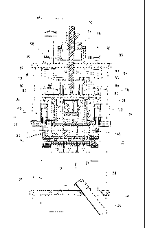
FIG. 1 shows a frame assemblage which is depicted in a face top view,
consisting of the
ampule block itself and the frame waste;
FIG. 2 shows an ampule block from which the frame waste has been largely
removed, and
in which the individual container products are detachably connected to one
another
with intermediate wall webs as a commercial unit;
FIG. 3 seen partially in a view, partially in a longitudinal section,
shows a front view of the
separating device as a whole;
FIGS. 4 and 5 show a front view of the separating device corresponding to FIG.
3, shown without a
punching device and die and a top view of the separating device as shown in
FIGS. 3
and 4;
FIGS. 6 and 7 show a side view seen in the direction of looking at the
separating device along
arrow X in FIG. 4 and a section along line A-A in FIG. 6;
FIG. 8 shows a top view of the punching die as shown in FIG. 3 with a
transport means for
delivery of the container products which are to be separated from the frame
assemblage.
In some of the figures, components of the overall device are omitted for
purposes of clarity
of the solution according to the invention.
The frame assemblage which is shown in FIG. 1 and designated as a whole as 10
consists of
a plastic material, in this case of a polypropylene material. The frame
assemblage 10 is composed
of the actual container products 12 and the so-called frame waste 14 which can
be
CA 02716605 2010-08-23
WO 2009/106219 PCT/EP2009/00872
7
separated from the actual container products 12. When the container products
12 are separated from
the frame waste 14, an ampule block from which the frame waste 14 has been
removed as shown in
FIG. 2 results, the individual containers or individual ampules 12 being
detachably connected to one
another by way of the remaining intermediate wall webs 16 of the frame waste
14, the intermediate
wall webs 16 making it possible for the respective container product 12 to be
separated from the
other containers 12 remaining in the block in a type of a twist-off motion.
The respective container product 12 is known in the prior art, and the above-
described
ampule block solution is shown, for example, in DE 38 31 957 Cl. The basic
form shown in FIGS.
1 and 2 constitutes only one type of one exemplary embodiment, and the
container geometries in
particular can be stipulated by the user within a widely drawn scope. To
release the respective
container contents, generally in the form of a fluid which has been added
beforehand, a twist-off cap
18 is used which likewise can be separated via a corresponding scored site by
a twist-off motion
from the remaining container product 12 by way of a handle 20, with the result
that the fluid can be
removed via the cleared container opening. Other container opening solutions
such as dropper caps,
etc., can likewise be implemented.
On the bottom of the frame assemblage 10 as shown in FIG. 1 a type of blind
holes 22 are
made, and using the pins of a transport means (not shown) which engage the
blind holes 22 on the
lower edge of the frame waste 14, the frame assemblage 10, consisting of the
container products 12
and the frame waste 14, is removed from the tool of a production machine which
is not detailed, due
to the higher stability of the frame waste in the form of an inherently closed
waste edge zone,
removal being easily and reliably possible when the plastic of the frame
assemblage 10 has not yet
completely cooled. This configuration is conventional and is shown, for
example, in EP 0 359 971
A2 so that it will not be further detailed here.
CA 02716605 2010-08-23
WO 2009/106219 PCT/EP2009/00872
8
Furthermore, it is also possible to arrange the blind holes 22 or other
engagement option for
a transport unit, viewed in the direction of looking at FIG. 1, laterally in a
vertical alignment as part
of the frame waste 14 on the latter, provided that, instead of the
horizontally running transport
direction which is shown in FIG. 1, a direction perpendicular thereto, i.e.,
in the direction of the
longitudinal axes of the container, is desired. How the frame assemblage is
suitably placed in the
separating device as a cutting or punching device or is retrieved from it
again is, for example, the
subject matter of DE 38 32 566 C2 in which a moving transport hook engages the
transport recesses
in the frame waste of the frame assemblage 10.
For a separating or punching process, viewed in the direction of looking at
FIG. 8,
originating from a production machine which is not detailed, the respective
frame assemblage 10
moves from right to left into a die 24, the die 24 shown in FIG. 8
constituting a receiving option for
three frame assemblage arrangements 10 next to one another, with five
connected container
products 12 each. The respective container products 12 originating from the
production machine are
connected to one another by way of the frame waste 14, after the punching or
separating process a
container assemblage as shown in FIG. 2, viewed in the direction of looking at
FIG. 8, having to
leave the die 24 on the left side in order to be then packed into the
corresponding packaging units
for further transport. Moving the respective frame assemblage 10 with the
container products 12
into and out of the die 24 by way of the transport means 26 is prior art so
that it will not be further
detailed here.
FIG. 3, viewed in the direction of looking at arrow Y of FIG. 8, shows a rear
view of the die
24 again with three frame assemblage units 10 with five container products 12
each. As furthermore
follows from the backward front view as shown in FIG. 3, the die 24 consisting
of a solid metal
block is moved upright via support columns 28 which extend between a die frame
30 for the die 24
and a lower base plate 32 which a slide 34 reaches through which is used to
remove the plastic
waste from the separating device. The lengths of the four support columns 28
are preferably
CA 02716605 2010-08-23
WO 2009/106219 PCT/EP2009/00872
9
adjustable in order to enable alignment of the die 24 according to given
production criteria. The
rectangularly made lower base plate 32 allows a modular structure for the
entire separating device
so that a unit results which is easy to install and which can be easily
integrated into the sequence of
production machines which are already present.
The separating device shown in FIG. 3 has a punching device which is
designated as a
whole as 36 and which comparably to the die 24 consists of a solid metal frame
block and can be
made in several parts. To increase the punching or cutting pressure, a block-
like charge weight 38
can be used, whose bottom is joined to individual upper dies 40 which in turn
on their bottom have
punching blades 42 which enable separation of the frame waste 14 from the
container products 12 in
order to move from a preliminary product as shown in FIG. 1 to the finished
container product
assemblage as shown in FIG. 2. In this respect the strip-like punching blades
42 travel into the
intermediate intervals between the container products 12 held in the die 14
for each frame
assemblage 10. This arrangement is only exemplary to the extent one or two
units of the frame
assemblage 10 or larger units of frame assemblage arrangements with a
different number of
container products 12 can also be processed. The respective arrangement is
dictated by the machine
operator and his requirements.
To move the block-like punching device 36 along a punching axis 44, a ball
screw
designated as a whole as 46 is used which can be actuated by an electric motor
48. The electric
motor 48 can be especially a conventional servo motor with short operating
times relative to the
respective switchover direction. The ball screw 46 has a rod-like ball roller
spindle 50 which,
guided in a threaded bushing 52 viewed in the direction of looking at FIG. 3,
can be moved down
from the raised position shown in FIG. 3 into the punching or separating
position along the
punching axis 44. For this purpose, the electric motor 48 drives the threaded
bushing 52 by means
of an output pinion which is not shown, for example, by means of a toothed
frame drive which is
not detailed; the bushing is guided to be able to rotate in a rotary receiver
54. This belt drive runs
CA 02716605 2010-08-23
=
WO 2009/106219
PCT/EP2009/00872
within an upper base plate 56 which terminates the separating device as a unit
toward the top. The
electric motor 48, the rotary receiver 54 with the threaded bushing 52, and
part of the ball roller
spindle 50 project with a defmable excess length over the upper base plate 56,
viewed in the
direction of looking at FIG. 3.
To reinforce the overall system, four adjustable columns 58 extend between the
lower base
plate 32 and the upper base plate 56 and, relative to the punching axis 44,
are arranged in pairs
diametrically opposite one another (cf. FIG. 7). The four adjustable columns
58 as part of an
adjustment means designated as a whole as 60 extend through a square
adjustment plate 62 which is
provided with four adjustable bushings 64 which extend around the respective
adjustable column
58. Another part of the adjustment means 60 on the top of the upper base plate
56 comprises two
working cylinders 66 (cf. FIG. 6) which, made in the manner of hydraulic or
pneumatic cylinders,
by means of adjustable rods 68 which are fixed with their lower end on the
adjustment plate 62,
induce its vertical adjustment along the adjustable columns 58. For the sake
of visual simplicity,
FIG. 3 does not show this cylinder arrangement 66 with adjustable rods 68. For
the sake of
simplicity FIGS. 4 and 6 have also omitted the punching device 36. With the
indicated adjustment
means 60, depending on the conditions of use on site, the punching plane for
the punching device
36 can be adjusted, and viewed in the direction of looking at FIG. 4 the
adjustment plane toward the
bottom can be bordered by a stop body 70.
Furthermore, there is a damping system which is designated as a whole as 72,
which is
shown in FIG. 3, and which also contributes to helping prevent overloading of
the ball screw 46 in
operation, especially in a punching process itself. For this purpose the
damping system 72 has an
energy storage in the form of two compression springs 74 which the punching
device 36 decouples
from the ball screw 46. For this purpose, the two compression springs 74 with
their top which is
shown in the direction of looking at FIG. 3 are supported on a stop plate 76
which is permanently
connected to the lower end of the ball roller spindle 50 by way of a fixing
nut 78. The lower end of
CA 02716605 2010-08-23
=
WO 2009/106219
PCT/EP2009/00872
11
the respective compression spring 74 is supported on a guide plate 80, whose
bottom, permanently
connected by way of retaining rods 82, is adjoined by the punching device 36.
Instead of the
indicated compression springs 74 as the energy storage, another solution can
be used, for example,
in the form of a disk spring or the like.
In the embodiment as shown in FIG. 3, however, the respective compression
spring 74
encompasses a guide pin 84 which forms a guide for the stop plate 76 which in
this respect can be
moved back and forth between two end positions by means of the ball roller
spindle 50. The lower
possible end position is formed by way of lower buffer bushings 86 which can
be made as an
elastomer material and encompass the respective compression spring 74 in
addition to the guide pin
84. In the other stop situation which is pointed upward, the top of the stop
plate 76 has annular
vibration compensators 88 which are supported on angled boundary strips 90,
provided that the ball
roller spindle 50 assumes its nonactuating position assumed in FIG. 3.
When the electric motor 48 is started and a punching process is to be
undertaken, the ball
roller spindle 50 is moved down along the punching axis 44, viewed in the
direction of looking at
FIG. 3, and the stop plate 76 is entrained against the action of the two
compression springs 74 until
it comes into contact with the top of the buffer bushings 86, and in the
continuing downward motion
then the punching process is induced by the punching device 36 for the
respective frame assemblage
10. If the ball roller spindle 50 is moved up in the reverse sequence, the
stop plate 76 is entrained
upward until it engages, from underneath, the angular offsets of the two
boundary strips 90 as
shown in FIG. 3, this striking motion being cushioned by the vibration
compensators 88.
The guide plate 80 is in turn guided along four guide columns 94 by way of the
corresponding guide bushings 92. As FIG. 7 shows in particular, these guide
column 94 are in turn
located diametrically opposite one another to the punching axis 44 and lie
within the outer
peripheral plane with the four adjustable columns 58. In order to be able to
ensure that the
CA 02716605 2010-08-23
WO 2009/106219 PCT/EP2009/00872
12
individual components can move smoothly, the block-like punching device 36 as
a whole extends
through the corresponding rectangular recess in the adjustment plate 62. The
four guide columns 94
are guided on the top of the upper base plate 56 in receivers 96 which are
otherwise held on their
lower opposite end (cf. FIG. 4) in guide receivers 98 on the bottom of the
adjustment plate 62,
which guide receivers allow movement for the guide columns 94 in the axial
direction parallel to the
punching axis 44, but transversely thereto they enable a defined position in
the radial direction. In
this way relative adjustment of the adjustment plate 62 to the guide plate 80
is possible.
The punching device 36 is furthermore at least partially encompassed by a hold-
down
device which is designated as a whole as 100 and which, made as a plate-like
hold-down frame, can
be raised and lowered by two working cylinders 102 (see FIG. 3). In the
lowered position the hold-
down device 100 is used to press down the frame waste 14 in the direction of
the die frame 30 in
order in this way to ensure clean contact of the respective frame assemblage
10 in the pertinent
recess of the die 24. The required working cylinders 102 are preferably driven
hydraulically,
pneumatically, or servoelectrically, and are permanently connected with their
housing parts to the
adjustment plate 62 so that the hold-down device 100 can move relative to the
adjustment plate 62.
In order, however, to be able to ensure undisrupted operation for the stop
plate 76 in the sense that it
can move up and down parallel to the punching axis 44, as follows especially
from FIG. 7, the stop
plate 76 is provided with two U-shaped recesses through which the housing
parts of the respective
working cylinder 102 extend.
Furthermore, the separating device according to the invention has an ejector
means (FIG. 7)
which is designated as a whole as 104 and which ejects the plastic waste of
the assemblage 10
which may remain, for example, in the punching device 36 via the slide 34. For
this purpose the
ejector means 104 preferably has two hydraulically, pneumatically, or
servoelectrically actuatable
working cylinders 106 which actuate two ejector pins 108 which, viewed in the
direction of looking
CA 02716605 2010-08-23
WO 2009/106219 PCT/EP2009/00872
13
at FIG. 6, project underneath the adjustment plate 62; conversely, the working
cylinders 106 are
located above the adjustment plate 62.
For the sake of better understanding, a sequence for a punching process will
be described
below. The strip of ampules with the three frame assemblage units 10 is
transported into the
separating device in the manner of a punch by way of a definable cycle
advance. When the
respective frame assemblage 10 has advanced to above the die 24, the block-
like punching device
36 is moved into the punching position by vertical lowering within the scope
of the cycle advance.
Afterwards, the hold-down device 100, actuated pneumatically, presses from
overhead on the strip
of ampules and clamps it between the hold-down device 100 and the die 24.
Afterwards, the actual
punching stroke is triggered, the electric motor 48 actuating the ball screw
46 in the connected
position. The described damping system 72 prevents overly large impacts from
being transmitted to
the threaded spindle during the punching process, for example, in the form of
the ball roller spindle
50. When the punching stroke has ended, pneumatically actuated ejector pins
108 press the ampules
12 which may have become caught in the punch of the punching device 36 onto a
support (slide 34).
One cycle behind the punching position of the ampules 12, shortly after
punching of the ampules,
the waste strip in the form of the frame waste 14 is crushed by pneumatic
punching (not shown).
After the punching processes, ejector pins 108, the punch in the form of a
punching device
36 with the punching blades, and the hold-down device 100 and support for the
cycle advance move
up again and the next cycle can begin. For better accessibility in
instnllation and maintenance a so-
called maintenance stroke can be executed in which the upper structure and
therefore the adjustment
plate 62 are moved away toward the top. The ball screw 46 with the triggerable
threaded spindle
allows very prompt feed processes and delivery of very high punching forces
via the punching
device 36; this had not been achieved in this way to date with conventional
means. So that the
punching device 36 does not collide with the lower die 24, there can be stops,
detection sensors,
and/or monitoring electronics for the electric motor 48.