Note: Descriptions are shown in the official language in which they were submitted.
CA 02716749 2012-05-09
- 1 -
A METHOD AND SYSTEM FOR FACILITATING ASSEMBLY OF A
DRILLING RIG
The present invention relates to a method and system
for facilitating assembly of a drilling rig.
The prior art discloses a variety of rigs used in
drilling and various wellbore operations; for example,
and not by way of limitation, U.S. Patents 3,340,938;
3,807,109; 3,922,825; 3,942,593; 4,269,395; 4,290,495;
4,368,602; 4,489,526; 4,569,168; 4,837,992; 6,634,436;
6,523,319; and 7,306,055 and the references cited in
these patents. The
prior art discloses a variety of
systems and methods for assembling and erecting a
drilling rig; for example, and not by way of limitation
nor as an exhaustive listing, the disclosures in U.S.
Patents: 2,993,570; 3,201,091; 3,262,237; 3,749,183;
4,221,088; 4,269,009; 4,292,772; 4,305,237; 4,478,015;
4,587,778; 4,630,425; and 4,932,175.
Often drilling rigs and related systems, structures,
equipment, and apparatuses are delivered to a site,
assembled, raised, disassembled, and transported to a new
site. It is important that drilling rigs and their
components be easily transported, assembled, and erected.
In many prior rigs and erection methods, rig
components and structures used with a rig are raised by a
crane and positioned on a rig's drill floor. Various
problems and disadvantages are associated with using a
crane. A crane is typically a large apparatus which is
transported to a drilling site where it is assembled
and/or made ready for lifting and locating rig
components.
In accordance with the present invention, there is
provided a method for facilitating assembly of a drilling
CA 02716749 2012-05-09
- 2-
rig, the method comprising the steps of assembling a
substructure of a drilling rig, wherein the substructure
comprises a lower structure arranged on the ground and an
upper structure arranged thereabove and connected thereto
characterised in that said upper structure has an upper
open space, the lower structure has a lower open space,
at least a portion of the upper open space above the
lower open space, moving with a vehicle on the ground a
floor section into at least a portion of said upper and
lower space and securing the floor section to the
substructure.
Preferably, the floor section is initially connected
to the vehicle, the method further comprising the steps
of disconnecting the floor section from the vehicle and
moving the vehicle away from the drilling rig.
Advantageously, the method further comprises the
step of installing a drawworks on the substructure.
Preferably, the drawworks is connected to the
substructure before the floor section is moved into the
open space in the upper and lower structures.
Preferably, the floor section comprises a rack for
racking pipes, casing and tubulars to be used in the
drilling of a wellbore.
Advantageously, the method further comprises the
step of assembling a mast and connecting the assembled
mast to the substructure. Preferably, the mast is
connected to the substructure and then raised to a
vertical position and fixed to the substructure before
the floor section is moved into the open space in the
upper and lower structures. Preferably, the method
further comprises the step of erecting the mast on the
substructure.
CA 02716749 2012-05-09
- 3-
Advantageously, the method further comprises the
step of installing a rig structure on the substructure.
Preferably, the rig structure is connected to the
substructure and after the floor section is moved into
the open space in the upper and lower structures and
connected to the substructure. Advantageously, the rig
structure is one of doghouse, cabin, and control room.
Advantageously, the floor section is a central floor
section comprising an opening for a rotary table.
Preferably, the method further comprises the step of
fitting a rotary table into the floor section before the
floor section is moved into the open space in the upper
and lower structures.
Advantageously, the method further comprises the
step of installing rig equipment on the substructure.
Preferably, the rig equipment is at least one of: winch,
iron roughneck, independent rotary table drive, and
rotary table.
Advantageously, the method further comprises the
step of raising with raising apparatus the upper
structure to an operational height. Preferably, the
raising apparatus is arranged to act between the upper
and lower structures.
Preferably, the upper structure comprises box
sections, such as box girders and flooring formed of box
section material, such as steel. Advantageously, the
floor section covers a substantial portion of the upper
open space. Preferably, the floor section is connected to
the upper structure.
The present invention also provides a system for
facilitating assembly of a drilling, the system
comprising assembling a substructure of a drilling rig,
CA 02716749 2012-05-09
- 4-
wherein the substructure comprises a lower structure
arranged on the ground and an upper structure arranged
thereabove and connected thereto characterised in that
said upper structure has an upper open space, the lower
structure has a lower open space, at least a portion of
the upper open space above the lower open space, moving
with a vehicle on the ground a floor section into at
least a portion of said upper and lower space and
securing the floor section to the substructure.
The present invention also provides a method for
facilitating erection of a drilling rig, the drilling rig
comprising at least a part of a rig floor and a base
having at least one collapsible leg therebetween, the
method comprising the steps of attaching the mast to the
at least a part of the rig floor, raising the mast to a
vertical position and subsequently raising the at least
part of the rig floor on the collapsible legs relative to
the base.
Preferably, the mast comprises a first portion and
second portion, the method further comprising the step of
connecting the first and second portions before the mast
is raised to the vertical position.
Advantageously, the second portion is telescopically
extendible, the method further comprising the step of
telescopically extending said second potion once the mast
has been raised. Preferably, the step of telescopically
extending the second portion is carried out once the at
least part of the rig floor has been raised.
Advantageously, the step of attaching the mast to
the at least part of the rig floor is carried out with a
connection which allows rotation of the mast thereabout.
Preferably, to allow the mast to rotate about the
CA 02716749 2012-05-09
- 5-
connection from a substantially horizontal position to a
vertical position.
Advantageously, the method further comprises the
step of attaching a top drive or other motor to rotate a
drill string to a part of the mast before the mast is
raised, the top drive raised with the mast.
Advantageously, the mast may comprise a track on which
the top drive is fitted, or the top drive may be
temporarily fixed to the mast, until the mast is raised,
at which point the top drive is attached to a travelling
block. Preferably, the mast comprises a track on which
the top drive is, in use, raised and lowered.
Advantageously, the mast further comprises a crown block,
the crown block fitted to the mast before the mast is
raised. Preferably, the mast further comprises a
travelling block, the travelling block removably attached
to the mast before the mast is raised.
Preferably, a raising arm is arranged between the
mast and the base, the method comprising the step of
activating the raising arm to raise the mast. Preferably,
the raising arm is a telescopically extendible.
Advantageously, the raising arm is hydraulically
actuated. Advantageously, no cranes, lines, winches or
drawworks are used to raise the mast.
Advantageously, the method further comprises the
step of attaching a racking board to the mast before the
step of raising the mast.
Preferably, the step of raising the at least part of the
rig floor is carried out to an operational height,
advantageously, such that drilling and rig operations can
commence. Preferably, support legs are fixed between the
rig floor and the base to support the rig floor when the
CA 02716749 2012-05-09
- 6-
rig floor is at operational height..
Preferably, the at least part of the rig floor
comprises a structural support, the method further
comprising the step of installing a floor section before
carrying out the step of raising the at least part of the
rig floor.
Advantageously, the structural support comprises box
sections forming rig floor side sections.
The present invention, in certain aspects, provides
a drilling rig with structure manipulation and erection
apparatus and methods for using such apparatus to erect a
rig without using a crane, without winching up cables,
and without lifting items and equipment with a drawworks.
The present invention discloses, in certain aspects,
a method for assembling a drilling rig, the method
including: assembling a substructure of a drilling rig,
the assembly including connecting an upper box to a lower
box, the upper box having an upper open space, the lower
box having a lower open space, and the upper open space
above the lower open space; moving with a vehicle on
ground a floor section connected to and supported by the
vehicle into open space including the upper open space
and the lower open space; and securing the floor section
to the substructure.
The present invention discloses, in certain aspects,
a substructure for a drilling rig, the substructure
including: an upper box with an upper open space; a lower
box with a lower open space; the upper open space above
the lower open space and comprising a substructure space;
the substructure space sized for selective receipt
therein of a vehicle; and a floor section connectible to
and supportable by the vehicle for movement into the
CA 02716749 2012-05-09
- 7-
substructure space, the floor section connected to the
substructure.
For a better understanding of the present invention,
reference will now be made, by way of example, to the
accompanying drawings, in which:
Figure lA is a top view of part of an upper box of a
rig floor of the drilling rig in accordance with the
present invention;
Figure 1B is a top view of the upper box shown in
Figure 1A above a base of the drilling rig in accordance
with the present invention;
Figure 1C is a top view of the base shown in Figure
1B;
Figure 1D is a top view of the upper box and of the
base box shown in Figure 1B, with further structural
members;
Figure 2A is a top view of a part assembled drilling
rig in a step in a method of installing a drawworks in
the assembly of a drilling rig in accordance with the
present invention;
Figure 2B is a top view of the part assembled
drilling rig in a further step in the method of
installing the drawworks, with a mast raising cylinder
shown;
Figure 2C is a side view of the part assembled
drilling rig in the step in the method of installing the
drawworks shown in Figure 2B;
Figure 2D is a top view showing the drawworks
installed on the part assembled drilling rig;
Figure 3A is a top view of the part assembled
drilling rig in a step in the method for installing and
CA 02716749 2012-05-09
- 8-
erecting a mast in the assembly of a drilling rig in
accordance with the present invention;
Figure 3B is a side view of the part assembled
drilling rig in a further step in the method of
installing and erecting the mast;
Figure 3C is a side view of the part assembled
drilling rig, with a vehicle carrying the mast in a
further step in the method of installing and erecting the
mast;
Figure 3D is a side view of the part assembled
drilling rig, with the mast standing vertical, part
erected, in a further step in the method of installing
and erecting the mast;
Figure 4A is a top view of the part assembled
drilling rig in a step in a method for installing a
centre floor on the part assembled drilling rig in the
assembly of a drilling rig in accordance with the present
invention;
Figure 4B is a top view of a base used in the method
for installing a centre floor on the part assembled
drilling rig;
Figure 4C is a side view of a part assembled
drilling rig and a vehicle carrying a centre floor in a
further step in the method for installing a centre floor
on the part assembled drilling rig;
Figure 4D is a side view of the part assembled
drilling rig and the vehicle carrying the centre floor
section in a further step in the method for installing a
centre floor on the part assembled drilling rig;
Figure 4E is a top view of a centre floor section
installed on the upper box of the drilling rig, with the
mast not shown for clarity, in a further step in the
CA 02716749 2012-05-09
- 9-
method for installing a centre floor on the part
assembled drilling rig;
Figure 5A is a side view of the part assembled
drilling rig in a step in a method prior to installing a
rig structure, such a s a dog house, in the assembly of a
drilling rig in accordance with the present invention,;
Figure 5B is a side view of the part assembled
drilling rig and a vehicle carrying a dog house in a
further step in a method for installing a doghouse on the
part assembled drilling rig;
Figure 5C is an end view of a portion of the part
assembled drilling rig and the vehicle carrying the dog
house in the step of Figure 5B;
Figure 5D is a side view of the part assembled
drilling rig with the dog house attached thereto and the
vehicle moving away in a further step in the method of
installing a doghouse.
Figure 6A is a side view of the part assembled
drilling rig in a step in a method of raising the rig
floor in the assembly of the drilling rig in accordance
with the present invention;
Figure 6B is a side view of the part assembled
drilling rig in a further step in the method of raising
the rig floor;
Figure 6C is a side view of the part assembled
drilling rig in a further step in the method of
installing and erecting the mast;
Figure 6D is a side view of the assembled drilling
rig in a step in the assembly of the drilling rig;
Figure 6E is a top view of a the base of the
assembled drilling rig, showing a further step on the
assembly of the drilling rig;
CA 02716749 2012-05-09
- 10-
Figure 6F is a top view of the rig floor of the
assembled drilling rig shown in Figure 6D;
Figure 7A is a top view of part of the assembled
drilling rig shown in Figure 6F;
Figure 7B is a side view showing a connection of
parts of the drilling rig shown in Figure 7A after
installation and Figure 7B is a view along line A-A of
Figure 7A;
Figure 7C is a side view showing a connection of
parts of the drilling rig shown in Figure 7A before
installation;
Figure 7D is a side view showing a connection of
parts of the drilling rig shown in Figure 7A after
installation and Figure 7D is a view along line B-B of
Figure 7A;
Figure 7E is a side view showing a connection of
parts of the drilling rig shown in Figure 7A before
installation;
Figure 7F is a side view showing a connection of
parts of the drilling rig shown in Figure 7A after
installation and Figure 7F is a view along line C-C of
Figure 7A;
Figure 7G is a side view showing a connection of
parts of the drilling rig shown in Figure 7A before
installation;
Figure 7H is a side view showing a connection of
parts of the drilling rig shown in Figure 7A after
installation and Figure 7H is a view along line D-D of
Figure 7A; and
Figure 71 is a side view showing a connection of
parts of the drilling rig shown in Figure 7A before
installation.
CA 02716749 2012-05-09
- 11-
.
Figures 6A - 6D show a drilling rig 10 in accordance
with the present invention assembled and erected by a
method in accordance with the present invention.
Figure lA shows an upper box 12 of a substructure 20
of the drilling rig 10 in accordance with the present
invention. Figure 1B shows the upper box 12 above a base
box 14 of the rig substructure 20.
The upper box 12
includes side floor section 12a, side floor section 12b,
which may be formed from box section or flat plate welded
or otherwise attached to box beams. Structural arms 12d
and 12e pivot, respectively, about pivot connections 12f,
12g, such as pin connections in lugs welded to the side
floor sections or the box beams supporting them. The
structural arms 12d and 12e have ends which are
releasably connectible to each other with a pin 12h as
shown in Figure 1D.
Braces 12i, 12j are pivotably
connected to pivot connections 12k, 12m, respectively and
are pivotable to releasably connect to the parts 12d, 12e
at points 12n, 12p, respectively, as shown in Figure 1D.
Optionally, the rig 10 has pivotable suspension arms 121,
122 which are useful in securing an item, for example, a
rig structure such as a doghouse DH (see Figure 6F) to
the rig. Thus each side floor section 12a, 12b can be
transported on the trailer of a truck.
The base box 14 includes a side structure 14a and a
side structure 14b; a base box beam 14c; a base box beam
14d; a base box beam 14e; a substructure raising cylinder
14f; and a substructure raising cylinder 14g. The
substructure raising cylinders 14f and 14g are used to
raise the upper box 12 relative to the base box 14, as
will be explained below. The side structures 14a and 14b
can be transported on the trailer of a truck.
CA 02716749 2012-05-09
- 12-
.
As shown in Figure 1C, the base box beam 14c has
been pivoted about a pivotal connection 14h from a stowed
position and releasably connected to a connection 14i on
the side structure 14a. The base box beam 14d has been
pivoted about a pivotal connection 14i and releasably
connected to a connection 14k on the side structure 14a.
The base box beam 14e has been pivoted about a pivotal
connection 14m and releasably connected to a connection
14n on the side structure 14a. This releasably connects
the base side structure 14a to the base side structure
14b about and with respect to a well centre WC.
As shown in Figure 1D, the parts 12d, 12e of the
upper box beam 12c have been pivoted and their ends have
been releasably connected with the pin 12h. The braces
12i, 12j have been pivoted and connected to the parts
12d, 12e, respectively.
The combination of the upper box 12 and the base box
14 form the basic structure of the rig substructure 20.
Figures 2A to 2D illustrate the installation of a
drawworks 16 on the substructure 20. It is within the
scope of the present invention for the drawworks 16 to be
installed on the substructure 20 in any known way using
any known structure, apparatus, machines and devices; and
using any known drill floor and/or upper box, including,
but not limited to, an upper box with a floor portion for
supporting the drawworks. Alternatively, the drawworks
16 is installed using a method described in co-pending
PCT Application Number PCT/GB2009/050093. Figures 2A to
2D illustrate one drawworks installation method.
As shown in Figure 2A a truck Ta with a trailer Tb
pulls alongside the substructure 20.
The trailer Tb
supports the drawworks 16 which is on a skid 16s. As
CA 02716749 2012-05-09
- 13-
shown in Figures 28 and 2C the truck Ta positions the
trailer Tb in a desired position with respect to the
substructure 20 and the skid 16s of the drawworks 16 is
connected to the substructure 20.
Alternatively the
upper box 12 includes a support floor for the drawworks
16. The substructure 20 includes pivotable supports 20s,
substructure raising cylinder apparatuses 20a, and mast
raising cylinder apparatuses 20b.
Figures 3A to 3D illustrate the installation of a
mast 18 on the substructure 20 and the raising of the
mast 18. It is within the scope of the present invention
to install any suitable known mast on the substructure 20
and to install the mast using any known method and
apparatus. Alternatively, the mast 18 is installed using
a method described in co-pending PCT Application Number
PCT/GB2009/050023. Figures 3A to 3D illustrate one mast
installation method. The rig shown includes a doghouse
support arm 18t.
As shown in Figure 3A, the substructure 20 has been
or remains in a lowered position using the substructure
cylinder apparatuses 14f, 14g and the base box beam 14e
has been disconnected from the connection 14m and pivoted
out of the way making room for part of the mast to be
moved into place between the side structures 14a, 14b.
Legs 20s are pivotably connected to the substructure. As
shown in Figure 3B a truck Tc with a trailer Td
supporting a bottom mast section 18a has moved the bottom
mast section 18a between the side structures 14a, 14b.
The mast raising cylinder apparatuses 20b are connected
to the mast bottom section 18a and both the substructure
raising cylinder apparatuses 14f, 14g and the mast
CA 02716749 2012-05-09
-14-
raising cylinder apparatuses 20b are then extended to
raise the mast bottom section 18a above the trailer Td.
The truck Tc is then moved away.
As shown in Figure 3C, with the bottom mast section
18a connected to the upper box 12 a truck Te with a
trailer Tf supporting a mid mast section 18b has moved
the mid mast section 18b adjacent the bottom mast section
18a.
The bottom mast section 18a is connected to the mid
mast section 18b; in one aspect, employing the
substructure raising cylinder apparatuses 14f, 14g and
the mast raising cylinder apparatuses 20b to position the
mast sections and facilitate their interengagement. The
truck Te is then moved away; in one aspect, the truck Te
is moved away following retraction of the substructure
raising cylinder apparatuses 14f, 14g, and extension of
the mast raising cylinder apparatuses 20b. As shown in
Figure 3D, but prior to erecting the mast 18, a racking
board 18r may be opened on the mast 18.
As shown in Figure 3D, the mast 18 is pushed to a
vertical position, for example, by extending the mast
raising cylinder apparatuses 20b. The mast
bottom
section 18a may be further secured to the mast mid
section 18b and, if used, the mast raising cylinder
apparatuses are then retracted.
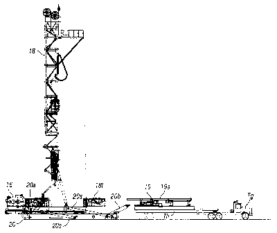
Figures 4A to 4E illustrate a method in accordance
with the present invention for the installation of a
centre floor section 19.
As shown in Figure 4A, the braces 12i, 12j have been
released from the parts 12d, 12e, respectively, pivoted
on their respective connections 12k, 12m; and moved out
CA 02716749 2012-05-09
- 15-
of the way. As shown in Figure 4B, the base box beam 14d
has been released from its connection 14k; pivoted on its
connection 14i; and moved out of the way.
As shown in Fig. 4C, a truck Tg with a trailer Th
supporting a centre floor section 19 has moved the centre
floor section 19 adjacent the substructure 20 (with the
mast already raised as described above). The
centre
floor section 19, optionally, includes a rotary table
19a. As shown in Fig. 4D, the truck Tg moves the centre
floor section 19 between the parts of the upper box 14
and base box 12 and the centre floor section 19 is
connected to the upper box 14, and may be connected to
lugs 12q,r,s,t,x,y. The upper box 12 comprising the side
side floor sections 12a and 12b are raised a small
distance using the substructure raising cylinder
apparatus 14f, 14g to lift the centre floor section 19
from the trailer Th of the truck Tg. The truck Tg and
trailer Th are moved away. The braces 12i, 12j are then
reconnected (see Fig. 4E). Such methods according to the
present invention for installing a mast (as in Figs. 3A-
3D) and then installing a centre floor section (as in
Figs. 4A-4D) permit the mast components to be transported
to the installation site on a truck at a height
sufficiently low to meet transportation height
requirements (the mast arriving at an installation site
at a height below substructure floor level). Thus the
mast, in such installation procedures, need not be lifted
above a substructure floor for installation.
Figures 5A to 5D illustrate the installation of a
rig structure (for example, house, cabin, control room,
doghouse, driller cabin) on the substructure 20. It is
within the scope of the present invention to use any
CA 02716749 2012-05-09
- 16-
known apparatus and method for installing a rig structure
on the substructure. Alternatively, the rig structure
(for example, a doghouse 17) is installed on the
substructure 20 in a method described in PCT Application
Number PCT/GB2009/050070.
As shown in Figures 5A to 5C, the doghouse 17
supported on a trailer Tj of a truck Ti is moved into
position adjacent the substructure 20 and the
substructure 20 has been lowered. The
doghouse 17 is
connected to the substructure 20 and the truck Ti and
trailer Tj are then moved away (Figure 5D).
Figures 6A to 6D illustrate the raising of the
substructure 20 to move the rig 10 into a working
position.
As shown in Figure 6A, the substructure 20 is
lowered or remains in a lowered position to install
drawworks skid support legs 16a; various equipment and
apparatuses; for example, (see Figure 6F) an iron
roughneck 24; air tugger winches 25a; an independent
rotary drive 25b; and a rotary table 25c (if not already
installed) over a well centre WC and near a mousehole MH
(any of which optionally may be installed on the centre
section before installation on the substructure); and
other equipment and hand rails.
As shown in Figure 68, the substructure 20 is raised
using the substructure raising cylinder apparatuses 20a
raising the upper box 12, which has the mast 18, and the
other equipment fixed thereto. A bottom end of each of
the legs 16a is pinned to the base box 14 to provide
additional support to the drawworks 16.. The base box
beams 14d and 14e are pivoted and reconnected to the
connections 14k, 14m, respectively. A BOP support beam
CA 02716749 2012-05-09
- 17-
structure 14s is connected to the base box 14. Support
legs 14t have a top end rotatably connected to and depend
from lugs 14v and are connected at their lower ends to
lugs 14w on the base box 14between the upper box 12 and
the base box 14 when the upper box 12 has been raised to
operating height. If the mast 18 is a telescoping mast,
the mid mast section 18b is telescoped up from the bottom
mast section 18a (Figure 6C). As shown in Figure 6D the
rig 10 is erected and, optionally, a rig walker 28 (to
facilitate rig movement) is installed on the base box 14.
Figure 6F is a top view of the upper box 12 with the
drawworks 16, doghouse 17, and centre floor 19 installed.
Figures 7A to 7F illustrate structure for connection
of various parts of the rig as in Figure 6F; shown with a
drawworks deleted.
Figures 7A to 7F illustrate various connection
structures both before the centre floor 19 is installed
and after the centre floor 19 is installed.
Figures 7B to 7C illustrate the connection of beams
B1 and B2 with pins Pa.
Figures 7D to 7E illustrate the connection of parts
P1 and P2.
Figures 7G to 7F illustrate the connection of parts
P3 and P4.
Figures 7H - 71 illustrate the connection of parts
P5 and P6.
The present invention, therefore, provides in some,
but not in necessarily all, embodiments a method for
assembling a drilling rig, the method including:
assembling a substructure of a drilling rig, the assembly
including connecting an upper box to a lower box, the
upper box having an upper open space, the lower box
CA 02716749 2012-05-09
- 18-
having a lower open space, and the upper open space above
the lower open space; moving with a vehicle on ground a
floor section connected to and supported by the vehicle
into open space including the upper open space and the
lower open space; and securing the floor section to the
substructure. Such a method may one or some, in any
possible combination, of the following: disconnecting the
floor section from the vehicle, and moving the vehicle
away from the drilling rig; installing a drawworks (or
rig apparatus) on the substructure; assembling a mast
connected to the substructure; erecting the mast on the
substructure; installing a rig structure on the
substructure; wherein the rig structure is one of
doghouse, cabin, and control room; installing rig
equipment on the substructure; wherein the rig equipment
is one of winch, iron roughneck, independent rotary table
drive, and rotary table; and/or raising with raising
apparatus the substructure to an operational height.
The present invention, therefore, provides in some,
but not in necessarily all, embodiments a method for
assembling a drilling rig, the method including:
assembling a substructure of a drilling rig, the assembly
including connecting an upper box to a lower box, the
upper box having an upper open space, the lower box
having a lower open space, and the upper open space above
the lower open space; moving with a vehicle on ground a
floor section connected to and supported by the vehicle
into open space including the upper open space and the
lower open space; and securing the floor section to the
substructure; disconnecting the floor section from the
vehicle; moving the vehicle away from the drilling rig;
installing a drawworks (or rig apparatus) on the
CA 02716749 2012-05-09
- 19-
=
substructure; assembling a mast connected to the
substructure; erecting the mast on the substructure;
installing a rig structure on the substructure; and
raising with raising apparatus the substructure to an
operational height.
The present invention, therefore, provides in some,
but not in necessarily all, embodiments a system for
drilling including: a substructure, the substructure
locatable on ground and including an upper box to a lower
box, the upper box having an upper open space, the lower
box having a lower open space, and the upper open space
above the lower open space; a floor section, the floor
section movable with a vehicle on ground adjacent the
substructure, the floor section connected to and
supported by the vehicle and movable on the vehicle into
an open space including the upper open space and the
lower open space; and the floor section releasably
connected to the substructure. Such a system may one or
some, in any possible combination, of the following: a
drawworks (or rig apparatus) on the substructure; a mast
connected to the substructure; a rig structure on the
substructure; wherein the rig structure is one of
doghouse, cabin, and control room; rig equipment on the
substructure; wherein the rig equipment is one of winch,
iron roughneck, independent rotary table drive, and
rotary table; and/or raising apparatus connected to the
substructure for raising the substructure to an
operational height.
The present invention, therefore, provides in some,
but not in necessarily all, embodiments a substructure
for a drilling rig, the substructure including: an upper
box with an upper open space; a lower box with a lower
CA 02716749 2012-05-09
- 20-
open space; the upper open space above the lower open
space and comprising a substructure space; the
substructure space sized for selective receipt therein of
a vehicle; and a floor section connectible to and
supportable by the vehicle for movement into the
substructure space, the floor section connected to the
substructure.