Language selection

Search

Patent 2716775 Summary

Third-party information liability

Some of the information on this Web page has been provided by external sources. The Government of Canada is not responsible for the accuracy, reliability or currency of the information supplied by external sources. Users wishing to rely upon this information should consult directly with the source of the information. Content provided by external sources is not subject to official languages, privacy and accessibility requirements.

Claims and Abstract availability

Any discrepancies in the text and image of the Claims and Abstract are due to differing posting times. Text of the Claims and Abstract are posted:

  • At the time the application is open to public inspection;
  • At the time of issue of the patent (grant).
(12) Patent: (11) CA 2716775
(54) English Title: INTERNALLY DAMPENED PERCUSSION ROCK DRILL
(54) French Title: PERFORATEUR MECANIQUE A PERCUSSION AMORTIE EN INTERNE
Status: Granted and Issued
Bibliographic Data
(51) International Patent Classification (IPC):
  • E21B 04/14 (2006.01)
  • B23B 47/00 (2006.01)
  • B25D 09/00 (2006.01)
(72) Inventors :
  • PATTERSON, WILLIAM N. (United States of America)
  • PATTERSON, GLENN (United States of America)
(73) Owners :
  • WILLIAM N. PATTERSON
  • GLENN PATTERSON
(71) Applicants :
  • WILLIAM N. PATTERSON (United States of America)
  • GLENN PATTERSON (United States of America)
(74) Agent: MOFFAT & CO.
(74) Associate agent:
(45) Issued: 2013-09-17
(86) PCT Filing Date: 2009-03-06
(87) Open to Public Inspection: 2009-09-11
Examination requested: 2010-08-30
Availability of licence: N/A
Dedicated to the Public: N/A
(25) Language of filing: English

Patent Cooperation Treaty (PCT): Yes
(86) PCT Filing Number: PCT/US2009/036312
(87) International Publication Number: US2009036312
(85) National Entry: 2010-08-30

(30) Application Priority Data:
Application No. Country/Territory Date
12/150,908 (United States of America) 2008-05-01
61/034,472 (United States of America) 2008-03-06

Abstracts

English Abstract


A percussion drill, and methods of using the same, including a shank in
mechanical alignment with a piston- hammer
and a valve in fluid communication with the piston- hammer. The percussion
drill further includes an internal hydraulic
dampening system for reducing the velocity of the piston-hammer when the shank
is forward of a power position relative to the
velocity of the piston-hammer when the shank is in a power position.
Preferably, the internal hydraulic dampening system includes
mechanical alignment of a portion of the piston-hammer with a port in fluid
communication with the valve, operable to reduce
fluid flow into an area surrounding the valve when the piston-hammer is
forward of its position relative to its normal operation.


French Abstract

La présente invention concerne un perforateur mécanique et des procédés pour son utilisation, comprenant un emmanchement intérieur en alignement mécanique avec un piston-marteau et une soupape en communication fluidique avec le piston-marteau. Le perforateur mécanique comprend en outre un système damortissement hydraulique interne pour réduire la vitesse du piston-marteau lorsque lemmanchement se trouve dans une position motrice. De préférence, le système damortissement hydraulique interne comprend un alignement mécanique dune partie du piston-marteau avec un orifice en communication fluidique avec la soupape, pouvant être actionné pour réduire lécoulement de fluide dans une région entourant la soupape lorsque le piston-marteau est avant de sa position par rapport à son fonctionnement normal.

Claims

Note: Claims are shown in the official language in which they were submitted.


WHAT IS CLAIMED IS:
1. A percussion drill comprising:
a shank movable between a power position and a
position forward of the power position;
a valve in fluid communication with the piston-hammer,
wherein the piston-hammer includes a trip section having a
forward shoulder, a center area and a back shoulder, the center
area having a smaller diameter than the diameter of the forward
and back shoulders forming a high pressure fluid communication
path from a third port to a second port; and
an internal hydraulic dampening system comprising the
back shoulder movable at least partially over the second port and
configured to decrease the high pressure fluid flow from the
third port into the second port for reducing the fluid flow to
the valve in response to the shank being forward of the power
position relative to the fluid flow to the valve when the shank
is in the power position to thereby slow movement of the valve
when the piston-hammer travels forward of the power position and
thereby reduce the frequency of impact blows when the shank is
forward of the power position.
2. The percussion drill of Claim 1, wherein the
piston-hammer is disposed within a first housing having at least
a first port, the second port, the third port, a fourth port and
the valve is disposed within a second housing having at least a
fifth port, a sixth port, and a seventh port;
the piston-hammer further including a front landing
and a rear landing and wherein the fluid communication between
the valve and piston-hammer includes fluid communication between
the ports of the first and second housings.
3. The percussion drill of Claim 1, wherein the fluid
used in the fluid communication is selected from the group
consisting of water, oil, glycol, and invert emulsions, having
a pressure of at least about 68 atm.
-9-

4. The percussion drill of Claim 1, wherein the fluid
used in the fluid communication is hydraulic oil having a
pressure of about 170 atm.
5. The percussion drill of Claim 1, wherein the
piston-hammer further includes a front landing and a rear
landing, and wherein the internal hydraulic dampening system
includes mechanical alignment of the center area and back
shoulder of the trip section with the second port to reduce fluid
flow into the valve when the piston-hammer is forward of its
position relative to its normal operation.
6. The percussion drill of Claim 2, wherein the internal
hydraulic dampening system includes mechanical alignment of the
center area and back shoulder of the trip section with the second
port to reduce fluid flow into the second housing when the
piston-hammer is forward of its position relative to its normal
operation.
7. A method of actuating the piston-hammer of the
percussion drill of Claim 2, comprising:
aligning the center area until it bridges the second
and third ports;
permitting fluid flow into the seventh port;
causing the valve to move in a direction toward the shank
within the second housing;
increasing the force acting on the piston-hammer until it
moves away from the shank; and
continuing to move the piston-hammer until the forward
shoulder blocks fluid flow into the second port.
8. The method of Claim 7, further comprising:
moving the valve in a direction away from the shank
until it blocks fluid flow between the sixth port and the first
port;
-10-

permitting fluid flow between the fifth port and the
first port; and
causing the piston-hammer to stop.
9. The method of Claim 8, further comprising:
increasing the pressure differential within the first
housing against the piston-hammer until the piston-hammer moves
toward the shank, wherein the force differential is at least
about 111 newtons;
moving the valve toward the shank;
permitting fluid flow into the first port; and
moving the piston-hammer toward the shank.
10. The method of Claim 9, wherein the steps are repeated
at least 2500 times in one minute.
11. A method of internally dampening the piston-hammer of
the percussion drill of Claim 2, comprising:
moving the shank forward, out of power position;
aligning the back shoulder with the second port to
impede at least a portion of the fluid flow through the second
port;
reducing fluid flow into the seventh port, slowing the
movement of the valve toward the shank; and
moving the trip section of the piston-hammer into a
dash pot, causing the movement of the piston-hammer to slow.
12. The method of claim 11, wherein the dash pot contains
high pressure fluid in constant fluid communication with the
forward landing.
13. The method of Claim 11, wherein the impediment caused
by the back shoulder causes at least a 20 percent decrease in
fluid flow into the seventh port preferably at least a 70 percent
decrease.
-11-

14. The method of Claim 11, further comprising:
moving the back shoulder until it blocks fluid flow
into the second port;
causing the valve to move in a direction toward the
shank;
holding the valve in a position within the second
housing;
causing continuous fluid flow into the first port; and
holding the piston-hammer in a position within the
first housing.
15. A percussion drill comprising:
a first housing having a shank in mechanical alignment
with a piston-hammer, the shank and piston-hammer movable between
a power position and a position forward of a power position;
a second housing in fluid communication with the first
housing, the second housing having a valve; and
a dampening system reducing fluid flow from the first
housing to the second housing in response to the shank and
piston-hammer being forward of the power position relative to the
fluid flow to the second housing when the shank and piston-hammer
are in the power position.
16. The percussion drill of Claim 15, wherein the
dampening system includes a trip section disposed on the piston
hammer forming a high pressure fluid communication path between
a pair of fluid ports, the trip section movable at least
partially over one of the ports decreasing the fluid flow to the
valve in response to the shank and piston-hammer being forward
of the power position.
17. The percussion drill of Claim 15, wherein the
dampening system includes a trip section having a forward
shoulder, a center area and a back shoulder, the center area
having a smaller diameter than the diameter of the forward and
-12-

back shoulders forming the high pressure fluid communication path
between a pair of fluid ports.
18. The percussion drill of Claim 17, wherein the back
shoulder is movable at least partially over one of the ports to
decrease the high pressure fluid flow to the valve.
19. The percussion drill of any one of Claims 15 to 18,
wherein the fluid is selected from the group consisting of water,
oil, glycol, and invert emulsions, having a pressure of at least
about 68 atm.
20. The percussion drill of any one of Claims 15 to 18,
wherein the fluid is hydraulic oil having a pressure of about 170
atm.
21. The percussion drill of any one of Claims 15 to 20,
wherein the back shoulder is moveable at least partially over one
of the ports to decrease the high pressure fluid flow into the
valve.
22. The percussion drill of Claims 15 to 20, wherein the
piston-hammer is disposed within a first housing having at least
a first port, a second port, a third port, a fourth port and the
valve is disposed within a second housing having at least a fifth
port, a sixth port, and a seventh port;
the piston-hammer having a front landing, a trip
section, and a rear landing and wherein fluid communication
between the valve and piston-hammer includes fluid communication
between the ports of the first housing and second housing.
23. A percussion drill comprising:
a shank movable between a power position and a
position forward of the power position;
-13-

a valve in fluid communication with a piston-hammer;
and
an internal hydraulic dampening system including a
trip section disposed on the piston hammer forming a high
pressure fluid communication path between a pair of fluid ports,
the trip section movable at least partially over one of the ports
decreasing the fluid flow to the valve in response to the shank
and piston-hammer being forward of the power position relative
to the fluid flow to the valve when the shank and piston-hammer
are in the power position to thereby slow movement of the valve
and reduce the frequency of impact blows when the shank and
piston-hammer are forward of the power position.
24. The percussion drill of Claim 23, wherein the trip
section comprises a forward shoulder, a center area and a back
shoulder, the center area having a smaller diameter than the
diameter of the forward and back shoulders forming the high
pressure fluid communication path between the pair of fluid
ports.
25. The percussion drill of Claim 23, wherein the trip
section comprises a forward shoulder, a center area and a back
shoulder, wherein the back shoulder is movable at least partially
over one of the ports to decrease the high pressure fluid flow
to the valve.
26. The percussion drill of Claim 23, wherein the piston
hammer is disposed within a first housing having at least a first
port, a second port, a third port, a fourth port and the valve
is disposed within a second housing having at least a fifth port,
a sixth port and a seventh port, wherein the fluid communication
between the valve and piston-hammer includes fluid communication
between the ports of the first and second housings.
-14-

27. The percussion drill of Claim 23, wherein the fluid
used in the fluid communication is selected from the group
consisting of water, oil, glycol, and invert emulsions, having
a pressure of at least about 68 atm.
28. The percussion drill of Claim 23, wherein the fluid
used in the fluid communication is hydraulic oil having a
pressure of about 170 atm.
29. A method of actuating the piston-hammer of the
percussion drill of Claim 26, comprising:
aligning the center area until it bridges the second
and third ports;
permitting fluid flow into the seventh port;
causing the valve to move in a direction toward the
shank within the second housing;
increasing the force acting on the piston-hammer until
it moves away from the shank; and
continuing to move the piston-hammer until the forward
shoulder blocks fluid flow into the second port.
30. The method of Claim 29, further comprising:
moving the valve in a direction away from the shank
until it blocks fluid flow between the sixth port and the first
port;
permitting fluid flow between the fifth port and the
first port; and
causing the piston-hammer to stop.
31. The method of Claim 29 or 30, further comprising:
increasing the pressure differential within the first
housing against the piston-hammer until the piston-hammer moves
toward the shank, wherein the force differential is at least
about 111 newtons;
moving the valve toward the shank;
-15-

permitting fluid flow into the first port; and
moving the piston-hammer toward the shank.
32. The method of any one of Claims 29 to 31, wherein the
steps are repeated at least 2500 times in one minute.
33. A method of internally dampening the piston-hammer of
the percussion drill of Claim 26, comprising:
moving the shank forward, out of power position;
aligning the back shoulder with the second port to
impede at least a portion of the fluid flow through the second
port;
reducing fluid flow into the seventh port, slowing the
movement of the valve toward the shank; and
moving the trip section of the piston-hammer into a
dash pot, causing the movement of the piston-hammer to slow.
34. The method of Claim 33, wherein the dash pot contains
high pressure fluid in constant fluid communication with the
forward landing.
35. The method of Claim 33 or 34, wherein the impediment
caused by the back shoulder causes at least a 20 percent decrease
in fluid flow into the seventh port, preferably at least a 70
percent decrease.
36. The method of any one of Claims 33 to 35, further
comprising:
moving the back shoulder until it blocks fluid flow
into the second port;
causing the valve to move in a direction toward the
shank;
holding the valve in a position within the second
housing;
causing continuous fluid flow into the first port; and
-16-

holding the piston-hammer in a position within the
first housing.
37. A percussion drill comprising:
a shank aligned with a piston-hammer, the shank
movable between a power position and a position forward of the
power position,
wherein the piston hammer and shank are disposed
within a first housing having a first port, a second port, a
third port and a fourth port and the piston-hammer comprises a
front landing, a rear landing and a trip section, the trip
section having a center area disposed between a forward shoulder
and a back shoulder, the center area having a smaller diameter
than the diameter of the forward and back shoulders and disposed
within the first housing forming a high pressure fluid path
between the third and second ports;
a valve disposed in a second housing in fluid
communication with the piston-hammer; and
an internal hydraulic dampening system comprising at
least the back shoulder movable over the second port and
configured to decrease the high pressure fluid flow from the
third port to the second housing in response to the shank and
piston-hammer being forward of the power position.
-17-

Description

Note: Descriptions are shown in the official language in which they were submitted.


CA 02716775 2011-06-20
INTERNALLY DAMPENED PERCUSSION ROCK DRILL
FIELD OF THE INVENTION
[0002] The present invention pertains to a pressure fluid
actuated reciprocating piston-hammer percussion rock drill
including an internal dampening system for reducing the power
output of the piston-hammer when the shank is forward of the
impact position.
BACKGROUND OF THE INVENTION
[0003] In the art of pressure fluid actuated reciprocating
piston-hammer percussion rock drills and similar percussion
tools, it is known to provide the general configuration of the
tool to include a sliding sleeve type valve for distributing
pressure fluid to effect reciprocation of a fluid actuated
piston-hammer. There are many applications of these types of
drills including, for example, drilling holes having a
diameter ranging from about 4 centimeters to about 30
centimeters.
[0004] Examples of such drills are generally disclosed and
claimed in U.S. Pat. No. 5,680,904, issued Oct. 28, 1997. The
percussion rock drill disclosed in the '904 patent includes
opposed sleeve type valves disposed on opposite reduced
diameter end portions of the reciprocating piston-hammer,
respectively, for movement with the piston-hammer and for
movement relative to the piston-hammer to distribute pressure
fluid to opposite sides of the piston-hammer to effect
reciprocation of same. Another advantageous design of a fluid
actuated percussion rock drill is disclosed and
-1-

CA 02716775 2010-08-30
WO 2009/111690
PCT/US2009/036312
claimed in U.S. Patent 4,828,048 to James R. Mayer and
William N. Patterson. The drill described and claimed in
the '048 patent utilizes a single sleeve type distributing
valve disposed at the fluid inlet end of the drill cylinder.
[0005] In such drills the shank may be moved forward, out of
its power position, when drilling is no longer required.
Such is the situation when the drill is being pulled out of
the hole. During
this time, however, the sliding sleeve
type valve permits the high pressure fluid to continuously
drive the piston-hammer. Accordingly, unless impeded, a
front landing of the piston-hammer will strike the forward
moved shank. Moreover, as the shank is moved forward there
is additional length in which the piston-hammer may gain
speed. Thus, in some cases the front landing of the piston-
hammer strikes the forward moved shank with a force greater
than that experienced during operational drilling. Such
excessive impact causes components such as the shank to wear
unnecessarily. Accordingly, it is desirable to reduce or
eliminate such excessive impact. Prior methods of doing so
having included the use of shock absorbers, cushions and/or
springs to absorb the energy of the piston-hammer. These
devices and methods, however, wear themselves and require
replacement.
[0006] Therefore, what is needed is an improved internal
dampening system that is wear resistant.
BRIEF SUMMARY OF THE INVENTION
[0010] The present invention provides an improved
pressure fluid actuated reciprocating piston-hammer
percussion tool, particularly adapted for rock drilling.
The invention contemplates, in particular, the provision of
an internal dampening system for reducing the velocity of
the piston-hammer when the shank is forward of a power
-2-

CA 02716775 2012-11-16
position relative to the velocity of the piston-hammer when the
shank is in a power position.
[0011] In another important aspect of the present invention
the piston-hammer includes a front landing, a trip section, and
a rear landing; the trip section has a forward shoulder, a center
area, and a back shoulder; and the center area is of a lesser
diameter than the diameter of the forward shoulder and back
shoulder.
[0012] In a still further important aspect of the present
invention, the fluid communication between the valve and
piston-hammer includes at least a first and second port; the
internal hydraulic dampening system includes mechanical alignment
of the center area and back shoulder of the trip section with the
second port to reduce fluid flow into the valve when the
piston-hammer is forward of its position relative to its normal
operation.
[0012a] In accordance with another aspect, there is provided
a percussion drill comprising: a shank movable between a power
position and a position forward of the power position; a
valve in fluid communication with the piston-hammer, wherein the
piston-hammer includes a trip section having a forward shoulder,
a center area and a back shoulder, the center area having a
smaller diameter than the diameter of the forward and back
shoulders forming a high pressure fluid communication path from
a third port to a second port; and an internal hydraulic
dampening system comprising the back shoulder movable at least
partially over the second port and configured to decrease the
high pressure fluid flow from the third port into the second port
for reducing the fluid flow to the valve in response to the shank
being forward of the power position relative to the fluid flow
to the valve when the shank is in the power position to thereby
slow movement of the valve when the piston-hammer travels forward
-3-

CA 02716775 2012-11-16
of the power position and thereby reduce the frequency of impact
blows when the shank is forward of the power position.
[0012b] In accordance with a further aspect, there is provide
a method of actuating the piston-hammer of the percussion drill
described in paragraph 0012b above, wherein the piston-hammer is
disposed within a first housing having at least a first port, the
second port, the third port, a fourth port and the valve is
disposed within a second housing having at least a fifth port,
a sixth port, and a seventh port; the piston-hammer further
including a front landing and a rear landing and wherein the
fluid communication between the valve and piston-hammer includes
fluid communication between the ports of the first and second
housings, the method comprising: aligning the center area until
it bridges the second and third ports; permitting fluid flow
into the seventh port; causing the valve to move in a direction
toward the shank within the second housing; increasing the force
acting on the piston-hammer until it moves away from the shank;
and continuing to move the piston-hammer until the forward
shoulder blocks fluid flow into the second port.
[0012c] In accordance with yet another aspect, there is
provided A method of internally dampening the piston-hammer of
the percussion drill described in paragraph 0012b above, wherein
the piston-hammer is disposed within a first housing having at
least a first port, the second port, the third port, a fourth
port and the valve is disposed within a second housing having at
least a fifth port, a sixth port, and a seventh port; the
piston-hammer further including a front landing and a rear
landing and wherein the fluid communication between the valve and
piston-hammer includes fluid communication between the ports of
the first and second housings, the method comprising: moving the
shank forward, out of power position; aligning the back shoulder
with the second port to impede at least a portion of the fluid
flow through the second port; reducing fluid flow into the
-3a-

= CA 02716775 2012-11-16
seventh port, slowing the movement of the valve toward the shank;
and moving the trip section of the piston-hammer into a dash pot,
causing the movement of the piston-hammer to slow.
[0012d] In accordance with a still further aspect, there is
provided a percussion drill comprising: a first housing having
a shank in mechanical alignment with a piston-hammer, the shank
and piston-hammer movable between a power position and a position
forward of a power position; a second housing in fluid
communication with the first housing, the second housing having
a valve; and a dampening system reducing fluid flow from the
first housing to the second housing in response to the shank and
piston-hammer being forward of the power position relative to the
fluid flow to the second housing when the shank and piston-hammer
are in the power position.
[0012e] In accordance with another aspect, there is provided
a percussion drill comprising: a shank movable between a power
position and a position forward of the power position; a valve
in fluid communication with a piston-hammer; and an internal
hydraulic dampening system including a trip section disposed on
the piston hammer forming a high pressure fluid communication
path between a pair of fluid ports, the trip section movable at
least partially over one of the ports decreasing the fluid flow
to the valve in response to the shank and piston-hammer being
forward of the power position relative to the fluid flow to the
valve when the shank and piston-hammer are in the power position
to thereby slow movement of the valve and reduce the frequency
of impact blows when the shank and piston-hammer are forward of
the power position.
[00].2f] In accordance with a further aspect, there is provided
a method of actuating the piston-hammer of the percussion drill
described in paragraph 0012e above, wherein the piston hammer is
disposed within a first housing having at least a first port, a
-3b-

CA 02716775 2012-11-16
second port, a third port, a fourth port and the valve is
disposed within a second housing having at least a fifth port,
a sixth port and a seventh port, wherein the fluid communication
between the valve and piston-hammer includes fluid communication
between the ports of the first and second housings, the method
comprising: aligning the center area until it bridges the second
and third ports; permitting fluid flow into the seventh port;
causing the valve to move in a direction toward the shank within
the second housing; increasing the force acting on the
piston-hammer until it moves away from the shank; and continuing
to move the piston-hammer until the forward shoulder blocks fluid
flow into the second port.
[0012g] In accordance with a another aspect, there is provided
a method of internally dampening the piston-hammer of the
percussion drill described in paragraph 0012e above, wherein the
piston hammer is disposed within a first housing having at least
a first port, a second port, a third port, a fourth port and the
valve is disposed within a second housing having at least a fifth
port, a sixth port and a seventh port, wherein the fluid
communication between the valve and piston-hammer includes fluid
communication between the ports of the first and second housings,
the method comprising: moving the shank forward, out of power
position; aligning the back shoulder with the second port to
impede at least a portion of the fluid flow through the second
port; reducing fluid flow into the seventh port, slowing the
movement of the valve toward the shank; and moving the trip
section of the piston-hammer into a dash pot, causing the
movement of the piston-hammer to slow.
[0012h] In accordance with yet another aspect, there is
provided a percussion drill comprising: a shank aligned with a
piston-hammer, the shank movable between a power position and a
position forward of the power position, wherein the piston hammer
and shank are disposed within a first housing having a first
-3c-

CA 02716775 2012-11-16
port, a second port, a third port and a fourth port and the
piston-hammer comprises a front landing, a rear landing and a
trip section, the trip section having a center area disposed
between a forward shoulder and a back shoulder, the center area
having a smaller diameter than the diameter of the forward and
back shoulders and disposed within the first housing forming a
high pressure fluid path between the third and second ports; a
valve disposed in a second housing in fluid communication with
the piston-hammer; and an internal hydraulic dampening system
comprising at least the back shoulder movable over the second
port and configured to decrease the high pressure fluid flow from
the third port to the second housing in response to the shank and
piston-hammer being forward of the power position.
[0013] Those skilled in the art will further appreciate the
above-mentioned features and advantages of the invention together
with other superior aspects thereof upon reading the detailed
description which follows in conjunction with the drawing.
BRIEF DESCRIPTION OF THE SEVERAL VIEWS OF THE DRAWINGS
[0014] The drawing figures are not necessarily to scale and
certain features of the invention may be shown exaggerated in
scale or in somewhat schematic form in the interest of clarity
and conciseness, wherein:
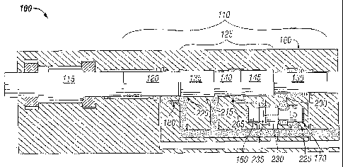
[0015] FIGURE 1 is a schematic view of a piston-hammer in
contact with a shank while the shank is in a power position;
[0016] FIGURE 2 is a schematic view of the piston-hammer
moving away from the shank while the shank is in a power
position;
-3d-

CA 02716775 2010-08-30
WO 2009/111690
PCT/US2009/036312
[0 0 1 7 ] FIGURE 3
is a schematic view of the piston-hammer
moving toward the shank while the shank is in a power
position;
[0018] FIGURE 4
is a schematic view of the piston-hammer
moving toward the shank while the shank is out of a power
position;
[0019] FIGURE 5
is a schematic view of the piston-hammer
moving at a forward most point while the shank is out of a
power position; and
[0020] FIGURE 6
is a schematic view of the piston-hammer
moving and shank in an intermediate position.
DETAILED DESCRIPTION OF THE INVENTION
[0021] In the
description which follows like parts are
marked throughout the specification and drawing with the
same reference numerals, respectively. The drawing figures
are not necessarily to scale and certain features of the
invention may be shown exaggerated in scale or in somewhat
schematic form in the interest of clarity and conciseness.
[0022]
Referring to FIG. 1, there is illustrated a
schematic of one preferred embodiment of a percussion drill
100. The percussion drill 100 preferably includes a piston-
hammer 110 and a shank 115 in mechanical alignment
therewith, as well as a valve 150 in fluid communication
with the piston-hammer 110. The
piston-hammer 110
preferably includes a front landing 120, a trip section 125,
and a rear landing 130. And, the trip section 125 itself
preferably includes a front shoulder 135 a center area 140
and a back shoulder 145. Preferably, the piston-hammer 110
and its component segments are cylindrical. Preferably, the
front shoulder 135 and the back shoulder 145 are of a
substantially uniform diameter, and the center area 140 is
of a smaller diameter as compared to the front shoulder 135
-4-

CA 02716775 2010-08-30
WO 2009/111690
PCT/US2009/036312
and back shoulder 145. In an embodiment, the front shoulder
135 and the back shoulder 145 are of a substantially uniform
height, and the center area 140 is of a smaller height as
compared to the front shoulder 135 and back shoulder 145.
[0023] The
piston-hammer 110 is disposed within a first
housing 160, and the valve 150 is disposed within a second
housing 170. The housings may be of any shape. In a
preferred embodiment, the first housing 160 has at least a
first port 200, a second port 205, a third port 215, and a
fourth port 220 and the second housing has at least a fifth
port 225, a sixth port 230, and a seventh port 235. The
ports serve to allow fluid flow, preferably high pressure
fluid, to enter and exit the housings and drive the piston-
hammer 110 and valve 150.
[0024] The high
pressure fluid may be water, oil, glycol,
invert emulsions, and the like fluids of at least about 170
atm. In various embodiments, the high pressure fluid may be
at least about 68 atm, alternatively at least about 136 atm,
alternatively at least about 204 atm, alternatively at least
about 272 atm, and alternatively at least about 340 atm.
Preferably, the high pressure fluid is hydraulic oil at
about 170 atm.
[0025] FIGs. 1,
2, and 3 illustrate the shank 115 in a
normal or power position. FIGs. 4
and 5 illustrate the
shank 115 outside of its normal or power position. FIG. 6
illustrates the shank in an intermediate position.
[0026]
Continuing with reference to FIG. 1, the piston-
hammer 110 is at its forward most position and the front
landing 120 is in contact with the shank 115. The
center
area 140 of the trip section 125 bridges the second 205 and
third 215 ports allowing fluid to flow into the seventh port
235. The fluid flow into the seventh port 235 increases the
pressure differential within the valve 150 and causes it to
-5-

CA 02716775 2010-08-30
WO 2009/111690
PCT/US2009/036312
move in a direction toward the shank 115 within the second
housing 170. At the same time, the piston-hammer 110 moves
away from the shank 115. As the trip section 125 moves away
from the shank 115 the center area 140 no longer bridges the
second 205 and third 215 ports, and fluid is cut off from
the second port 205.
[0027]
Referring to FIG. 2, the movement of the valve 150
in a direction away from the shank 115 blocks the fluid flow
between the sixth port 230 and the first port 200. The
movement of the valve 150 in a direction away from the shank
115 opens the fluid flow between fifth port 225 and the
first port 200. This will slow the movement of the piston-
hammer 110 until it comes to a stop.
Thereafter, the
pressure differential within the first housing 160 against
the piston-hammer 110 will cause the piston-hammer 110 to
move toward from the shank 115, as shown in FIG. 3. In an
embodiment, the force differential sufficient to actuate the
piston-hammer 110 is at least about 111 newtons, preferably
the force differential is at least about 222 newtons. In an
embodiment, the force differential sufficient to actuate the
piston-hammer 110 is at least about 2.22 kilonewtons.
[0028]
Referring to FIG. 3, the movement of the valve 150
toward the shank 115 allows fluid to flow into the first
port 200. When the
pressure differential between the rear
landing 130 of the piston-hammer 110 and the front landing
120 of the piston-hammer 110 is great enough, the piston-
hammer 110 will move toward the shank 115. The process will
then repeat.
Preferably, piston-hammer 110 impacts the
shank 115 at least 2500 times in one minute.
[0029]
Referring to FIG. 4, the shank 115 is moved
forward, and out of normal striking position, as shown with
respect to FIG. 1. In this
forward position, however, the
back shoulder 145 of the trip section 125 impedes at least a
-6-

CA 02716775 2012-11-16
portion of the fluid flow through the second port 205. The
impediment caused by the back shoulder 145 of the trip section
125 preferably decreases the fluid flow into the seventh port 235
in an amount sufficient to slow the movement of the valve 150
toward the shank 115. In this embodiment, the valve 150 moves
more slowly toward the shank 115 than in power operation. By
movement of front shoulder 135 of the trip section 125 into a
dash pot 180, i.e., a restricted fluid area, the forward movement
of the piston-hammer 110 is slowed.
[0030] In an embodiment, the back shoulder 145 causes at
least a 10 percent decrease in the fluid flow into the seventh
port 235. In an alternative embodiment, the back shoulder 145
causes at least a 20 percent decrease in the fluid flow into the
seventh port 235. In preferred embodiment, the back shoulder 145
causes at least a 50 percent decrease in the fluid flow into the
seventh port 235. In a still further preferred embodiment, the
back shoulder 145 causes at least a 70 percent decrease in the
fluid flow into the seventh port 235.
[0031] Referring to FIG. 5, the shank 115 is illustrated
forward of power position, and the piston-hammer 110 is in its
most forward position. In this manner, the back shoulder 145 of
the trip section 125 blocks fluid flow into the second port 205.
Thus, no fluid flows into the seventh port 235, and the valve 150
remains in its most rearward position, or is alternatively moved
to its most rearward forward position. In either event, in this
position the valve 150 permits fluid to flow continuously into
the first port 200, and thus the piston-hammer 110 is held in its
most forward position.
[0032] Preferably, the dash pot 180 contains high pressure
fluid in constant fluid communication with the forward landing
120. Thus, the dash pot 180 serves to balance the pressure on the
-7-

. CA 02716775 2012-11-16
front seal between the front landing 120 and the front shoulder
135 of the trip shoulder 125.
[0033] Referring to FIG. 6, the shank 115 is pushed back into
power position. Accordingly, the fluid communication between the
third port 215 and the second port 205 is opened. Thus,
permitting the normal hammer oscillation to resume as described
above.
[0034] The construction and operation of the drill 100, and
associated parts, may be carried out using conventional materials
and engineering practices known to those skilled in the art of
hydraulic percussion rock drills and the like. Although preferred
embodiments of the invention have been described in detail
herein, those skilled in the art will recognize that various
substitutions and modifications may be made to the invention
without departing from the scope of the appended claims.
-8-

Representative Drawing
A single figure which represents the drawing illustrating the invention.
Administrative Status

2024-08-01:As part of the Next Generation Patents (NGP) transition, the Canadian Patents Database (CPD) now contains a more detailed Event History, which replicates the Event Log of our new back-office solution.

Please note that "Inactive:" events refers to events no longer in use in our new back-office solution.

For a clearer understanding of the status of the application/patent presented on this page, the site Disclaimer , as well as the definitions for Patent , Event History , Maintenance Fee  and Payment History  should be consulted.

Event History

Description Date
Common Representative Appointed 2019-10-30
Grant by Issuance 2013-09-17
Inactive: Cover page published 2013-09-16
Pre-grant 2013-06-20
Inactive: Final fee received 2013-06-20
Maintenance Request Received 2013-02-28
Notice of Allowance is Issued 2013-01-07
Letter Sent 2013-01-07
Notice of Allowance is Issued 2013-01-07
Inactive: Approved for allowance (AFA) 2012-12-18
Amendment Received - Voluntary Amendment 2012-11-16
Inactive: S.30(2) Rules - Examiner requisition 2012-05-22
Amendment Received - Voluntary Amendment 2012-04-03
Amendment Received - Voluntary Amendment 2011-06-20
Inactive: Cover page published 2010-12-03
Letter Sent 2010-10-27
Inactive: Acknowledgment of national entry - RFE 2010-10-27
Inactive: Inventor deleted 2010-10-27
Inactive: IPC assigned 2010-10-27
Application Received - PCT 2010-10-27
Inactive: First IPC assigned 2010-10-27
National Entry Requirements Determined Compliant 2010-08-30
Request for Examination Requirements Determined Compliant 2010-08-30
All Requirements for Examination Determined Compliant 2010-08-30
Small Entity Declaration Determined Compliant 2010-08-30
Application Published (Open to Public Inspection) 2009-09-11

Abandonment History

There is no abandonment history.

Maintenance Fee

The last payment was received on 2013-02-28

Note : If the full payment has not been received on or before the date indicated, a further fee may be required which may be one of the following

  • the reinstatement fee;
  • the late payment fee; or
  • additional fee to reverse deemed expiry.

Patent fees are adjusted on the 1st of January every year. The amounts above are the current amounts if received by December 31 of the current year.
Please refer to the CIPO Patent Fees web page to see all current fee amounts.

Owners on Record

Note: Records showing the ownership history in alphabetical order.

Current Owners on Record
WILLIAM N. PATTERSON
GLENN PATTERSON
Past Owners on Record
None
Past Owners that do not appear in the "Owners on Record" listing will appear in other documentation within the application.
Documents

To view selected files, please enter reCAPTCHA code :


To view images, click a link in the Document Description column (Temporarily unavailable). To download the documents, select one or more checkboxes in the first column and then click the "Download Selected in PDF format (Zip Archive)" or the "Download Selected as Single PDF" button.

List of published and non-published patent-specific documents on the CPD .

If you have any difficulty accessing content, you can call the Client Service Centre at 1-866-997-1936 or send them an e-mail at CIPO Client Service Centre.

({010=All Documents, 020=As Filed, 030=As Open to Public Inspection, 040=At Issuance, 050=Examination, 060=Incoming Correspondence, 070=Miscellaneous, 080=Outgoing Correspondence, 090=Payment})


Document
Description 
Date
(yyyy-mm-dd) 
Number of pages   Size of Image (KB) 
Abstract 2010-08-29 1 77
Drawings 2010-08-29 6 210
Claims 2010-08-29 4 128
Description 2010-08-29 8 316
Representative drawing 2010-12-02 1 31
Description 2011-06-19 10 404
Claims 2011-06-19 7 245
Description 2012-04-02 12 460
Claims 2012-04-02 9 323
Description 2012-11-15 12 475
Claims 2012-11-15 9 297
Representative drawing 2013-08-21 1 30
Maintenance fee payment 2024-02-05 38 1,541
Acknowledgement of Request for Examination 2010-10-26 1 189
Reminder of maintenance fee due 2010-11-08 1 113
Notice of National Entry 2010-10-26 1 233
Commissioner's Notice - Application Found Allowable 2013-01-06 1 163
PCT 2010-08-29 8 297
Fees 2011-02-28 1 44
Fees 2012-02-29 1 44
Fees 2013-02-27 1 46
Correspondence 2013-06-19 1 47