Note: Descriptions are shown in the official language in which they were submitted.
CA 02717595 2010-10-13
1
FLUID LOGIC TOOL FOR USE IN A SUBTERRANEAN WELL
BACKGROUND OF THE INVENTION
1. Field of the invention: This invention relates to downhole tools for oil
and gas
wells and similar applications and more particularly to servicing or
completing wells.
2. Brief Description of Prior Art: Many types of downhole tools are conveyed
into the
well for various types of applications in order to produce oil and gas from
underground
formations. As an example, typical downhole tools are packers, sliding
sleeves, ball
valves, flapper valves, and perforating guns, and gravel pack screens, to
mention a few.
Well formations may have one or more producing zones where each zone may need
a
series of tools such as a packer and a sliding sleeve and a gravel pack
screen. When
screens are run and positioned in a zone, this is commonly called a gravel
pack completion
or a frac pack completion and many varieties of downhole tool hookups exist.
Packers are typically used to create a seal between the I.D. of the casing to
the
O.D. of a production or completion string thus isolating producing formations.
Typically,
completion packers are set in the well bore by application of tubing pressure
through the
inside of a work string and setting tool. A ball may be dropped from the
surface and it
seats at a point below the setting tool, workstring pressure is applied, and
the setting tool
strokes to set the packer. A ball or ball seat can obstruct access the tools
below the packer.
Often it is attempted to recirculate the ball out of the hole. Sometimes a
plug is set in a
nipple below the packer so setting pressure can be applied to set the packer.
In this case,
the plug may have to be removed.
The current invention provides a means to maintain a full open I.D. through
the
completion.
Packers are also set on wireline or electric line where a Baker E-4 generates
sufficient pressure and force to set a packer, but this method is usually
limited to setting
sump packers or setting a single completion packer with minimal weight hanging
on the
bottom of the packer.
Intelligent well completions use some form of control line that is strapped to
the
O.D. of a completion string that hydraulically or electrically can generate
force to set
CA 02717595 2010-10-13
2
packers. This process can be very expensive and control lines are always
subject to some
type failure.
The present invention provides a new alternative to hydraulically set single
or
multiple packers in a single run without dropping balls or setting plugs.
Additionally the
same tool that sets the packers can be configured to unset packers or actuate
other tools
during a single trip into the hole.
Sliding sleeves are used to control the flow of fluid or slurry to or from a
formation
into the pipe string. Sliding sleeves, or frac sleeves, typically have
profiles on the inside of
the sleeves that allow mechanical shifting tools to engage the inside of the
sleeves so they
can be shifted open or closed. Sliding sleeves may be selectively shifted with
different
shifting tool key profiles such as the Otis standard and selective profiles
for the Model "B"
shifting tool. Other companies have varying key profiles for shifting sleeves
and shifting
tools.
The present invention allows one tool configuration to shift all sliding
sleeves
selectively or only shift, or actuate, one type of tool and not the other
tools.
The problem with shifting keys is that the shifting tools tend to jump out of
the
mating profiles for various reasons and shifting force is limited as a result.
Sliding sleeves
that have been downhole for extended periods of time tend to collect scale and
can become
difficult to shift. The present invention provides a means to apply a higher
force to shift
sliding sleeves where conventional methods tend to fail, especially in highly
deviated
wells. It is sometimes impossible to shift sliding sleeves in a deviated well
with wireline
because the deviation prevents the wireline shifting tool to reach the sliding
sleeve. Also,
it may be possible to reach sliding sleeves in a deviated well with coiled
tubing and a
shifting tool, but when the shifting tool engages the sliding sleeve; the drag
forces on the
coiled tubing through the bend limit the ability to shift the sliding sleeves.
The present invention does not create additional drag force on the coiled
tubing, so
the ease of moving coiled tubing through the bend is increased.
Also, the number of shifting tool key profiles and mating sliding sleeve
profiles is
limited, so shifting selectivity in multiple zones is also limited.
Furthermore, shifting tool
collets or keys sometimes break leaving unwanted debris in the hole.
CA 02717595 2010-10-13
3
The present invention provides a means, without collets or keys, to
selectively shift
an unlimited number of sliding sleeves, opened and closed, in combination with
the force
generated by hydraulics.
Sliding sleeves also are shifted open and closed by the use of control lines
that
hydraulically, electrically or mechanically stroke a sleeve up or down. It
would be
advantageous to have a backup means to shift sliding sleeves either open or
closed if the
control lines fail. It would also be very convenient, from an operations
standpoint, to shift
all the sliding sleeves in the hole either opened or closed by one continue
sweep of an
actuating tool through the inside of the sliding sleeves.
The present invention also allows the option of setting packers, or actuating
other
devices, during the same trip used to shift the sliding sleeves.
Ball valves and flapper valves may be run in a completion to control flow of
well
fluid through the pipe either to stop well production or to prevent fluid loss
to the
formation. These devices may be operated by application of tubing or annulus
pressure or
by shifting tools stroked up or down to open or close the valves. Ball valves
can be
actuated by pressuring either on the annulus side or the tubing side. In many
cases annulus
pressure is not possible due to the completion configuration. Also, if a
single pressure to
actuate the ball valve is only available to open a close the valve, then a so
called "J"
mechanism is used. "J' mechanisms sometimes jam up and don't work or the
operator gets
confused and doesn't know where he is at in the "J".
The present invention provides a means to open and close a Ball Valve from the
tubing pressure side without a "J" mechanism to cause problems and no pressure
needs to
be applied to the annulus side of the valve.
It would be desirable to selectively hydraulically operate, open and close,
ball
valves or flapper valves or other types of valves with the same tool that is
used to set
packers and operate sliding sleeves all in the same trip.
It would also be desirable to have a tool system where tools such as packers,
sliding sleeves, and valves would not be actuated from application of tubing
or annulus
pressure anywhere in the hole. The current invention only actuates tools when
the correct
fluid geometries are present, so inadvertent or unexpected application of
pressures to the
tools does not affect the tools.
CA 02717595 2010-10-13
4
Perforating guns are used to generate holes in casing or tubing to provide
flow
paths for producing oil or gas. These holes also provide flow paths to place
proppant into
formations from the surface. Perforating guns are detonated a number of
different ways,
i.e., electric line, jarring with wireline, impacting firing heads with drop
bars, or
application of tubing or annulus pressure to actuate a firing head that in
turn detonates the
perforating gun or guns. A problem exists when it is desired to fire multiple
guns at
different times in multiple zones, especially with single trip TCP (tubing
conveyed
perforating) guns. The TCP guns are the more desirable gun because of the
perforating
performance, i.e., large charges with good charge stand-off, and the ability
to perforated
long zones either vertical or horizontal. Methods are lacking to selectively
fire these guns
in multiple zones without coming out of the hole.
The present invention offers a means to selectively hydraulically detonate
perforating guns with the same tool that is used to open and close ball valves
or flapper
valves, or other types of valves, set packers, and operate sliding sleeves all
in the same trip
whether the well is vertical or horizontal. Furthermore, the present invention
offers a
solution to preventing the pressure generated from the detonation of one gun,
to
inadvertently apply pressure to a second or third gun that could detonate the
gun. The
invention fires only one guns at a time only when fluid geometry between an
inner tool
and an outer tool matches.
It would be advantageous to operate many types of tools other than those
described
above in a single trip into the well. A single trip in the well equates to
reduced rig time due
to fewer pipe runs in and out of the well. The simplicity of the inner tool of
the present
invention and the use of hydraulics to generate higher forces offer increased
reliability
downhole. It would also be desirable to operate many tools downhole, multiple
times, and
still be able to place cement, place fluids, acidize, frac multiple
formations, reverse out,
and operate the above tools all in the same trip. It would also be beneficial
to be able to re-
enter the well and operate all of the above tools in one trip, while being
able to "identify"
each tool to assure the correct tool is being actuated.
CA 02717595 2010-10-13
SUMMARY OF THE INVENTION
An operating tool is provided using programmed fluid logic applied through an
operating fluid for use in a subterranean well. The tool is activatable by use
of an
operating conduit having first and second flow paths communicating with a
source for the
operating fluid, preferably at the top of the well, to perform a service
operation within the
well.
The operating tool comprises an outer member carried into the well on a first
tubular conduit including an outer cylindrical housing and an inner
cylindrical housing,
and defining a fluid chamber between the housings. The inner member is
positionable
within the outer member and is carried into the well on a second tubular
conduit.
The operating tool also includes an activation means, such as a sleeve,
disposed
within the outer member and is selectively manipulatable, or moveable therein
in at least
one direction to initiate the service operation within the well. Pressure
differential
sensitive means, such as a piston head, a thin metal flexible membrane, or the
like, is in
selective operative communication with the activation means, such as a sleeve.
The tool further includes a plurality of orifice means, each of said orifice
means
being in communication with the pressure differential sensitive means. Each of
the orifice
means includes at least one orifice profile defined on at lest one of the
outer and inner
members. The orifice means provide sufficient operating fluid flow at a
pressure at the
pressure differential sensitive means to selectively initiate the service
operation, such as
setting a packer, opening or closing a valve, initiating activation of a
perforating gun,
transmitting proppant into the well, transmitting acidizing fluid into a zone
or zones within
the well, or delivering a stimulation fluid into the well.
The operating tool also includes a plurality of fluid transmitting ports
disposed
through the inner cylindrical housing for transmitting the programmed fluid
logic in the
operating fluid at a flow rate and pressure delivered by the operating conduit
within one of
the operating tool flow paths, through the orifice means into one of the ports
and upon the
pressure differential sensitive means, to selectively and operatively
communicate the
pressure differential sensitive means with the activation means to move the
activation
means in one direction and, during such movement, to direct fluid in the
chamber adjacent
the pressure differential sensitive means out of the chamber through another
of the fluid
CA 02717595 2010-10-13
6
transmitting ports, thence into the second flow path of the operating conduit,
as the service
operation is performed.
The "operating fluid" contemplated for use in the present invention may be any
of
a number of fluids conventionally used in drilling, workover, or completion
operations in
subterranean wells. Such fluids may also include proppants, gravel and other
additives for
various known uses in the wells.
The well may be acidized or any other operation requiring a fluid to be
transmitted,
may be performed in the well using either the operating fluid or a second or
treatment
fluid introduced into the well after the service operation is performed.
The "first tubular conduit" may be casing, or a conventional work string or
production string.
The "operating conduit" or operating conduit, may be casing (in the event that
the
well is uncased or "open hole", drilling, production or workover tubing,
coiled tubing, or
the like.
The "pressure differential sensitive means" may be a piston head, a thin
membrane, a component which dissolves or operatively deteriorates upon certain
exposure
to a particular chemical, such as an acid solution (i.e. a fluid having a pH
below 7.0).
By "programmed fluid logic" and/or "fluid flow path logic", I mean to refer to
the
resultant anticipated fluid flow rate at a given pressure resulting from the
use of the orifice
means and the fluid transmitting ports at the given depth of the well upon the
pressure
differential sensitive means sufficient to initiate and complete the
manipulation of an
auxiliary tool or remedial or other service operation(s) in the well.
The present invention provides a downhole tool system and method that allows
for
completing or servicing a well with single or multiple zones of production.
Stated one
way, an outer tool, or series of outer tools, are run in a completion or other
tubular string
positioned inside of a casing or other tubular conduit string, or mounted in
the casing, are
selectively initiated to manipulation hydraulically by an inner tool that is
positioned in
close proximity to the inside of the outer tool or tools. Fluid flow path
logic between the
inner and outer tools allows actuation or manipulation of the outer tool with
application or
reduction of surface pressure. The outer tools remain "immune" to internal
hydraulic or
hydrostatic pressures, if desired, until the pre-selected fluid logic is
achieved by use of the
inner tool. The fluid logic between the tools is adjustable by making changes
in the port
CA 02717595 2010-10-13
7
spacing and fluid relief profiles so that all tools can be actuated by a
single geometry of
fluid flow paths, or each tool can have its own unique fluid flow geometry so
it becomes
hydraulically coded, so to speak. Many hydraulic codes can be used to
selectively actuate
a variety of tools in single zones or multiple zones. The inner tool also
offers a well
"location finder" option. The "location finder" hydraulically identifies an
outer tool and
verifies inner tool position in the well to assure the proper outer tool is
being actuated.
A large number of downhole functions can be performed in a single trip into
the
well, for example, set and release packers, open and close sliding sleeves,
detonate
perforating guns, open and close flappers or ball valves. All of these
procedures can be
done with significant forces generated by hydraulics. The inner tool is very
versatile in
that it can be conveyed by several means, and not only serves as an actuation
tool, but can
also be used for various types of well services, such as cementing, acidizing
or fracturing.
The invention provides a tool system where an inner through-tubing tool mates
with an outer tool that can be made up in a completion positioned inside of
casing or in the
casing itself, or other tubular conduit. The inner tool actuates the outer
tool by application
of hydraulic pressure through a pre-designed flow path. The flow paths between
the inner
and outer tools must properly match in order to actuate the outer tool. The
inner tool also
has a large I.D. flow path that allows pumping of fluids or slurries to/from
the formation.
The inner tool can be run on work string (jointed pipe), coiled tubing, as
part of a
completion or service tool hookup, with wireline or electric-line tools with
hydraulic
capability, with tractors with hydraulic capability or any other method that
can deliver
hydraulic pressure the inner tool.
Many "fluid logic codes" can be generated between the inner and outer tools by
adjusting; 1) port size and spacing, 2) the number of ports, 3) the length
fluid reliefs, 4) the
relative position of the fluid reliefs to the ports, and 5) any other related
geometry. Theses
adjustments can be made on both the inner and outer tools to create unique
fluid flow
geometries and each geometry can be coded as A, B, C, D, E, and on, for
example.
If more than one outer tool is positioned downhole, this one tool can be given
its
own fluid code so that only a pre-planned geometry can activate it. If many
tools are
downhole, a single fluid code can be used to selectively actuate all tools in
a single trip.
The outer tools are hydraulically designed, with a "balanced piston", so that
advertent or inadvertent application or existence of hydraulic or hydrostatic
pressure does
CA 02717595 2010-10-13
8
not have an effect on the tool. The outer tool stays inactive until the inner
tool fluid code
matches the outer tool fluid code and pressure is applied through or around
the inner tool
in order to shift the "balanced piston". Once the "balanced piston" shifts,
pressure from
hydraulic fluid acts as a trigger to begin actuating the outer tool. As an
alternative, the
outer tool (CLT) can be used without the "balanced piston" feature, if
desired, and
substituted with a non-balanced piston or no piston at all. With the absence
of a piston,
fluid pressure can communicate with any type of device that would actuate a
downhole
tool.
The "fluid logic codes" (FLC) are analogous to a variety of wireline locating
or
shifting profiles, i.e., only certain key profiles engage and shift certain
sleeve profiles. Or
they (FLC) could be analogous to the multitude of codes available with the new
technology called "RFID" HERE actuated tools. The Fluid Logic Tool can route
pressure
against outer tool piston area to create adequate force to reliably cause
outer tool actuation.
In contrast to the RFID actuated tools, FLC is a non-electric approach with
the reliability
of simply applying hydraulic pressure to the tool. Of course, FLC technology
could be
used in conjunction with wireline or RFID technology or other technologies for
redundancy purposes.
The outer tool has a hydraulic piston, device, or mechanism that can supply a
force
needed to set or release packers, shift sliding sleeves or frac sleeves both
open and closed,
open or close flapper valves or ball valves or any type of motion actuated
valve, initiate
the firing sequence of tubing conveyed (TCP) or casing conveyed perforating
guns (CCP)
or perforating guns mounted in a completion string, or other types of downhole
tools.
The outer tool has a hydraulic piston that can move mechanical devices,
interface
with hydraulic devices, interface with electrical devices, optical devices,
magnetic devices,
pneumatic devices, or others.
The outer tool can include a downhole positioning device or locating device.
This
device is a tube attached to either the top or bottom of the outer tool. The
tube has one or
more orifice spaced lengthwise along the tube. As the inner tool moves through
the orifice
while applying pump pressure from the surface, the orifice cause changes in
pressure and
flow rate to create "Pressure Blips". The orifice are sized and placed in the
tube to develop
a preplanned pressure profile at the surface to tell the operator where the
tool is located.
The orifice can be substituted with changing diameters or other geometry to
create
CA 02717595 2010-10-13
9
pressure fluxuations while pumping down the work string. The "orifice" creates
a
calibration point from which to move the inner tool in order to actuate an
outer tool. Of
course, the "orifice" is optional or any number of orifice and orifice
longitudinal spacing
can be used in the outer tool to help identify the outer tool and its position
in the well.
Pressure and flow signatures of the "orifice" are pre-determined by surface
tests before the
tools are run into the well.
The inner tool can be used to "sweep" through the outer tools to actuate the
outer
tools. In other words, the inner tool can be moved, at a selected speed while
accompanied
by a selected pump rate, through an outer tool to actuate the outer tool. In
this case, precise
positioning of the inner tool to the outer tool is not required. For example,
if the inner tool
is positioned below a series of closed sliding sleeves, the inner tool may
sweep upward
through the sliding sleeves to open all the sliding sleeves.
The inner tool may use any type of seal that engages pressure wise, with the
I.D. of
the outer tool. For example, each set of seals that are adjacent to the fluid
flow ports may
be Labyrinth type seals, elastomer seals, non-elastomeric seals, or any type
of seal that
directs fluid flow into the ports. The seal can be as simple as two metal
surfaces, the O.D.
of the inner tool and the I.D. of the outer tool, i.e., the clearance between
the two surfaces
is sufficient to direct fluid into the outer tool. The seal does not have to
be a prefect seal to
actuate the outer tool, but must seal sufficiently to cause a reliable
pressure differential
across the "balanced piston" in the outer tool to actuate the outer tool. The
Labyrinth seal,
a series of metal grooves, is the preferred seal due to its clearance with the
I.D. of the outer
tool, its ability to restrict flow past it, and its robustness.
The inner tool is a very versatile multi-purpose device since it can be used
to
actuate single or multiple tools in single or multiple zones without coming
out of the hole.
It provides feedback to the surface as to its position in the well. It can be
used as a wash
tool to clear debris away ahead of the tool while fluid is circulated down the
workstring. It
can be used to place fluids downhole or condition well fluids. It can be used
to acidize,
place sand, place cement, or fracture formations. It can be used to simply
open or close a
valve or it can be used in a more complicated scheme of events such as setting
a packer,
opening a sleeve, detonating a perforating gun, and closing a sleeve or any
variety of
operations in any sequence. It can be used on coiled tubing to service a live
well. Other
tools can be run with it, i.e., it can be used with a pressure actuated
positioning device to
CA 02717595 2010-10-13
hold-it in place while fracing, pressure recording devices can be attached,
jarring devices
can be attached, and so on.
BRIEF DESCRIPTION OF THE DRAWINGS
Figure 1 is a longitudinal cross-sectional schematic view of the present
invention
with the inner tool positioned inside of the outer tool.
Figure 2 is a view similar to that of Figure 1 showing the present invention
with
the inner tool in position to actuate a sliding sleeve.
Figure 3 is a view similar to that of Figures 1 and 2 with the inner tool
positioned
in the outer tool for the purpose of injecting fluid or slurry through the
outer tool.
Figure 4 is a similar view of the present invention with the inner tool
positioned to
set or release a packer.
Figure 5 is a similar schematic view of the present invention with the inner
tool
positioned to actuate a flapper valve.
Figure 6 is a similar schematic view of the present invention with the inner
tool
positioned to actuate a perforating gun.
Figures 7a, 7b, and 7c is a similar schematic view of a two zone completion
hookup with multiple outer tools. The inner tool is in close proximity so it
can be moved
to actuate each outer tool.
Figures 8a, 8b, and 8c are similar schematic views of the present invention
with the
inner tool positioned in a perforated pipe and the inner tool is dressed with
expandable
metal pads that have labyrinth seal grooves machined on the O.D. of the pads.
The pads
are shown to be biased outward by either springs or hydraulic pressure
differential across
the pads.
Figure 9 is a similar schematic view of the present invention with the inner
tool
positioned to actuate a series of TCP ("tubing conveyed perforating") guns.
The TCP guns
are fired one at a time by moving the inner tool relative to the outer tool.
The outer tool
has a balanced piston that is secured sufficiently enough to withstand shock
or hydraulic
forces of a detonating perforating gun.
CA 02717595 2010-10-13
11
DETAILED DESCRIPTION OF THE PREFERRED EMBODIMENTS
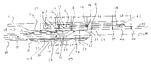
Figure 1 consists of a "Completion Fluid Logic Tool" (CLT, also referred to as
the
outer tool) 1 with a "Service Fluid Logic Tool" (SLT, also referred to as the
inner tool) 2
positioned in the inside bore 3 of the CLT 1. The SLT 2 and CLT 1 may take on
several
forms as described later in the description. A Piston 4 is located between an
inner housing
and outer housing 6 with ports 7 and 8 and 9 adjacent to the piston 4. Based
on the type
or form of the CLT, different porting arrangements may be used.
The objective of the porting arrangements, for example port 7 and port 8, is
to
allow tubing (internal) pressure 10 to act on each side of the piston 4, on
both sides of
seals 11 and 12, in order to keep the piston 4 in a pressure balanced, or near
pressure
balanced, condition so that any increase in tubing pressure 10, for any
reason, does not
cause the piston 4 to move. If the piston 4 does not move, the CLT 1 remains
in a dormant
state and does not function. The piston 4 may be shear pinned 13, or locked in
another
manner, until sufficient force, due to intentionally applied pressure 10 with
the SLT 2,
causes the piston 4 to shear or unlock.
Movement of the CLT 1 piston 4, via pressure 10 application from the SLT 2,
initiates activation of the CLT 1. The piston 4 may be mechanically attached,
via an
activation sleeve 14 for example, to a device to perform some downhole
function, such as,
opening and closing a sliding sleeve, initiating the setting of a packer,
initiating a
perforating gun, etc. Also, the piston 4 can be attached to a device
hydraulically,
electrically, magnetically, optically, pneumatically, etc., so when the piston
4 moves, the
CLT 1 is activated.
If a configuration utilizing the activation sleeve 14 is used, it may be
necessary to
have seals 15 and 16 that remains pressure balanced, or near pressure
balanced, through
ports 8 and 9. If it is necessary to keep the piston closely pressure
balanced, then the SLT
2 could have an additional port, not shown, to communicate with ports 8 and 9
simultaneously. It should also be apparent that the piston could have the
option of not
being pressure balanced in certain applications.
Figure 1 also shows the SLT 2 with an internal flow path 16 and an adjacent
flow
path 17. Pressure 10 or 18 can be applied to either of the flow paths 16 or
17. If pressure
is applied to flow path 16, then fluid would enter port 8 and pressure would
act below
CA 02717595 2010-10-13
12
the piston 4 biasing it upward and port 7 and flow path 17 would accept fluid
from above
the piston 4 to allow the piston to move upward. Furthermore, if pressure 18
is applied to
flow path 17, then fluid would enter port 7 and pressure 18 would act above
the piston 4
biasing it downward and port 8 and flow path 16 would accept fluid from below
the piston
4 to allow the piston to move downward. Therefore, the up and down movement of
piston
4 will cause the activation sleeve 14 to simultaneously move up or down to
function a
completion tool such as a sliding sleeve.
The longitudinal spacing, i.e. distances 19, 20, 21, 22, 23, 24, 25 but not
limited to
the number of distances, in conjunction with diametric changes i.e. recesses
26, 27, 28,
and 29 but not limited to the number of diameters, can be altered or adjusted
to achieve
different flow paths around the piston 4 or multiple pistons, through flow
paths 16, 17 or
other flow paths, to actuate one or more tools. Tools like packers or sliding
sleeves can be
actuated selectively if desired. A single flow path geometry can be used to
actuate all
tools. A flow path geometry can be selected so only one tool can be actuated
and any
others can not be actuated.
It should be understood that one SLT 2 can be built to activate all CLT 1
devices
located downhole, or one configuration SLT 2, say configuration geometry
"CS1", can be
built to only actuate a CLT 1 designed to match only a CLT with configuration
"CSI".
Almost unlimited combinations of fluid patterns, or codes, can be built by
varying the
distances or geometries mentioned above. This is analogous, to some extent, to
the
wireline shifting tool profiles where R, X, or XN profiles of shifting tools
only match R,
X, or XN profiles in nipples, respectively.
Figure 1 also shows seals arrangements on the SLT 2, i.e., seals 30, 31, and
32.
These seals form a full or partial seal in bore 3 on each side of flow paths
16 or 17 and on
each side of ports 7 and 8. These seals, or any combination of seals, can seal
around any
combination of flow paths or porting arrangements. Flow paths can be as simple
as one
port and one flow path or multiple flow paths and ports. The recesses can be
used to direct
flow around the tool as desired to achieve any flow logic desired.
Figure 1 shows three sets of Labyrinth seals 30, 31, 32 on the outside of the
SLT 2.
The Labyrinth type seal is a single groove or multiple grooves on the O.D. of
the SLT 2.
The O.D. 33 of the SLT 2 can simply be a close tolerance fit in bore 3 to
create a partial
seal or pressure drop in locations 34, 35, 36, and 37. The seal 33 can be of
any type
CA 02717595 2010-10-13
13
sufficient to allow a pressure buildup sufficient to move the piston 4 in the
CLT 1. In
others words, the seals 33 can leak and do not have to be perfect seals. If a
near-perfect or
perfect seal 33 is desired, other types of seals can be used such as elastomer
or elastomers,
plastics, non-elastomers, expandable such as in Figure 8, or retractable type
seals. Seals
could be o-rings, v-rings, Chevron stacks, bonded seals, molded seals, cup
type seals, etc.
It is preferable to use a seal, such as a Labyrinth seal 33 that has clearance
inside of the
CLT 1 and does not impart friction inside of the CLT 1 and does not tend to
stick inside of
the CLT 1 and the type that can seal multiple times without replacement. It is
also
desirable to have a seal, like a Labyrinth seal 33 that will tolerate various
types of particles
found down hole, i.e., sand, proppants, scale, etc. It is also desirable to
have a seal, like a
Labyrinth seal 33, which is not degradable by downhole temperature and various
chemicals.
Figure 1 shows the SLT 2 being conveyed into the well by work string 38. Let
it be
understood that the CLT 1 can be part of the casing string in the well or part
of a
completion or other tubular string in the well, as shown in Figure 7. An
objective is to
convey the SLT 2 to sufficient proximity of the CLT 1 to activate the CLT 1.
Conveyance methods can be by use of a workstring 38 which can be jointed pipe
or coiled tubing. Also the SLT 2 can be conveyed by electric line, wireline,
or a tractor, all
of which would need special pressure generating tools that can pump fluid to
the SLT 2.
Another option is to place a landing nipple above the CLT 1 and the SLT 2 can
be
attached to a wireline or coiled tubing conveyed lock or locator that
positions it in the
landing nipple. The positioning would be such that the SLT 2 and CLT 1 fluid
paths line
up. Once the fluid paths are lined up, pressure can be applied down tubing or
casing to
activate a CLT 1.
Figure 1 shows an orifice 39 and an orifice 40 located in housing 41. The
orifices
are downhole locating devices. If fluid is pumped through flow path 16 at a
given rate and
pressure through the SLT 2 and then moved through the orifice 39 or 40, the
orifice will
cause a pressure change, through 10 or 18, at the surface because the orifice
will allow
flow of fluid. When seals 33 of the SLT 2 enter the bore 42 of housing 41 the
flow rate out
of flow path 16 will be restricted. When seals 33 allow fluid communication
with the
orifice 40, or any combination of orifice, fluid flows through the orifice and
into annular
space 43. Distance spacing 23 can be adjusted to allow a fluid return path
through orifice
CA 02717595 2010-10-13
14
39 and into annular space 18. A surface operator can detect one or more
pressure changes,
based on the orifice geometric pattern, to tell him where the SLT 2 is
relative to the CLT
1. The pressure changes can be pre-calibrated at the surface so the operator
will know
what pressure change or sequence of pressure changes to expect for a
particular CLT 1.
Pressure changes or patterns can be created by changing orifice size, the
number of
orifices, replacing conventional orifices with a series of bores and recesses
( also referred
herein and in the claims as "orifices" or "orifice means") or any scheme that
will cause
pressure changes downhole.
Once the desired location, or CLT 1, is found, the SLT 2 can be moved up or
down
a given distance in order to position the SLT seals 33 around the CLT ports 7,
8, or 9. Of
course, tubing stretch or elongation due to pressure application must be taken
into
consideration at the anticipated applied pressure. If seals and port spacing
are long enough,
tubing movement is less of an issue. It should be noted that SLT 2 positioning
may not be
a critical issue, because in some cases, the SLT 2 can be slowly moved through
the CLT 1
while applying pressure to activate the CLT 1.
Also shown in Figure 1, is an optional pass-thru hole, or holes, 117. The flow
path
created by hole(s) 117 allows pressures near 18 and 118 to equalize in cases
where dead
space 118 exists below the SLT 2. The dead space may exist below SLT 2 when
there is
no fluid communication with the formation or in the well above the SLT 2. When
fluid is
pumped thru flow-path 10, fluid leakage may occur past seals 31 and 32. Fluid
leakage
past seal 32 must flow back up thru hole 117 when space 118 has no
communication with
its surroundings. Hole 117 allows pressure 18 and 35 to stay balanced, or near
balanced,
so an increase in pressure at either location 35 or 18, does not tend to force
the SLT 2 up
or down.
Figures 2 and 3 illustrate how an activation sleeve 14 of a CLT 44 is
activated by
the SLT 2 to open a sliding sleeve 45 to create a flow path 46 from the tubing
side 10 to
the annulus side 47. Applied pressure 16 builds pressure in chamber 52 to move
piston 4
upward into chamber 51 while fluid moves to low pressure side 17. The
hydraulic force on
piston 4 opens the sliding sleeve 45. The annulus side 47 can communicate with
an oil or
gas producing formation, or formations. This CLT 44 configuration can be used
to open or
close sliding sleeves located adjacent or in close proximity to in one or more
formations,
formations that are either isolated or non-isolated, for either injection into
a formation,
CA 02717595 2010-10-13
stimulating a formation, or producing from a formation. Once the sleeve 45 is
opened, the
SLT 2 can be positioned so that it can be used to fracture a selected zone as
shown with
flow path 46.
The casing 48 has holes or perforations 49 so that the flow 47 communicates
with
formation 50. An anchoring device can be attached close to the SLT to hold it
in position
while fracturing is taking place. The anchoring device for the SLT plays no
part of this
invention. Any one of a number of conventional means known to those skilled in
the art
may be utilized.
As shown in Figure 2, the sliding sleeve 45 may be closed when pressure
direction
is reversed in the SLT 2. Pressure is increased at port 17 which moves piston
4 down into
chamber 52 which closes the sliding sleeve 45.
Figure 4 illustrates the configuration of a CLT 53 that interfaces with a
packer 54
in order to set, or release, the packer 54. Pressure 17 is applied to stroke
piston 4
downward the compress and set the packer although pressure 10 could also be
used if the
SLT 2 were moved upward to change the porting arrangement. In this schematic
the
orifice locator has been moved to the top of the completion tool and CLT.
Orifice 55 and
57 are located in tubular housing 56. This drawing is for illustration only
since the
apparatus for setting the packer and the packer require more detail. It should
be noted that
packers require setting loads in the range of 50,000 pounds to fully set and
the SLT 2 has
hydraulic pressure capability to generate these forces when working on piston
4 areas. In
order to get additional force it is possible to attach two or more pistons
(similar to 4) and
simultaneously add more seals and ports to the SLT 2 geometry.
Figure 5 illustrates the configuration of a CLT 58. Fluid is pumped through
path 10
to move sleeve 60 that allows a flapper valve 59 to close when sleeve 60 moves
above the
flapper 61. Of course, the flapper valve design can be modified so that the
SLT (2) can
both open and close a flapper, or a ball valve, or any other type of valve.
The flow path
configuration between the CLT and SLT is such that a valve can be opened and
closed in a
single trip into the well. It is also possible to build one flow configuration
that opens a
valve and a second configuration that closes a valve.
Figure 6 illustrates a CLT 62 configuration for activating a Tubing Conveyed
or
Casing Conveyed perforating gun 63. The SLT 2 can be used in vertical or
horizontal
wells and can selectively detonate guns at any position in the well. In this
configuration,
CA 02717595 2010-10-13
16
the geometry around the piston changes. The piston 64 is no longer attached to
an
activation sleeve, but instead, has an added seal 65. Seals 65 and 66 prevent
pressure from
entering port 67 until the piston 64 moves up or down to uncover port 67. Once
port 67 is
uncovered, pressure 10 or 18 can be applied through the SLT 2, through port
67, and into a
timer or firing mechanism 68 to initiate firing of the perforating guns 63. Of
course firing
mechanism can be located anywhere in the perforating gun.
Figure 6 illustrates that the piston 4 (of Figure 1) or 64 can be in several
forms.
The piston, rather than communicating with a port 67, can act as a locking
mechanism, for
example. When the piston moves, it can cam out from under a collet, or set of
keys, or a
switch, or some other device that is directly or indirectly connected to an
activating device
which eventually activates some type of downhole tool, or CLT. Once again, the
option
exists to have no piston at all so the SLT communicates directly with some
type of device.
Also, it should be apparent that this piston arrangement is not limited to
perforating guns.
Also shown in Figure 6 is the orifice location finder 69 which is optional and
may be
located anywhere relative to the CLT 62.
Figure 7a, 7b, and 7c illustrates a possible completion hookup 70 inside of
casing
71 in formation 72. The hookup 70 consists of multiple CLT's 73,74,75,76, 77,
and 78 and
more than one zone of interest, zones 79 and 80. The hookup shows two zones of
tools
with each zone having a CLT actuated packer 81, sliding sleeve 82, and
perforating gun
83. A SLT 2 attached to workstring 38 can be moved from position to position
to activate
each CLT as desired. Those familiar with the state-of-the-art can readily see
that different
types of CLT's can be placed in any position and as many times as desired.
Figures 8a, 8b, and 8c show the SLT 84 positioned inside of a tubular 86 and
the
tubular has holes 87 which may be perforations that connect to a formation or
machined
holes that communicate with a CLT.
Figure 8A illustrates the SLT 84 with expandable labyrinth seals 85 rather
than
fixed O.D. labyrinth seals as seen in the SLT 2 (of Figure 1). The labyrinth
seals 85 are
one or more grooves placed on the O.D. of the expandable pads 88. Although,
the option
exists where the pads 88 have no labyrinth grooves. In this figure, the pads
88 are biased
outward by use of springs 89 under the pads to force contact, or near contact,
with the I.D.
of the tubular 86. The pads 88 approach or achieve a 360 degree contact around
the I.D. of
the tubular 86. Figure 8B shows grooves 95 between two or more sections of
pads 96 and
CA 02717595 2010-10-13
17
97. The pads 96 and 97 are blocked by off-sets 93 and 94 built into the sides
of the pads
96 and 97. The off-sets 93 and 94 restrict fluid movement between the pads 96
and 97
when the pads are expanded to meet the I.D. of the tubular 86. Each section of
pad has a
set of off-sets. The pads 88 are retained to the SLT 84 by lips 90 on the pad
88 protruding
under mating lips 91 on housing 92. The components of the pads and the body of
the SLT
84 restrict fluid flow past the pads thereby directing fluid through flow path
16 and into
CLT holes or perforations 87 in the tubular 86.
Figure 8B illustrates the SLT 84 in a similar manner as figure 8A except the
pads
88 are biased outward hydraulically with pressure from hole 16 through ports
98 and into
chamber 99 located under each set of expandable pads 96 and 97.
Figure 8C illustrates the SLT 84 with the pads 96 and 97 fully expanded
against
the I.D. 100 of the tubular 86 due to spring loading under the pads. The
hydraulic version
would be similarly expanded since pressure at 98 is higher than pressure at
101. In either
case, the expanded pads direct fluid, or slurry, into and through the tubular
holes 87.
Figure 9 illustrates a downhole tool hookup for perforating one or more zones
with
a Tubing Conveyed Perforating Gun (TCP). One or more CLT's, 102 and 103 are
positioned above one or more TCP guns 111 and 112. When the SLT 2 is
positioned inside
the CLT 102, pressure at 16 works on piston 104 and shears screw 106, or
locking device,
to allow fluid from 16 to communicate with control line 107. Control line 107
either
hydraulically, electrically, optically, etc. communicates with firing head 110
and triggers
firing head 110 to detonate TCP gun 112. It may be desirable to detonate the
lowermost
guns 112 first to assure that the control line 107 is not damaged by
detonation of guns 111.
If a control line 107 is damaged, it is possible to shift or bias piston 104
back to the closed
position to shut off fluid communication through the control line 107, if the
control is
hydraulic. Shear screws 106, or locks, are of sufficient strength to prevent a
piston 104,
from another CLT 103, from moving due to TCP shock loads from TCP gun
detonation
112. After TCP gun 112 is detonated the SLT2 may be moved to CLT 103. Pressure
applied from 16 moves piston 105 so that communication is achieved through
control line
108 which activates firing head 109 and detonates TCP gun 111. Multiple CLT's
can
communicate with multiple TCP guns in any manner, i.e., CLT 102 can only fire
gun 111,
CLT 102 can only fire gun 112, CLT 102 can simultaneously fire both guns 111
and 112,
CLT 103 can do the same as CLT 102, or both CLT 102 and CLT 103 can both fire
a gun
CA 02717595 2010-10-13
18
or guns to provide a means to have a backup firing method. Firing of the guns
111 and 112
will perforate casing 113 and communicate with formations 114 and 115.
Therefore, any
combination of CLT's and guns can be used to fire guns selectively,
simultaneously, or
provide redundancy in the firing system. Also, the SLT 2 may be moved from the
bottom
up or the top down to fire guns in any sequence.
Also shown in Figure 6 is the orifice location finder 69 which is optional and
may
be located anywhere relative to the CLT 62.
The TCP guns 111 and 112, or more, can be spaced out through multiple zones
114
and 115, or more, to selectively perforate zones without the need to move the
workstring
116. Also the workstring 38 can be moved to reposition guns relative to each
zone before
detonation without pulling the SLT 2 out of the well by use of jointed pipe at
the surface.
A dual string handling system can be used on the rig to move the tubing
conveyed
guns up the hole along with the SLT work string 38 as joints are removed from
workstring
116.
DESCRIPTION OF OPERATION
A single or series of Completion Logic Tools (CLT's), aka the completion, may
be
positioned in well casing, as in figure 7a, 7b, or 7 c, or in open hole, or
may be cemented
in open hole. The objective is to activate any type of CLT, examples are shown
in figures
2, 3, 4, 5, 6, 7, 8 or 9, by conveying into the well a service Fluid Logic
Tool (SLT) by
anyone of the above mentioned conveying methods or by running the SLT in place
with
some other part of the completion and making a connection at a later time. A
particular
SLT may be run that only activates a particular type of CLT or series of
CLT's. A
particular SLT may be run to activate all CLT's.
A typical operational sequence may be conveying the SLT to the bottom of the
completion. Once the SLT is below the lowermost CLT, fluid is circulated down
the
workstring and into the SLT flow path 10, see figure 1. Flow rate and pressure
are
maintained while moving the workstring upward to activate the first CLT. As an
option,
when the SLT enters a restriction 42 between orifice 39 and 40, see Figure 1,
a pressure
change and flow rate change will occur signaling the operator of the position
of the SLT
relative to the inside of the CLT. The presence of the orifice 39 or 40 will
provide
CA 02717595 2010-10-13
19
increased flow, at a rate predetermined by surface tests. Also, the
longitudinal spacing
between orifice and number of orifice will provide a "finger print" that
identifies the CLT
to be activated. Once it is verified that the SLT is in the proper CLT, the
SLT is moved
slowly upward until the porting arrangements between the CLT and SLT
sufficiently
match to create a flow path to the piston 4, figure 1, of the CLT.
As shown in Figure 1, the fluid will enter port 8, act on the piston 4, shear
and
move the piston while fluid above the piston exits port 7 allowing the piston
to move and
begin the actuation process of the CLT. Of course the flow path can be
reversed to enter
flow Path 7 and exit port 8 to move the piston back the other direction if it
maybe desired
to de-activate or re-cock a CLT. The pressure required to move the piston will
vary
depending on the piston area, frictional forces, shear screw value, etc. The
piston can be
designed to completely move across port 7 to create a flow path from port 8 to
7 to
achieve return fluid up through flow path 17 so that returns can be sensed at
the surface.
The return fluid can act as a tell-tale that the piston has shifted.
It should be understood that application of surface pressure into the
workstring
may cause the workstring to elongate therefore longitudinal spacing of the
ports may have
to be lengthened, or adjusted, to compensate for tubing movement. Or it may be
necessary
move the workstring up or down to compensate for tubing movement due to an
increase in
pressure inside the workstring.
Another operational sequence may be to "sweep" the SLT upward through the
CLT or CLT's. In this case, the workstring is slowly moved upward while
pumping down
the workstring at a constant pressure and flow rate. Pressure is maintained
high enough to
shift the pistons and activate the CLT's. The spacing of the ports is such
that pressure is
applied long enough to the CLT's to fully activate the CLT's while the
workstring
continues its motion upward.
Movement of the SLT can be either up or down, if desired.
Figures 7a, 7b, and 7c show a typical completion in a zone with a packer, a
sliding
sleeve, and a perforating gun. An operational sequence may be to move the SLT
to set the
CLT packer, then open the CLT sliding sleeve, then detonate the CLT
perforating gun,
then move the SLT to straddle the sliding sleeve, then pump a frac job into
the formation,
next reverse out, and last, close the sliding sleeve. In this case, not shown,
a sand control
screen can be positioned in close proximity to the perforating guns. The sand
control
CA 02717595 2010-10-13
screen may be shut off with sliding sleeves to prevent production flow and
reopened at a
later time.
To better understand the operation of the SLT in a CLT it is beneficial to
explain
how to achieve pressure and flow rate necessary to activate a CLT. Fluid can
be pumped
down the workstring in terms of gallons per minute (GPM). The GPM is based on
the
typical size of fluid pumps on rigs. Typically most rigs have 5 BPM mud pumps
so the
objective is to generate at least 3000 PSI at the CLT using a mud pump.
Typically packers
are set or activated with pressures in the range from 2500 PSI to 4000 PSI.
About 3000
PSI can be achieved with 105 gal/min. With 42 gallons in a barrel, a pump rate
of 2.5
BPM is needed to achieve 3000 PSI. Further testing should show that pump rates
higher
than 2.5 BPM will generate pressures up to 4000 PSI with '/4" diameter
orifice. This is
static pressure at the tool even though fluid is leaking around the O.D. of
the SLT. In some
cases, it may be necessary to calculate surface applied pressure in
combination with well
hydrostatic pressures to determine actual pressure at the tool. For salt
water, the weight of
the fluid is .5 PSI/foot, so in a 10,000 foot well hydrostatic pressure could
be 5,000 PSI.
Depending on the fluid position in the tubing and annulus, hydrostatic
pressure may have
to be added or subtracted from the surface applied pressure to get actual
pressure at the
CLT.
Orifice size communicating with the Piston in the CLT needs to be of
sufficient
size to supply fluid volume necessary to move the piston up or down. The
smaller the
orifice, the longer it will take the piston to move due to volume
displacement. A 1/4" size
orifice was used in a test because that is a typical size of orifice used in
hydraulic set
packers when the packers are set by application of tubing pressure. Flow rate
formulae,
such as Flow Rate = Orifice Area x Velocity, and other formulae, can be used
to calculate
the flow rate required to make a piston move within a specified time range.
Of course the piston moves when pressure is applied to a specific area on the
piston, and the piston can be shear-pinned to shear at a specified pressure.
This is
important if the SLT is sweeping through the CLT. Seal spacing is lengthened
or
shortened based on the speed the SLT is moving through the CLT and also based
on
tubing stretch calculations.
Seal spacing may be increased to compensate for tubing elongation when
pressure
is applied to the tubing. A simple formulae AP=12EtiL/[RL(.5-v)], from
"Roark's
CA 02717595 2010-10-13
21
Formulas For Stress and Strain", seventh addition, is used to calculate the
workstring
movement with applied surface pressure.
If the SLT is run un-anchored, i.e., tubing movement can occur, then the seal
spacing on each side of the port in the SLT may be increased and the bore
length on each
side of the receiving port in the CLT may be increased, to assure that the SLT
properly
communicates with the CLT. If the SLT has an anchoring device on the
workstring, then
the seal and bore spacing can be reduced since very little tubing movement
will occur at
the SLT when pressure is applied.
Referring to Figure 1, if pumping down the workstring, it would be desired
that the
input flow area at point 16 must always be greater than the flow area at
orifice 8 + the
annular flow area around the SLT and inside the CLT at seal 31, if seal point
31 is a
leaking type seal. If multiple seal location are leaking type seals, i.e.,
seals 30, 31, and 32,
then these flow areas plus the orifice flow areas must be greater than the
input flow area at
point 28. If pumping down the annulus at point 18, then input flow area thru
port 17 must
be greater than the orifice 7 flow area + the annular flow area past any seals
or restrictions
around the SLT.
In summary, in order to build pressure on the piston 4, the input flow areas
must
provide enough flow to achieve an adequate pressure increase at the piston, or
activating
device, in order to activate a CLT. For example, if the piston 4, or
activating device,
requires 3,000 PSI to begin the activation process of a CLT, then input flow
area must be
great enough to achieve this pressure increase while also giving up fluid at
any leak path
locations around the SLT. Of course, if the seals 30, 31, and 32 are non-
leaking type seals
then the fluid input requirements at point 16 may be reduced in order to
activate a CLT
device.
The above formulae may be expanded if additional orifice means at point 8 are
present. For example, if there are three pistons programmed into the fluid
path geometry,
each having an orifice arrangement on each side of the pistons. Each piston
actuates a
different downhole device at a single position of the SLT. The input flow area
at 28, must
then be great enough to supply multiple orifice and multiple leaking seal
paths.
The above also applies to the position finding orifice 39 and 40. The input
flow
area at location 28 needs to be of sufficient size to achieve a pressure
change at the surface
when the SLT passes through bore 42 and crosses orifice 39 or 40.
CA 02717595 2010-10-13
22
Furthermore, the flow area through balance port 117, should be of sufficient
size to
balance pressure above and below the SLT, if the SLT is not anchored in
position. Ideally
flow area 117 should be greater than input flow area 28, but may not be
absolutely
necessary.
The above discussion primarily relates to activating a CLT with a SLT.
Referring
to Figure 3, where the SLT moves to a gravel packing, acidizing, or frac
position, in this
case inside of a sliding sleeve 45 (Figure 2), flow area 10 must be of
sufficient size to
handle to require fluid volume to achieve stimulation of the well formation.
For example,
the flow area I.D. at 10 may have to have a 1.5" I.D. to allow a pump rate of
15 BPM
through the tool and into the formation 50. Of course, the flow area can be
adjusted to the
size needed to achieve the required flow rate based on the available room
inside of the
CLT. It should also be understood that a SLT can be custom designed to apply
pressure to
the inside of any type of completion tool other than a CLT, if the completion
tool
geometry can be matched between the SLT and the completion tool.
For those who understand the art of completing wells, it should be apparent
that
many combinations of CLT's can be created and that the SLT has great
flexibility to
operate in deferent types of hookups or completions.
The invention being thus described, it will be obvious that the same may be
varied
in many ways. Such variations are not to be regarded as a departure from the
spirit and
scope of the invention, and all such are intended to be included within the
scope of the
non-limiting claims.