Note: Descriptions are shown in the official language in which they were submitted.
CA 02717830 2015-04-29
79291-130
1
DESCRIPTION
METHOD FOR REPAIRING A GAS TURBINE COMPONENT
BACKGROUND OF THE INVENTION
The present invention relates to the technology of gas turbines. It refers to
a
method for repairing a gas turbine component.
PRIOR ART
Today, gas turbines have turbine inlet temperatures of more than 1400 C.
Accordingly, the components of those gas turbines such as blades, vanes or
liners
are exposed to a high thermal load and mechanical stress. As those components
are usually made of expensive high-temperature resistant materials, it is
desirable
to repair those components, when damaged, instead of replacing them. However,
the repair of damaged gas turbine components is of limited quality, when the
damaged section is removed and an insert is manufactured to fit into the
removed
region, as the insert has to be manufactured with high precision to avoid a
loss in
mechanical stability and change in the flow characteristics of the machine.
Document EP 1 620 225 B1 discloses a method for repairing and/or modifying
components of a gas turbine. Initially, at least one particularly damaged
section of
the component, which is to be repaired is extracted from the component. A CAD
model is then produced for the replacement part by building the difference
between nominal parametric CAD model and measured geometry data set of the
damaged component. The replacement part is subsequently produced with the aid
CA 02717830 2010-10-15
2
of an additive manufacturing process. Finally, the produced replacement part
is
integrated into the component, which is to be repaired.
Document US 6,355,086 B2 discloses a method and apparatus for fabricating a
component by a direct laser process. One example of such a component is a gas
turbine engine blade having an abrasive tip formed directly thereon.
Document WO 2008/046386 A1 teaches a method for producing a gas turbine
component with at least one closed outer wall and an inner structure bounded
by
the or each closed outer wall and defining hollow spaces, comprising the
following
steps: a) providing a three-dimensional CAD model of the gas turbine component
to be produced; b) breaking down the three-dimensional CAD model into
horizontal, substantially two-dimensional layers; c) building up layer by
layer the
gas turbine component to be produced with the aid of a additive manufacturing
process using the layers generated from the CAD model in such a way that the
or
each outer wall is built up together with the inner structure and is
accordingly
connected to the inner structure with a material bond.
The document EP 1 231 010 A1 discloses a method of repairing gas turbine
engine components. The method includes removing the damaged portion and
fabricating an insert to match the removed portion. The insert is precision
machined and crystallographically matched to the original component, and then
bonded to this component using transient liquid phase bonding techniques and
suitable heat treatment. Although the document contains a wealth of
information
on the bonding process, no details of the precision machining of the insert
are
given.
Document US 5,269,057 teaches a method for replacing airfoil components
includes the steps of identifying a portion of the airfoil to be replaced,
removing the
portion by a nonconventional machining process, such as continuous wire
electrical discharge machining, and forming a replacement member utilizing a
CA 02717830 2015-04-29
79291-130
3
similar cutting process. A cutting path utilized to remove the portion to be
replaced
and to form the replacement member includes interlocking projections and
sockets
and may include one or more tapers along the cutting path so that the portion
may be
removed only by lifting in one direction. For the cutting, an electrical
discharge cutting
wire moves along the outside of a CNC programmed cutting path.
All the known methods for repairing gas turbine components are costly, have a
low
flexibility and productivity, and are difficult to put into practice.
Furthermore, bad
tolerances lead to a bad quality, the dependence on a 3D model makes the
repair
expensive and elaborate, and these methods are limited to the repair of
components
with damages of low degradation and distortion.
SUMMARY OF THE INVENTION
According to an aspect of the present invention, there is provided a method
for
repairing an ex-service gas turbine component comprising the steps of:
removing a
damaged section from said gas turbine component, the damaged section being
removed in form of a cut-out section along a split line as one single cut-out
piece;
measuring the cut-out piece to obtain an actual non-parametric geometry data
set of
the cut-out piece; adding an additional material surcharge around at least
part of the
split line to the geometry data set of the cut-out piece to allow for a
compensation of
the material loss due to one or more of cutting, the preparation of a split
line surface
and a final or individual adaptation of a standard 3-D article geometry to the
individual
ex-service gas turbine component to be repaired; manufacturing a 3-D article,
which
fits in said gas turbine component to replace the removed damaged section,
based
on said geometry data set of the cut-out piece, and joining said gas turbine
component and said 3-D article inserted therein.
Some embodiments may provide an improved method for repairing a partly damaged
gas turbine component, which does not require a parametric CAD model of the
cut-
out piece of the component, which can be applied with reduced cost, resulting
in
improved flexibility and productivity, and has the advantage of high quality.
CA 02717830 2015-04-29
79291-130
3a
In one aspect of the method, the damaged section is removed in form of a cut-
out
section along a split line as one single cut-out piece, the cut-out piece is
measured to
obtain the actual non-parametric geometry data set of the cut-out piece, and
the 3-D
article is manufactured based on the geometry data set of the cut-out piece.
Throughout the following description, a "geometry data set" is meant to be a
set of
measured points representing a physical part; a "CAD model" is meant to be a,
by
means of a computer software created, virtual representation of a physical
part,
CA 02717830 2015-04-29
79291-130
4
whereby in a "parametric" CAD model the geometry of the virtual representation
is
described by mathematical functions (e.g. NURBS), and in a "non-parametric"
CAD model the geometry of the virtual representation is described by
primitives
such as points, triangles, rectangles, etc..
According to one embodiment of the inventive method a virtual 3-D article in
form
of a CAD model is created from said measured geometry data.
According to another embodiment of the invention damaged or missing areas of
the cut-out piece are virtually rebuilt to create and/or modify and/or extend
said
CAD model.
According to another embodiment of the invention the CAD model includes
information about the inner surface, potential distortions, local wall
thickness
modifications and positions of cooling air holes of the ex-service gas turbine
component.
According to another embodiment of the invention an additional material
surcharge
is added around at least part of the split line to the geometry data set of
the cut-out
piece to allow for a compensation of the material loss due to cutting and/or
the
preparation of a split line surface and/or a final or individual adaptation of
a
standard 3-D article geometry to the individual ex-service gas turbine
component
to be repaired.
According to another embodiment of the invention the 3-D article is
manufactured by an
additive manufacturing technology such as selective laser melting (SLM),
selective laser
sintering (SLS) or electron beam melting (EBM).
A method for making metallic or non-metallic products by a free-form laser
sintering from
a powder material is for example known from document DE 102 19 983 B4. Another
method for manufacturing a moulded body, particularly a prototype of a product
or
component part, a tool prototype or spare part, in accordance with three-
dimensional CAD
CA 02717830 2015-04-29
79291-130
data of a model of a moulded body, by depositing layers of a metallic material
in powder
form, is disclosed in document EP 946 325 B1. Furthermore, document US
6,811,744 B2 teaches device and arrangement for producing a three-dimensional
object by means of a ray gun for controlled fusion of a thin layer of powder
on the
5 worktable.
According to another embodiment of the invention the 3-D article is
manufactured
by investment casting or milling.
According to a further embodiment of the invention before joining the
manufactured 3-D article into the ex-service gas turbine component, the
manufactured 3-D article is recontoured into a recontoured 3-D article to
reach
optimum conditions of the split line surface and/or gap width for the final
joining
process.
In some embodiments, the recontouring is done by removal of a fixed thickness
of material.
As an alternative the recontouring may be done by individual adaptive
machining.
According to another embodiment of the invention the adaptive machining is
based on the individually scanned ex-service gas turbine component, which is
compared with the 3-D article geometry.
Alternatively, the adaptive machining may use a geometry data set based on the
evaluation of a limited number of scanned gas turbine components of the same
kind.
According to another embodiment of the invention the recontouring process is
done by a subtractive machining process, such as milling, grinding or electro
chemical machining (ECM).
CA 02717830 2015-04-29
79291 -1 30
6
According to just another embodiment of the invention, further to the
recontouring,
other pre-joining processes are applied to the 3-D article to make the 3-D
article
ready for insertion.
In some embodiments, preferably, the pre-joining processes include a heat
treatment
and/or chemical cleaning of the surfaces.
According to another embodiment of the invention the joining of said gas
turbine
component and said 3-D article is done by brazing or welding or a combination
thereof.
BRIEF DESCRIPTION OF THE DRAWINGS
Non-limiting examples of embodiments of the present invention are now to be
explained more closely by means of different embodiments and with reference to
the
attached drawings.
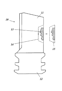
Fig. 1 shows, in a side view, a damaged gas turbine component in form
of a
blade, which may be a starting point of the method according to an
embodiment of the invention;
Fig. 2 shows the blade of Fig.1 and the split line around the damaged
region,
where a single piece of a blade will be cut-out;
Fig. 3 shows an arrangement for measuring the geometry of the cut-out
piece
of Fig. 2;
Fig. 4 is a representation of the CAD model of the 3-D article to be
manufactured for replacing the cut-out piece;
Fig. 5 shows the principles of the recontouring process of the
manufactured 3-
D article, whereby additional information from the gas turbine
component itself may be used;
CA 02717830 2015-04-29
79291-130
7
Fig. 6 shows how the manufactured and recontoured 3-D article is
inserted
into the gas turbine component to be repaired;
Fig. 7 shows the post machining process after the 3-D article into
component
have been joined; and
Fig. 8 shows in a process scheme various alternative routes of processing
within the method of an embodiment of the invention.
DETAILED DESCRIPTION OF DIFFERENT EMBODIMENTS OF THE INVENTION
In general, an embodiment of the present invention comprises a method for
repairing
an ex-service gas turbine component by removing a damaged location, which
method
allows a right gap control, followed by replacing the respective location by a
precisely
fitting 3-D article. This 3-D article can be manufactured by additive
manufacturing
processes, such as selective laser melting (SLM), selective laser sintering
(SLS),
electron beam melting (EBM) or by standard methods, such as investment casting
or
machining process such as milling.
The method starts with the damaged gas turbine component an example of which
is
shown in Fig. 1. The gas turbine component 10 in this figure has the form of a
turbine
blade with an airfoil 11 and a root 12. This gas turbine component 10 is
damaged as
it shows a damaged area 13 at one of the edges of the airfoil 11.
CA 02717830 2015-04-29
79291-130
8
As shown in Fig. 2 the heavily damaged section or area 13 on the ex-service
gas
turbine component 10 is removed using a machining process, where the cut-out
section will be available as one, single cut-out piece 15. Therefore,
machining
processes, such as electrical discharge machining (EDM), water jet, laser or
plasma cutting are preferentially applied. With such machining processes the
loss
of material in the split line 14 between the cut-out piece 15 and the gas
turbine
component 10 can be reduced to a minimum. A milling or grinding process cannot
be used, as no cut-out piece would be available. The machining process has
preferably a marginal influence on the cutting area (no oxidation, small heat
affected zone and low roughness).
After the machining process the cut-out piece 15 including the damaged section
(outer and inner contour) is measured using tactile or optical methods in
order to
obtain the actual, non-parametric geometry data set of this piece. Fig. 3
shows the
respective optical or tactile measuring system 16, wherein an optical scanning
head 17 and/or tactile scanning head 18, which are controlled in their
movement
by a control 19, are used to pickup the non-parametric geometry data set of
the
cut-out piece 15.
Next, the damaged/missing areas are virtually re-built and potentially
modified
(e.g. by Reverse Engineering) allowing to create and/or modify and/or extend a
final CAD model of the cut-out piece 15, also called 3D article 20 (Fig. 4).
The
resulting CAD model of this 3D article 20 includes the information about the
inner
surface, potential distortions, local wall thickness modifications and
position of
cooling air holes of the ex-service component. An additional material
surcharge 21
is added around at least part of the split line to the geometry data set of
the cut-out
piece 15. This allows a compensation of the material loss due to cutting,
preparation of split line surface and, if needed, also a final or individual
adaptation
of a standard 3D article geometry to the individual ex-service gas turbine
component 10 to be repaired.
CA 02717830 2010-10-15
9
Based on the CAD model of the 3-D article 20 the reconditioning procedure
continuous with the manufacturing of a real 3-D article (22 in Fig. 5) For the
related
subsequent reconditioning chain three different approaches are generally
possible:
- The first variant generally allows the manufacturing of the 3-D
article 22 in
form of a component of standard size without any additional information or
measurement of the individual ex-service gas turbine component 10 to be
repaired. There is a standard material surcharge on the standard cut-out
piece for compensation of the cutting process and for surface preparation
for joining. Accordingly, no 3-D model or measurement of the gas turbine
component 10 is used. The fixed thickness of material is removed during
recontouring (see upper half of Fig. 5, where a machining system 23 with a
machining tool 24 into respective control 25 are used for recontouring).
- The second option would include a post machining (adaptive
machining) of
a standardized replacement article or "coupon" based on the individually
scanned ex-service gas turbine component with aperture (see lower half of
Fig. 5), which is compared with the 3-D article geometry. In this case the
gas turbine component or blade 10 to be repaired has to be individually
scanned, or alternatively, a geometry data set based on the evaluation of a
limited number of scanned blades is used.
- The third alternative would ask for an individual scanning of each gas
turbine component or blade 10 to be repaired after removal of the damaged
area in order to generate individual machine data sets for the additive
manufacturing of respective 3-D articles.
The selection of the best suited variant strongly depends on the degree of
deformation to be expected on the individual parts of a set of blades to be
repaired. Fig. 8 shows in a process scheme various alternative routes of
processing within the method of the invention. The scheme begins with the
start S
that is the measurement of the cut-out piece 15.
CA 02717830 2010-10-15
Variant A is favoured, when the gas turbine component 10 to be repaired has
only
low distortion and damages. In this case, a standard material surcharge on the
standard cut-out piece is provided for compensation of cutting process and for
surface preparation for joining. No 3-D model or measurement of the gas
turbine
5 component are necessary; a layer of fixed thickness is removed (A1).
Variant B is favoured, when the gas turbine component 10 to be repaired has
medium distortion and damages. In this case, a standard material surcharge on
the cut-out piece is provided plus additional oversize for adaptive machining
and
10 for surface preparation for joining. When the joining process requires
only a
medium/low gap precision, a statistical evaluation of damages of components is
used for the generation of a model and material removal with fixed thickness
(61).
When the joining process requires a high gap precision, each component is
measured and adaptive machining is applied (62).
Variant C is favoured, when the gas turbine component 10 has a high distortion
and worn out locations. In this case, there is an individual manufacturing of
the
inserts with a material surcharge on the cut-out piece for compensation of the
cutting process and for the surface preparation for joining. When the joining
process requires only a low gap precision, either no 3-D model or measurement
of
the gas turbine component are necessary and a layer of fixed thickness is
removed (C1), or a statistical evaluation of damages of components is used for
the
generation of a model and material removal with fixed thickness (C2). When the
joining process requires a high gap precision, each component is measured and
adaptive machining is applied (C3).
Based on the generated geometry data set of the cut-out piece, the 3D article
22
can be manufactured by an additive manufacturing technology, such as selective
laser melting (SLM), selective laser sintering (SLS) or electron beam melting
(EBM). Also conventional methods, such as investment casting or milling can be
used. The decision of the manufacturing technology also depends on the degree
CA 02717830 2015-04-29
79291-130
11
of deformation to be expected on the individual parts of a set of blades to be
repaired.
Before joining the manufactured 3-D article 22 into the ex-service gas turbine
component 10,
each 3-D article 22 needs to be recontoured to reach optimum conditions of the
split line
surface (e.g. roughness, gap geometry/tolerance) for the final joining
process. Depending on
the selected approach, the recontouring step can be done by removal of a fixed
value
(thickness) or by individual adaptive machining. For the recontouring a
standard process is
used, such as milling, grinding or electro chemical machining (ECM); Fig. 5
shows an
exemplary machining system 23 for recontouring the manufactured 3-D article 22
into a
recontoured 3-D article 22', with a rotating machining tool 24 and a
respective control 25.
Besides the recontouring, other pre-joining processes (and chemical cleaning
of the surfaces
to be joined) may be needed depending on the manufacturing process, e.g. pre-
heat
treatments for improved weldability, stress relief heat treatments for 3D
articles made by
additive manufacturing technologies, etc..
The joining of the manufactured 30 article into the ex-service gas turbine
component 10 can
be realized with a standard and specifically adapted joining process, such as
brazing or
welding or a combination thereof. A final heat treatment and post machining
(see Fig. 7) is
carried out at the end of the reconditioning chain.
Some embodiments may include advantages over the known technologies from among
the
following:
- No measurement of the whole component to get the information about
the ex-service influence such as distortion, depending on approach.
- No CAD model of the whole component is required.
- No parametric CAD model of the 3D article (cut-out piece) is required.
- Characteristic issues/information of the cut-out piece due to service and
new manufacturing are covered with the scan of the cut-out piece.
CA 02717830 2010-10-15
12
- Cost and scrap rate reduction.
- Flexibility and productivity are improved.
- Extended repair to highly loaded areas.
LIST OF REFERENCE NUMERALS
gas turbine component (e.g. turbine blade)
11 airfoil
12 root
10 13 damaged section
14 split line
cut-out piece
16 measuring system (optical or tactile)
17 optical scanning head
15 18 tactile scanning head
19 control
3-D article (data set)
21 material surcharge
22 3-0 article (manufactured)
20 22' 3-D article (recontoured)
23 machining system
24 machining tool
control
start
25 A,B,C repair process requirement
A1,61,62 repair process requirement
C1,C2,C3 repair process requirement