Note: Descriptions are shown in the official language in which they were submitted.
CA 02718416 2016-02-19
MULTI-FUNCTION, FOOT-ACTIVATED CONTROLLER FOR IMAGING SYSTEM
FIELD OF THE INVENTION
The present invention generally relates to the field of imaging systems that
utilize imaging equipment and
a movable table and, more particularly, to foot-activated controllers for such
imaging systems.
BACKGROUND
Medical imaging systems exist that utilize an adjustable patient table and
appropriate imaging equipment
One such imaging system is commonly referred to as a 'urology table. Urology
tables are used to perform
various urology procedures. It is common for these types of medical imaging
systems to utilize foot-activated
controllers for communicating with the movable patient table and the imaging
equipment. One foot-activated
controller is typically provided for communicating with the movable patient
table, while a separate foot-activated
controller is typically provided for communicating with the imaging equipment.
Known foot-activated controllers for the patient table incorporate a number of
pedals or switches for
controlling the position of the patient table, Patient tables for urology
applications typically are movable in each of
a vertical dimension, as well as longitudinal and lateral dimensions within a
reference plane that at least generally
coincides with a supporting surface of the patient table. These tables may
also be tilted about a horizontal axis
(e.g., to raise the patients head and simultaneously lower the patients feet;
to lower the patients head and
simultaneously raise the patient's feet). Known foot-activated controllers for
the imaging equipment incorporate a
number of pedals or switches for controlling various aspects of the image
acquisition function.
SUMMARY
A first aspect of the present invention is embodied by an imaging system.
Components of this imaging
system Include an imaging assembly, a table, a table positioner, and a foot-
activated controller. The table
positioner may Interact with the table, while the foot-activated controller is
operatively interconnected with each of
the Imaging assembly and the table positioner. The foot-activated controller
includes at least one actuator,
including at least one first actuator and at least one second actuator. Each
first actuator is dedicated to
communicating with the imaging assembly. Each second actuator is dedicated to
communicating with the table
positioner.
A second aspect of the present invention is embodied by an imaging system.
Components of this
imaging system include an imaging assembly, a table, a table positioner, and a
foot-activated controller. The table
positioner may interact with the table, while the foot-activated controller is
operatively interconnected with each of
CA 02718416 2010-09-13
WO 2009/114365
PCT/US2009/036094
the imaging assembly and the table positioner. The foot-activated controller
includes first and second controller
sections that may be selectively joined and separated. Each of the first and
second controller sections includes at
least one actuator, and each such actuator communicates with at least one of
the imaging assembly and the table
positioner.
Various refinements exist of the features noted in relation to the second
aspect of the present invention.
Further features may also be incorporated in the second aspect of the present
invention as well. These
refinements and additional features may exist individually or in any
combination. The foot-activated controller may
include at least one first actuator and at least one second actuator. Each
first actuator may be dedicated to
communicating with the imaging assembly (e.g., one or more components that are
directed to the acquisition of an
image). Each second actuator may be dedicated to communicating with the table
positioner.
Various refinements exist of the features noted in relation to each of the
above-noted first and second
aspects of the present invention. Further features may also be incorporated in
each of the above-noted first and
second aspects of the present invention as well. These refinements and
additional features may exist individually
or in any combination in relation to each of the first and second aspects.
That is, each of the following features
that will be discussed is not required to be used with any other feature or
combination of features unless otherwise
specified.
The imaging system may be utilized for any appropriate application. In one
embodiment, the imaging
system is used for a medical application (e.g., for performing one or more
urology procedures), and thereby may
be referred to as a medical imaging system. Any appropriate imaging equipment
may be utilized by the imaging
system, including without limitation one or more components for providing an
imaging functionality such as x-ray,
tomography, fluoroscopy, store last image hold, magnification, and any
combination thereof.
The table may be movable in any appropriate manner and/or in any appropriate
dimension or combination
of dimensions. The table may be moved in each of first and second directions
within a reference plane that at
least generally coincides with a supporting surface of the table. These two
different directions may be orthogonal
to each other for instance one defining a longitudinal dimension or
longitudinal axis (e.g., coinciding with a height
dimension of a patient lying on the table, or coinciding with a dimension in
which the patient's head and feet are
spaced when lying on the table) and the other defining a lateral dimension or
axis (e.g., coinciding with a
dimension in which a patient's shoulders would be spaced if the patient were
to lie on his/her back on the table in
the above-noted manner). The longitudinal dimension or axis may coincide with
the long axis of the supporting
surface of the table, while the lateral dimension or axis may coincide with
the short axis of the supporting surface
of the table.
Another motion that the table may undergo is in the vertical dimension ¨ a
motion that changes the
elevation of the table (and including the entirety of its supporting surface).
Yet another type of motion that may be
utilized for the table is a movement at least generally about a first axis.
This first axis is subject to a number of
characterizations, which apply individually and in any appropriate
combination. For instance, the first axis may be
horizontally disposed, may extend in the lateral dimension, or both. In one
embodiment, the lateral dimension of
the supporting surface of the table is maintained parallel to horizontal.
Movement of the table at least generally
2
CA 02718416 2010-09-13
WO 2009/114365
PCT/US2009/036094
about the first axis may be characterized as a tilting of the table. The angle
at which the table is disposed relative
to horizontal (e.g., the angle between the longitudinal axis of the table and
horizontal) may be referred to as a "tilt
angle." Tilting of the table may be undertaken to raise the patient's head and
simultaneously lower the patient's
feet, may be undertaken to lower the patient's head and simultaneously raise
the patients feet, or both.
At least four first actuators may be utilized by the foot-activated
controller. One first actuator may be
utilized to control x-ray imaging (e.g., dedicated to controlling the
acquisition of an x-ray image, for instance by
turning on/off x-ray equipment); one first actuator may be utilized to control
fluoroscopy imaging (e.g., dedicated to
controlling the acquisition of a fluoroscopy image, for instance by turning
on/off fluoroscopy equipment); one first
actuator may be used to establish/select the magnification mode of an image to
be acquired; and one first actuator
may be used to control the saving of an image to be acquired (e.g., to turn
on/off an image saving function). Each
first actuator may be of any appropriate size, shape, configuration, and/or
type, for instance in the form of an on/off
switch.
At least two second actuators may be utilized by the foot-activated
controller. One first actuator may be
utilized to control movement of the table in each of the above-noted first and
second directions (e.g., each being
within a reference plane that coincides with a supporting surface of the
table). Another first actuator may be
utilized to both control movement of the table in the vertical dimension and
to control the above-noted tilt angle of
the table (e.g., the angle between horizontai and the longitudinal axis of the
table supporting surface). Each
second actuator may be of any appropriate size, shape, configuration, and/or
type, for instance in the form of a
four-position switch.
The foot-activated controller may include at least one third actuator. This
third actuator may be dedicated
to communicating with and controlling movement of at least a portion of the
imaging assembly. In one
embodiment, a single third actuator is used by the foot-activated controller,
and this third actuator is used to control
the movement of what may be referred to as an "imaging chain" of the imaging
assembly (e.g., an x-ray tube and
associated receiver).
The arrangement of the first and second actuators is subject to a number of
characterizations, which
apply individually and in any combination. Each second actuator (e.g., its
actuating surface) may be disposed at a
higher elevation than each first actuator (e.g., its actuating surface). The
foot-activated controller may include first
and second controller sections, with each first actuator being incorporated by
the first controller section, and with
each second actuator being incorporated by the second controller section. In
one embodiment, the second
controller section defines an upper level of the foot-activated controller
when the first and second controller
sections are in a joined or coupled state, while the first controller section
defines a lower level of the foot-activated
controller when the first and second controller sections are in a joined or
coupled state.
The first and second controller sections are subject to a number of
characterizations, which apply
individually and in any combination. The first and second controller sections
may be characterized as being
detachably interconnected. Another characterization is that the first and
second controller sections may be
interlocked (e.g., selectively). Yet another characterization is that the
first and second controller sections may be
placed or configured in each of a joined state and a separated state. In one
embodiment, each actuator utilized by
3
CA 02718416 2010-09-13
WO 2009/114365
PCT/US2009/036094
each of the first and second controller sections is operable when the first
and second controller sections are in a
joined or coupled state, as well as when in a separated or uncoupled state.
Therefore, the foot-activated controller
may be used in either of these two general configurations. Whether the first
and second controller sections are
characterized as being detachably interconnected, interlocked, or in a joined
or coupled state, the first and second
controller sections in this type of configuration may be moved collectively
along a floor on which the foot-activated
controller is disposed. Otherwise, the first and second controller sections
may be moved independent of each
other to at least some extent.
One or more communication links of any appropriate type may exist between each
actuator utilized by the
foot-activated controller and a corresponding one of the imaging assembly and
the table positioner. In one
embodiment, at least one wireless communication link between the foot-
activated controller and at least one of the
imaging assembly and the table positioner is in the form of a wireless
communication link. For instance, the
above-noted first controller section may wirelessly communicate with the
imaging assembly, while the above-noted
second controller section may wirelessly communicate with the table
positioner. Each "command" that is sent by
an actuator to a corresponding one of the imaging assembly and the table
positioner may be associated with a
particular identifier. This identifier may be unique to one of a plurality of
the imaging systems encompassed by the
present invention. Therefore and in the case that a plurality of imaging
systems are being operated in proximity to
one another, each actuator from each of the foot-activated controllers should
only be able to wirelessly
communicate with the imaging assembly and/or table positioner of its
corresponding imaging system. Wireless
methods can be radio frequency (RF) type such as Bluetooth and ZigBee , light-
based such as infrared, or
sound-based (preferably in the inaudible range such as ultrasound).
One or more alarms may be utilized by the imaging system. The foot-activated
controller may include
one or more range alarms of any appropriate size, shape, configuration, and/or
type (e.g., a visual/optical alarm,
an audible alarm). Generally, a range alarm may be activated when a
corresponding foot-activated controller (or a
corresponding portion thereof) has reached and/or exceeded the range of a
corresponding wireless
communication link. Wireless methods can be RE type such as Bluetooth and
ZigBee , light-based such as
infrared, or sound-based (preferably in the inaudible range such as
ultrasound). The foot-activated controller may
include one or more locating alarms of any appropriate size, shape,
configuration, and/or type (e.g., a visual/optical
alarm, an audible alarm). Generally, a locating alarm may be activated in any
appropriate manner (e.g., by manual
activation of a locating switch or the like at an appropriate location, such
as on the patient table), and may be used
to find the corresponding foot-activated controller (or a corresponding
portion thereof). Each of the above-noted
first and second controller sections could include a range alarm, a locating
alarm, or both.
A third aspect of the present invention is embodied by a method for operating
an imaging system. This
imaging system includes a table, a table positioner, and an imaging assembly.
First and second controller sections
may be joined together or may be separated from each other. The first
controller section includes at least one first
actuator, while the second controller section includes at least one second
actuator. The first and second actuators
may be operated to control at least one aspect of the imaging assembly and
table positioner, respectively,
4
CA 02718416 2010-09-13
WO 2009/114365
PCT/US2009/036094
including when the first and second controller sections are in a joined or
coupled state and when the first and
second controller sections are in a separated or uncoupled state.
A fourth aspect of the present invention is embodied by a method of operation
for an imaging system.
This imaging system includes a table, a table positioner, an imaging assembly,
and first and second controller
sections. The first controller section includes at least one first actuator,
while the second controller section
includes at least one second actuator. A signal is sent from at least one
first actuator to the imaging assembly
when the first and second controller sections are in a joined or coupled
state, and another signal is sent from at
least one first actuator to the imaging assembly when the first and second
controller sections are in a separated or
uncoupled state. A signal is sent from at least one second actuator to the
table positioner when the first and
second controller sections are in a joined or coupled state, and another
signal is sent from at least one second
actuator to the table positioner when the first and second controller sections
are in a separated or uncoupled state.
Various refinements exist of the features noted in relation to each of the
above-noted third and fourth
aspects of the present invention. Further features may also be incorporated in
each of the above-noted third and
fourth aspects of the present invention as well. These refinements and
additional features may exist individually or
in any combination in relation to each of the third and fourth aspects. That
is, each of the following features that
will be discussed are not required to be used with any other feature or
combination of features unless otherwise
specified. Each of the third and fourth aspects may utilize the imaging system
of each of the first and second
aspects.
BRIEF DESCRIPTION OF THE FIGURES
Figure 1 is a schematic of one embodiment of an imaging system that uses a
foot-activated controller.
Figure 2 is a more detailed view (perspective) of the imaging system of Figure
1.
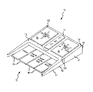
Figure 3 is a perspective view of a foot-activated controller that may be used
by the imaging systems of
Figures 1 and 2, with its first and second controller sections being in a
joined or coupled state.
Figure 4 is a perspective view of the foot-activated controller of Figure 3,
with its first and second
controller sections being in a separated or uncoupled state.
Figure 5 is a cutaway view of the foot-activated controller of Figure 3.
Figure 6 is a schematic of a representative wireless signal that may be used
by the foot-activated
controller of Figure 3.
DETAILED DESCRIPTION
One embodiment of an imaging system is illustrated in Figure 1 and is
identified by reference numeral 10.
The imaging system 10 may be used for any appropriate application, including
without limitation a medical
application. Therefore, the imaging system 10 may be referred to as a medical
imaging system 10.
The medical imaging system 10 includes an imaging assembly 12 and a table
assembly 30, each of
which may be of any appropriate size, shape, configuration, and/or type. The
imaging assembly 12 may include
any appropriate imaging equipment and any related components (e.g., for
providing an x-ray functionality (e.g.,
5
CA 02718416 2010-09-13
WO 2009/114365
PCT/US2009/036094
acquiring an x-ray image), for providing a tomography functionality (e.g.,
acquiring a tomography image), for
providing a fluoroscopy functionality (e.g., acquiring a fluoroscopy image),
store last image hold, magnification, and
any combination thereof). Although the medical imaging system 10 may be
configured for any appropriate medical
application, in one embodiment the medical imaging system 10 is adapted for
performing/facilitating the
performance of one or more urology procedures.
The table assembly 30 may include a table or a tabletop 32, a table tub 34,
and a table positioner 38.
The table 32 may be moved relative to the table tub 34 by the table positioner
38 in each of first and second
directions within a reference plane that at least generally coincides with a
supporting surface 33 of the table 32.
Double-headed arrow 50 in Figure 1 represents one direction in which the table
32 may be moved relative to the
table tub 34 within this reference plane, and which may define a longitudinal
dimension or axis (e.g., coinciding
with or defining the long axis of the supporting surface 33 of the table 32).
The table 32 may also be moved
relative to the table tub 34 in a direction that is orthogonal to the view
presented in Figure 1, and which may define
a lateral dimension (e.g., see Figure 2, which includes one double-headed
arrow 50 to define the longitudinal
dimension or axis, and which includes another double-headed arrow 50 to define
the lateral dimension or axis). A
patient would typically lie head-to-toe in the longitudinal dimension on the
supporting surface 33 of the table 32. If
the patient were lying on his/her back in this fashion, the patient's
shoulders would be spaced in the lateral
dimension.
The table positioner 38 may provide multiple movements or movement types for
the table 32. The table
positioner 38 may be configured to move the table 32 relative to the table tub
34 in the above-noted manner (e.g.,
in each of the longitudinal and lateral dimensions). The table positioner 38
may be configured to collectively move
the table 32 and the table tub 34 in the vertical dimension, and as indicated
by the double-headed arrow 54 (e.g.,
up and down relative to a floor 120, which may support one or more components
of the medical imaging system
10). The table positioner 38 may be configured to collectively move the table
32 and the table tub 34 at least
generally about an axis 46 that extends in the lateral dimension, that is
horizontally disposed, or both, and as
indicated by the double-headed arrow 52. This type of motion may be
characterized as changing an angle
between horizontal and the longitudinal dimension or axis of the supporting
surface 33 of the table 32. Another
characterization of this motion is that it is a "tilting" the table 52, for
instance a "longitudinal tilting" of the table 32
(e.g., raising the head and simultaneously lowering the feet of the patient;
lowering the head and simultaneously
raising the feet of the patient). Therefore, the axis 46 may be referred to as
a "tilt axis 46." The tilt axis 46 may be
disposed at any appropriate location in the vertical dimension and at any
appropriate location in the longitudinal
dimension of the table 32.
The table positioner 38 may be of any appropriate size, shape, configuration,
and/or type to move the
table 32 in any desired manner. In the illustrated embodiment, the table
positioner 38 includes a base 40 that is
disposed on the floor 120. The table positioner 38 utilizes a column 42 (e.g.,
the shaft of an appropriate cylinder)
that may be both extended and retracted to raise and lower, respectively, the
table 32 in the vertical dimension
(e.g., to move the table 32 along an axis corresponding with the double-headed
arrow 54). A joint 44 of any
appropriate type allows the table positioner 38 to move the table 32 at least
generally about the tilt axis 46. Part of
6
CA 02718416 2010-09-13
WO 2009/114365
PCT/US2009/036094
the table positioner 38 (not shown) may be located within the table tub 34 or
otherwise to move the table 32
relative to the table tub 34 in the above-noted longitudinal and lateral
dimensions (e.g., in accordance with the two
double-headed arrows 50 shown in Figure 2).
The medical imaging system 10 of Figure 1 includes a foot-activated controller
70 for controlling one or
more aspects of the operation of both the imaging assembly 12 and the table
positioner 38. Therefore, the foot-
activated controller 70 may be referred to as a multi-function controller. In
any case, any appropriate
communication link 110a may exist between the foot-activated controller 70 and
the table positioner 38. Similarly,
any appropriate communication link 110b may exist between the foot-activated
controller 70 and the imaging
assembly 12. The communication links 110a, 110b may be of a common or
different type. In one embodiment,
each communication link 110a, 110b is a wireless communication link.
A more detailed view of the medical imaging system 10 is presented in Figure
2. Here the imaging
assembly 12 includes camera equipment 14 (e.g., for acquiring an x-ray image,
for acquiring a tomography image,
for acquiring a fluoroscopy image, store last image hold, magnification, and
any combination thereof), a support
arm 16 for the camera equipment 14, and one or more monitors 18 (two shown)
for displaying an acquired image.
The lower portion of the table tub 34 is attached to a pedestal 36 in the
Figure 2 configuration. The table positioner
38 is not shown in Figure 2, but is able to move the table 32 relative to the
table tub 34 in each of the longitudinal
and lateral dimensions (double-headed arrows 50), is able to collectively move
the table 32 and table tub 34 in the
vertical dimension (double-headed arrow 54), and is able to collectively and
longitudinally tilt the table 32 and table
tub 34 at least generally about the tilt axis 46 (double-headed arrow 52).
The foot-activated controller 70 is operatively interconnected with each of
the table positioner 38 and the
imaging assembly 12 by a communication link 110. In accordance with the
foregoing, the communication link 110
may be of any appropriate type (e.g., wireless). Wireless methods can be RF
type (e.g., Bluetooth , Zigbee ),
light-based such as infrared, or sound-based (preferably in the inaudible
range, such as ultrasound). A separate
communication link 110 may be provided between the foot-activated controller
70 and each of the table positioner
38 and the imaging assembly 12 or otherwise. The medical imaging system 10 may
also include one or more
hand-activated controllers 62, where each such hand-activated controller 62 is
operatively interconnected with at
least one of the table positioner 38 and the imaging assembly 12 by a
communication link 64. Each such
communication link 64 may be of any appropriate type (e.g., wireless). A
separate communication link 64 may be
provided between any particular hand-activated controller 62 and each of the
table positioner 38 and the imaging
assembly 12 or otherwise. A separate hand-activated controller 62 could also
be provided for each of the table
positioner 38 and the imaging assembly 12 (not shown).
One embodiment of the foot-activated controller 70 is illustrated in more
detail in Figures 3-5. The foot-
activated controller 70 includes a first controller section 80 and a second
controller section 90, along with at least
one actuator 72. Multiple actuators 72 are utilized in the illustrated
embodiment, such as at least one first actuator
86, at least one second actuator 96, and at [east one third actuator 100. The
first controller section 80 includes a
first housing 82, while the second controller section 90 includes a second
housing 92. The first controller section
80 utilizes at least one first actuator 86, while the second controller
section 90 utilizes at least one second actuator
7
CA 02718416 2010-09-13
WO 2009/114365
PCT/US2009/036094
96. In one embodiment, each first actuator 86 is dedicated to communicating
with the imaging assembly 12, while
each second actuator 96 is dedicated to communicating with the table
positioner 38. In one embodiment, all first
actuators 86 are integrated with the first controller section 80, while all
second actuators 96 are integrated with the
second controller section 90.
Any appropriate number of first actuators 86 may be utilized by the first
controller section 80, and multiple
first actuators 86 may be disposed in any appropriate arrangement. In the
illustrated embodiment, one first
actuator 86 controls/activates an x-ray functionality (e.g., the acquisition
of an x-ray image), another first actuator
86 controls/activates a fluoroscopy functionality (e.g., the acquisition of a
fluoroscopy image), another first actuator
86 controls/establishes the selection of a magnification mode for the imaging
assembly 12, while another first
actuator 86 provides an image saving function. Each first actuator 86 may be
of any appropriate size, shape,
configuration, and/or type. In one embodiment, each first actuator 86 is in
the form of an on/off or two-position
switch. Therefore, each first actuator 86 may be characterized as being
dedicated to controlling an imaging
functionality.
Any appropriate number of second actuators 96 may be utilized by the second
controller section 90, and
multiple first actuators 96 may be disposed in any appropriate arrangement. In
the illustrated embodiment, one
second actuator 96 controls both the longitudinal and lateral position of the
table 32 relative to the table tub 34
(e.g., to control the movement of the table 32 in the direction of the double-
headed arrows 50 shown in Figure 2),
while another second actuator 96 controls both a position of the table 32 in
the vertical dimension (e.g., to control
the movement of the table 32 in the direction of the double-headed arrow 54
shown in Figure 2) and the tilt angle
of the table 32 (e.g., to control the movement of the table in the direction
of the double-headed arrow 52 shown in
Figure 2). Each second actuator 96 may be of any appropriate size, shape,
configuration, and/or type. In one
embodiment, each second actuator 86 is in the form of a four-position switch.
Therefore, each second actuator 96
may be characterized as being dedicated to controlling motion of the table 32.
The foot-activated controller 70 also includes at least one third actuator
100. Any appropriate number of
third actuators 100 may be utilized by the foot-activated controller 70. In
one embodiment, a single third actuator
100 is incorporated by the second controller section 90 and this third
actuator 100 controls the movement of at
least part of the imaging assembly 12 (e.g., movement of what may be
characterized as an "imaging chain," such
as a collective movement of an x-ray tube and receiver). Therefore, each third
actuator 100 may be characterized
as being dedicated to controlling motion of the imaging assembly 12.
Based upon the foregoing, each actuator 72 utilized by the first controller
section 80 (first actuators 86)
may be characterized as being dedicated to controlling the acquisition of an
image. Each actuator 72 utilized by
the second controller section 90 (second actuators 96 and third actuator 100)
may be characterized as being
dedicated to controlling motion of at least a portion of the medical imaging
system 10.
Each of the first housing 82 (first controller section 80) and the second
housing 92 (second controller
section 90) may be of any appropriate size, shape, configuration, and/or type.
The first housing 82 utilizes at least
one registration and/or locking member 84, while the second housing 92
utilizes at least one registration and/or
locking 94. Each of the first registration/locking member 84 and the second
registration/locking member 94 may
8
CA 02718416 2010-09-13
WO 2009/114365
PCT/US2009/036094
be of any appropriate size, shape, configuration, and/or type. Each first
registration/locking member and each
second registration/locking member 94 may be disposed in any appropriate
arrangement. Generally, each first
registration/locking member 84 may interface with a corresponding second
registration/locking member 94 to
provide an appropriate physical interconnection between the first controller
section 80 and the second controller
section 90, to limit relative movement between the first controller section 80
and second controller section 90 in at
least one direction or dimension, or both. In one embodiment, the first
controller section 80 and second controller
section 90 are moved vertically relative to each other to selectively
couple/uncouple the same.
The interconnection between the first controller section 80 and the second
controller section 90 is subject
to a number of characterizations. One is that the first controller section 80
and the second controller section 90
may be characterized as being detachably interconnected. Another is that the
first controller section 80 and the
second controller section 90 may be characterized as being interlocked (e.g.,
selectively). Another is that the first
controller section 80 and the second controller section 90 may be
characterized as being coupled (e.g.,
selectively). Yet another is that the first controller section 80 and the
second controller section 90 may be
characterized as being disposable in each of a joined, connected, or coupled
state and an un-joined, disconnected,
or uncoupled state. When the first controller section 80 and the second
controller section 90 are physically
interconnected, they may be collectively moved (e.g., along the floor 120).
When the first controller section 80 and
the second controller section 90 are disconnected, uncoupled, or separated
from each other, the first controller
section 80 and the second controller section 90 may be moved (e.g., along the
floor 120) independent of each
other to at least some extent.
The first controller section 80 and the second controller section 90 may be
disposed in any appropriate
position relative to each other when in a joined or coupled state. In the
illustrated embodiment, the second
controller section 90 defines an upper level for the foot-activated controller
70 when the first controller section 80
and the second controller section 90 are in a joined/coupled state, while the
first controller section 80 defines a
Lower level for the foot-activated controller 70 when the first controller
section 80 and the second controller section
90 are in a joined/coupled state. Therefore, each second actuator 96 may be
characterized as being disposed at a
higher elevation than each first actuator 86 when the first controller section
80 and the second controller section 90
are in a joined or coupled state. In one embodiment, the foot-activated
controller 70 is at least generally wedge-
shaped in a side view (Figure 5) and when the first controller section 80 and
the second controller section 90 are in
a joined or coupled state.
Based upon the foregoing, the foot-activated controller 70 may be operated
when disposed in each of two
different configurations. The first controller section 80 and the second
controller section 90 may be joined together
or coupled, and an operator (e.g., an attending physician) may independently
operate each of the various first
actuators 86, each of the various second actuators 96, and each of the various
third actuators 100. The foot-
activated controller 70 may also be configured such that the first controller
section 80 is separated or uncoupled
from the second controller section 90, such that the first controller section
80 and the second controller section 90
may be separately positioned to at least some extent, and where an operator
(e.g., an attending physician) may
independently operate each of the various first actuators 86, each of the
various second actuators 96, and each of
9
CA 02718416 2010-09-13
WO 2009/114365
PCT/US2009/036094
the various third actuators 100. That is, the first controller section 80 and
the second controller section 90 may be
characterized as being selectively joined/coupled or separated/uncoupled as
desired.
The foot-activated controller 70 may utilize one or more alarms of any
appropriate size, shape,
configuration, and/or type (e.g., optical, audible). At least one range alarm
102 and at least one locating alarm 104
may be utilized by the foot-activated controller 70. In one embodiment, each
of the first controller section 80 and
the second controller section 90 incorporates at least one range alarm 102 and
at least one locating alarm 104.
Each range alarm 102 may be activated when a corresponding portion of the foot-
activated controller 70 is located
outside of a predetermined range from one or more of the imaging assembly 12
and the table positioner 38. Each
locating alarm 104 may be activated by an individual in any appropriate manner
(e.g., by incorporating one or more
i0 switches at an appropriate location of the medical imaging system 10) in
an attempt to locate a corresponding
portion of the foot-activated controller 70.
As noted above, the foot-activated controller 70 may communicate wirelessly
with one or both of the
imaging assembly 12 and the table positioner 38. In this case, it may be
desirable to reduce the potential that the
foot-activated controller 70 will communicate with anything other than its
associated medical imaging system 10.
For instance, consider the case where one medical imaging system 10 is located
in one room, and another
medical imaging system 10 is located in an adjacent room. Each medical imaging
system 10 may be configured to
utilize wireless communications in a manner that reduces the potential for the
foot-activated controller 70 from one
of these medical imaging systems 10 being able to communicate with the imaging
assembly 12 and/or table
positioner 38 of the other adjacent medical imaging system 10. Figure 6
illustrates a representative wireless
communication for this type of situation.
A wireless signal 112 is illustrated in Figure 6 and may be characterized as
including an identifier
segment 114 and a command segment 116. The identifier segment 114 may be
unique to one of a plurality of
medical imaging systems 10. Therefore, a first medical imaging system 10 would
have a different identifier
segment 114 than a second medical imaging system 10. Each actuator 72 of one
medical imaging system 10 may
communicate with the corresponding imaging assembly 12 and/or table positioner
38 by sending one or more
wireless signals 112 (e.g., using a common identifier segment 114), whereas
each actuator 72 of another medical
imaging system 10 may communicate with either its corresponding imaging
assembly 12 and/or table positioner 38
by sending one or more wireless signals 112 (e.g., using a different
identifier segment 114).
The foregoing description of the present invention has been presented for
purposes of illustration and
description. Furthermore, the description is not intended to limit the
invention to the form disclosed herein.
Consequently, variations and modifications commensurate with the above
teachings, and skill and knowledge of
the relevant art, are within the scope of the present invention. The
embodiments described hereinabove are
further intended to explain best modes known of practicing the invention and
to enable others skilled in the art to
utilize the invention in such, or other embodiments and with various
modifications required by the particular
application(s) or use(s) of the present invention. It is intended that the
appended claims be construed to include
alternative embodiments to the extent permitted by the prior art.