Note: Descriptions are shown in the official language in which they were submitted.
CA 02718728 2011-12-21
CARTON WITH HANDLE
Background of the Disclosure
[00011 The present disclosure generally relates to cartons for holding and
dispensing
beverage containers or other types of articles. More specifically, the present
invention
relates to cartons having a reinforced handle.
Summary of the Disclosure
[0002] In general, one aspect of the invention is directed to a carton for
containing a
plurality of articles. The carton comprises a plurality of panels that extends
at least
partially around an interior of the carton. The plurality of panels comprises
a first top
panel, a second top panel, a bottom panel, a first side panel, and a second
side panel.
The first top panel and the second top panel being at least partially
overlapped to
form a top wall of the carton. At least two end flaps respectively foldably
attached to
respective panels of the plurality of panels, wherein the end flaps are
overlapped with
respect to one another and thereby at least partially form a closed end of the
carton. A
handle in the top wall of the carton comprises a first handle section in the
first top
panel, a second handle section in the second top panel, and a handle
reinforcement
flap foldably connected to at least one of the first top panel and the second
top panel.
The first handle section, the second handle section, and the handle
reinforcement flap
are placed in overlapping relationship to form the handle.
[0003] In another aspect, the disclosure is generally directed to a blank for
forming a
carton. The blank comprises a plurality of panels comprising a first top
panel, a
second top panel, a bottom panel, a first side panel, and a second side panel.
At least
two end flaps are respectively foldably attached to respective panels of the
plurality
of panels. The blank comprises features in the first top panel and the second
top
panel, wherein the features are for cooperating to at least partially define a
handle in a
carton erected from the blank. The features comprise a first handle section in
the first
top panel, a second handle section in the second top panel, and a handle
reinforcement flap foldably connected to at least one of the first top panel
and the
second top panel.
I
CA 02718728 2011-12-21
[0004] In another aspect, the disclosure is generally directed to a method of
assembling a carton. The method comprises providing a blank comprising a
plurality
of panels comprising a first top panel, a second top panel, a bottom panel, a
first side
panel, and a second side panel. The first top panel and the second top panel
are at
least partially overlapped to form a top wall of the carton. At least two end
flaps are
respectively foldably attached to respective panels of the plurality of
panels. The first
top panel comprises a first handle section. The second top panel comprises a
second
handle section. A handle reinforcement flap is foldably connected to at least
one of
the first top panel and the second top panel. The method further comprises
forming a
top wall of the carton by at least partially overlapping the first top panel
and the
second top panel. The forming the top wall comprises forming a handle in the
top
wall by at least partially positioning the first handle section, the second
handle
section, and the handle reinforcement flap in an overlapping relationship to
form the
handle.
[0005] In another aspect, the disclosure is generally directed to a carton for
containing a plurality of articles. The carton comprises a plurality of panels
that
extends at least partially around an interior of the carton. The plurality of
panels
comprises a first top panel, a second top panel, a bottom panel, a first side
panel, and
a second side panel. The first top panel and the second top panel being at
least
partially overlapped to form a top wall of the carton. A handle is in the top
wall of the
carton. The handle comprises a first handle section, a second handle section,
and a
handle reinforcement flap foldably connected to at least one of the first top
panel and
the second top panel.
[0006] According to one aspect of the present invention there is provided a
carton
for containing a plurality of articles, the carton comprising a plurality of
panels that
extends at least partially around an interior of the carton, the plurality of
panels
comprises a first top panel, a second top panel, a bottom panel, a first side
panel, and
a second side panel, the first top panel and the second top panel being at
least
partially overlapped to form a top wall of the carton; and a handle in the top
wall of
the carton, the handle comprising a first handle section in the first top
panel, a second
handle section in the second top panel, and a handle reinforcement flap, the
first
handle section and the second handle section each respectively at least
partially
defining an opening and comprising a comfort panel adjacent the opening, the
handle
reinforcement flap being foldably connected to the second top panel by first
and
second fold lines that are spaced apart from one another, the handle
reinforcement
2
CA 02718728 2011-12-21
flap and the second handle section each respectively comprising a free edge
defining
a protrusion, and the first handle section, the second handle section, and the
handle
reinforcement flap being in overlapping relationship to form the handle such
that the
protrusion of the handle reinforcement flap is superposed with the comfort
panel of
the second handle section and the protrusion of the second handle section is
superposed with the comfort panel of the first handle section.
[0006.1] According to a further aspect of the present invention there is
provided a
blank for forming a carton comprising a plurality of panels comprising a first
top
panel, a second top panel, a bottom panel, a first side panel, and a second
side panel;
at least two end flaps respectively foldably attached to respective panels of
the
plurality of panels; features in the first top panel and the second top panel,
wherein
the features are for cooperating to at least partially define a handle in a
carton erected
from the blank, the features comprise a first handle section in the first top
panel, a
second handle section in the second top panel, and a handle reinforcement
flap; the
second handle section having a length extending between opposite ends of the
second
handle section, and a width that extends crosswise to, and is smaller than,
the length;
the handle reinforcement flap comprising a handle reinforcement section
positioned
between end portions of the handle reinforcement flap, and the end portions
respectively being foldably connected to the second top panel by first and
second fold
lines that are spaced apart from one another; and a line for separation, for
allowing an
edge of the handle reinforcement section to be separated from an edge of the
second
handle section, the line for separation extending along substantially all of
the length
of the second handle section from an end of the first fold line to an end of
the second
fold line, wherein the line of separation is a tear line comprising three
curves.
[0006.2] According to another aspect of the present invention there is
provided a blank
for forming a carton comprising a plurality of panels comprising a first top
panel, a
second top panel, a bottom panel, a first side panel, and a second side panel;
features
in the first top panel and the second top panel, wherein the features are for
cooperating to at least partially define a handle in a carton erected from the
blank, the
features comprise a first handle section in the first top panel, a second
handle section
in the second top panel, and a handle reinforcement flap; the first handle
section and
the second handle section each respectively at least partially defining an
opening and
comprising a comfort panel adjacent the opening, the handle reinforcement flap
comprising a handle reinforcement section positioned between end portions of
the
2a
CA 02718728 2011-12-21
handle reinforcement flap, and the end portions respectively being foldably
connected
to the second top panel by first and second fold lines that are spaced apart
from one
another; and a line for separation, for allowing an edge of the handle
reinforcement
section to be separated from an edge of the second handle section, the edge of
the
handle reinforcement flap and the edge of the second handle section each
respectively
comprising a protrusion defined by the line for separation, wherein the
features are
configured such that the protrusion of the handle reinforcement flap is for
being
superposed with the comfort panel of the second handle section and the
protrusion of
the second handle section is for being superposed with the comfort panel of
the first
handle section when the handle is assembled.
2b
CA 02718728 2010-09-16
WO 2009/117562 PCT/US2009/037642
[0007] Those skilled in the art will appreciate the above stated advantages
and other
advantages and benefits of various additional embodiments reading the
following
detailed description of the embodiments with reference to the below-listed
drawing
figures.
Brief Description of the Drawings
[0008] According to common practice, the various features of the drawings
discussed
below are not necessarily drawn to scale. Dimensions of various features and
elements in the drawings may be expanded or reduced to more clearly illustrate
the
embodiments of the disclosure.
[0009] FIG. 1 is a plan view of an exterior surface of a blank used to form a
carton
according to a first embodiment of the present disclosure.
[0010] FIG. 2 is a view of an interior surface of the blank of FIG. 1 formed
into a
partially assembled condition.
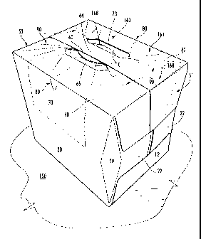
[0011] FIG. 3 is a perspective of the carton in a further partially assembled
condition.
[0012] FIG. 4 is side perspective view of the carton.
[0013] FIG. 5 is end perspective view of the carton.
[0014] FIG. 6 is a top view of the carton.
[0015] FIG. 7 is a side view of the carton.
[0016] FIG. 8 is a side view of the carton with a dispenser opened and a
container
removed.
[0017] FIG. 9 is a plan view of an exterior surface of a blank used to form a
carton
according to a second embodiment of the present disclosure.
[0018] Corresponding parts are designated by corresponding reference numbers
throughout the drawings.
3
WCSR 4093135v1
CA 02718728 2010-09-16
WO 2009/117562 PCT/US2009/037642
Detailed Description of the Exemplary Embodiments
[0019] The present invention generally relates to cartons that contain
articles such as
containers, bottles, cans, etc. The articles can be used for packaging food
and
beverage products, for example. The articles can be made from materials
suitable in
composition for packaging the particular food or beverage item, and the
materials
include, but are not limited to, aluminum and/or other metals; glass; plastics
such as
PET, LDPE, LLDPE, HDPE, PP, PS, PVC, EVOH, and Nylon; and the like, or any
combination thereof.
[0020] Cartons according to the present invention can accommodate articles of
any
shape. For the purpose of illustration and not for the purpose of limiting the
scope of
the invention, the following detailed description describes beverage
containers (e.g.,
aluminum beverage cans) as disposed within the carton embodiments. In this
specification, the terms "lower," "bottom," "upper" and "top" indicate
orientations
determined in relation to fully erected and upright cartons.
[0021] FIG. 1 is a plan view of the exterior side 3 of a blank 5 used to form
a carton
150 (FIGS. 4-8) according to a first exemplary embodiment of the disclosure.
The
carton 150 can be used to house a plurality of articles such as containers C
(Fig. 8). In
the illustrated embodiment, the carton 150 has two dispensers, generally
indicated at 7
(Fig. 5), formed in the carton for allowing access to the containers C. In the
illustrated embodiment, the carton 150 is sized to house twenty-four
containers C in
two layers in a 3x4x2 arrangement, but it is understood that the carton may be
sized
and shaped to hold containers of a different or same quantity in more than or
less than
two layers and/or in different row/column arrangements (e.g., 3x5x2, 3x6,
2x6x2,
3x5, 2x9, 2x6, 3x4, etc.). In the illustrated embodiments, the containers C
are twelve
ounce generally cylindrical beverage cans. Other container types, as well as
other
articles, may also be accommodated in cartons constructed according to the
present
invention. In the illustrated embodiment, the carton 150 includes a handle,
generally
indicated at 160 for grasping and carrying the carton. As will be discussed
below in
more detail, the handle 160 is formed from various features in the blank 5.
4
WCSR 4093135v1
CA 02718728 2010-09-16
WO 2009/117562 PCT/US2009/037642
[0022] The blank 5 has a longitudinal axis L1 and a lateral axis L2. In the
embodiment of FIG. 1, the blank 5 has at least partial symmetry about a
longitudinal
center line CL and about a transverse center line CT. Therefore, certain
elements in
the drawing figures have similar or identical reference numerals in order to
reflect the
whole and/or partial longitudinal and transverse symmetries of the blank 5.
[0023] Referring to FIG. 1, the blank 5 comprises a bottom panel 10 foldably
connected to a first side panel 20 at a first lateral fold line 21. A second
side panel 26
is foldably connected to the bottom panel at a second lateral fold line 27. A
first top
panel 30 is foldably connected to the first side panel 20 at a third lateral
fold line 31.
A second top panel 40 is foldably connected to the second side panel 26 at a
fourth
lateral fold line 41.
[0024] The bottom panel 10 is foldably connected to first and second bottom
end
flaps 12. The first side panel 20 is foldably connected to a first and second
side end
flap 22. The second side panel 26 is foldably connected to a first and second
side end
flap 28. The first top panel 30 is foldably connected to a first and second
top end flap
32. The second top panel 40 is foldably connected to a first and second top
end flap
42. When the carton 150 is erected, the top and bottom end flaps 12, 32, 42
and side
end flaps 22, 28 at a first end of the blank 5 close a first end 51 of the
carton, and the
top and bottom end flaps and side end flaps at a second end of the blank close
a
second 53 end of the carton. In accordance with an alternative embodiment of
the
present invention, different flap arrangements can be used for closing the
ends of the
carton 150.
[0025] In the illustrated embodiment, the bottom end flaps 12 are foldably
connected
to opposite ends of the bottom panel 10 at longitudinal fold lines 11. The
side end
flaps 22, 28 are connected at each end of each of the first and second side
panel 20, 26
at the diamond-shaped corner panels 50. The first top end flaps 32 are
connected to
each end of the first top panel 30 at longitudinal fold lines 33. The second
top end
flaps 42 are connected to each end of the second top panel 40 at longitudinal
fold lines
43. The longitudinal fold lines 11, 33, 43 may be, for example, substantially
straight,
or offset at one or more locations to account for blank thickness or for other
factors.
WCSR 4093135v1
CA 02718728 2010-09-16
WO 2009/117562 PCT/US2009/037642
[0026] In one embodiment, the blank 5 includes a first dispenser panel 70 that
is
formed by a first tear line 73. The first dispenser panel 70 has a first
portion 75 in
first top panel 30 and a second portion 77 in the first side panel 20. A
second
dispenser panel 70 is similarly shaped as the first dispenser panel, but is
formed in the
second top panel 40 and the second side panel 26. One or both of the dispenser
panels
70 could be omitted from the blank 5 without departing from the disclosure.
Further,
one or both of the dispenser panels 70 could be otherwise shaped, arranged,
and/or
configured without departing from the disclosure.
[0027] A plurality of stress-diverting score lines 80 are formed in the
dispenser panel
70. A plurality of stress-diverting score lines 90 are formed in the first and
second top
panels 30 and 40. In the illustrated embodiment, the stress-diverting score
lines 80,
90 are formed in groups of three adjacent score lines. The score lines 80, 90
of each
group are oblique lines. The score lines 90 in the first and second top panel
30, 40
diverge as the score lines extend radially outward from a central portion of
the top
panel. The score lines 80 in the dispenser panel converge as the score lines
extend
radially outward from a central portion of the top panel to a respective
lateral fold
line 31, 41. The stress-diverting score lines 80 and 90 increase the carrying
capacity
of the carton 150 by distributing stress as the carton 150 is lifted by its
handle 160,
shown in FIGS. 2-7.
[0028] The stress-diverting score lines 80 and 90 are grouped in plural sets
of
non-parallel lines. There are two sets of score lines 80 and four sets of
score lines 90,
as shown in FIGS. 1 and 6. Each set of score lines 80 are fully contained
within a
dispenser panel 70. Each set of these score lines 80 include a group of three
non-parallel lines on each top panel 30 and 40 that converge toward at least
one
curved score line in a side panel 20, 26. These three non-parallel lines have
substantially the same length and are spaced apart by substantially equal
angles a,
preferably less than about twenty degrees. The outer score lines of the three
non-
parallel lines of each set of score lines 80 are adjacent to and in alignment
with ends
of a curved score line and the side panel 20. Each set of score lines 90
includes a
group of three non-parallel lines. These non-parallel lines are spaced apart
by
substantially equal angles fl, preferably less than about twenty degrees. The
center
6
WCSR 4093135v1
CA 02718728 2010-09-16
WO 2009/117562 PCT/US2009/037642
line of each set of score lines 90 is directed toward a corner of the carton
150 and has
a substantially greater length than the outer two score lines of each set. The
score lines
80, 90 could be otherwise shaped, arranged, and/or positioned, or the score
lines could
be omitted, without departing from the disclosure.
[0029] In the illustrated embodiment, a handle reinforcement flap 46 is
foldably
connected to the second top panel 40 and the top end flaps 42 at lateral fold
lines 48.
The handle reinforcement flap 46 is removably attached to the second top panel
40 at
a tear line 110 that extends between the lateral fold lines 48. Alternatively,
the tear
line 110 could be a cut line or other line of weakening that allows separation
of the
reinforcement flap 46 from the second top panel 40. The handle reinforcement
flap
46 has a reinforcement handle section 62 defined by the portion of the handle
reinforcement flap between a lateral edge 49 of the blank 5 and the tear line
110. The
handle reinforcement flap 46 includes respective reinforcement end portions 63
at
respective ends of the reinforcement handle section 62. Each of the
reinforcement
end portions 63 is foldably connected to the second top panel 40 and one of
the end
panels 42 at the lateral fold lines 48. The handle reinforcement flap 46 could
be
otherwise shaped, arranged, and/or configured without departing from the
disclosure.
[0030] The second top panel 40 has a second handle section 60 formed in a
central
portion of the second top panel. The second handle section 60 is adjacent the
reinforcement handle section 62 and an opening 65 in the second top panel. The
second handle section is partially define by respective cuts 118 that extend
from the
opening 65 into the second top panel 40. The second handle section 60 includes
a
comfort panel 67 adjacent the opening 65. The comfort panel 60 is foldably
connected to the second handle section 60 at a lateral fold line 69. The
second handle
section 60 could be otherwise shaped, arranged, and configured without
departing
from the disclosure.
[0031] The first top panel 30 has a first handle section 64 that is similar in
shape as
the second handle section 60 and an opening 85. The first handle section 64 is
at least
partially defined by the space between the opening 85 and tear lines 124 on
one side
of the first handle section and the lateral edge 77 of the blank 5 on the
other side of
the first handle section. The first handle section 64 has a comfort panel 79
adjacent
7
WCSR 4093135x1
CA 02718728 2010-09-16
WO 2009/117562 PCT/US2009/037642
the opening 85. The first handle section 64 could be otherwise shaped,
arranged,
and/or configured without departing from the disclosure. The handle sections
60, 62
and 64 overlap in the erected carton to form a multi-ply carton handle 160, as
shown
in FIGS. 4-8.
[0032] Still referring to FIG. 1, adhesives 102, 104 and 106, which may be in
the
form of glue strips, for example, may be applied to the surface of the blank 5
to
facilitate erection of the carton 150. The adhesives 102, 104 and 106
illustrated in
FIG. 1 are applied to the interior surface of the blank 5, although other
arrangements
and adhesive forms are possible.
[0033] In accordance with an exemplary embodiment, a method of forming the
carton
150 from the blank 5 will now be described with reference to FIGS. 1-4. As
shown in
Fig. 2, the blank 5 is positioned with an interior surface 4 facing upward.
The handle
reinforcement flap 46 is folded about fold lines 48 in the direction of arrow
Al. The
handle reinforcement flap 46 is placed in face-to-face contact with the second
top
panel 40 and the end flaps 42. The reinforcement handle section 62 is
adhesively
connected to the second handle section 60 by adhesive strip 104. The
reinforcement
end portions 63 are adhesively connected to the second top panel 40 and the
end flaps
42 by the adhesive strips 102. Also, the side panels 20, 26 are folded
upwardly about
fold lines 21, 27 relative to the bottom panel 10 and generally in the
direction of
arrows A2.
[0034] As shown in Fig. 3, the first top panel 30 is positioned in the
direction of
arrow A3 to partially overlap the second top panel 40 and form the top wall
161 of the
carton 150. The first handle section 64 is placed in face-to-face contact with
the
second handle section 62 and they are adhesively secured by the adhesive strip
106.
In this manner the reinforcement handle section 62 that is secured to the
second
handle section 60 and the first handle section 64 that is secured to the
second handle
section 60 form the multi-ply handle 160. Securing the first top panel 30 to
the
second top panel 40 forms a generally open-ended sleeve 153 (Fig. 3).
[0035] In the illustrated embodiment, one end of the sleeve 153 is closed by
respectively overlapping and adhering the side end flaps 22, 28 and the top
and
bottom end flaps 12, 32, 42 at one end of the sleeve after the containers C
are inserted
8
WCSR 4093135v1
CA 02718728 2010-09-16
WO 2009/117562 PCT/US2009/037642
into the carton. The second end of the sleeve is closed by respectively
overlapping
and adhering the side end flaps 22, 28 and top and bottom end flaps 12, 32, 42
at the
second end of the sleeve. Once the blank 5 is formed into the sleeve 153, the
containers C may be loaded in the carton 150 from either end and then the ends
may
be closed. Alternative loading and closing steps may be used without departing
from
the scope of this invention.
[0036] The overlapping handle sections 60, 62 and 64 form the multi-ply handle
160
in the top wall 161 of the carton 150 for grasping and carrying the carton.
The
elongate structure of the handle 160 acts to distribute the stresses of
lifting along a
greater surface of the paperboard forming the top of the carton 150. Openings
65, 85
on either side of the handle 160 also provide a convenient starting point for
initiating
opening of the dispenser sections 70. In the illustrated embodiment, the
handle 160
includes a three-ply section 168 that includes the overlapped handle sections
60, 62,
64 and the overlapped portions of the first top panel 30, second top panel 40,
and
reinforced end portions 63 of the handle reinforcement flap 46. The three ply
section
168 extends across the length of the overlapped top panel 30, 40 and at least
partially
into the closed ends of the carton 150. In the closed ends of the carton 150,
the three-
ply section 168 includes overlapped top end flaps 32, 42 and the reinforced
end
portions 63 of the handle reinforcement flap. The three-play section 168 of
the handle
160 could be otherwise shaped, arranged, and/or configured without departing
from
the disclosure.
[0037] The dispenser sections 70 are located primarily in the side panels 20,
remote
from areas of the top and ends of the carton comprising the overlapping handle
sections 60, 62 and 64. This placement reduces the adverse effect of the score
lines
defining the perimeters of the dispenser sections 70 have on the strength of
the handle
160.
[0038] FIG. 5 shows one end of the carton 150 and FIG. 6 shows the top of the
carton
150. As shown in FIG. 6, the curved cuts 118 and 124 at the ends of the
respective
handle sections 60, 64 extend from a respective opening 65, 85 to an end
portion 119,
125 that is positioned to extend inward toward the three-ply section 168 of
the handle
160. Therefore, if the carton 150 tears at the ends of the handle sections 60,
62 and 64
9
WCSR 4093135v1
CA 02718728 2010-09-16
WO 2009/117562 PCT/US2009/037642
during lifting by the handle 160, the tear will be directed inwardly toward
the
reinforced multi-ply section 168 of the handle 160.
[0039] Referring to FIGS. 7 and 8, the carton 150 can be opened at one side by
tearing the carton at tear line 73 to remove the dispenser panel 70. One or
both of the
dispenser panels 70 can be removed by grasping at a respective opening 65, 85
and
tearing at tear line 73. Containers C in the carton interior can then be
accessed through
the resultant dispenser opening 180. The dispenser opening 180 includes
portions of
the side panels 20, 26 and portions of the top panels 30, 40. The dispenser
opening
180 and dispenser panel 70 could be larger or smaller than illustrated and
described
herein. In the illustrated embodiment, the carton 150 accommodates twenty-four
containers C in a 3 x 4 x 2 (three columns, four rows and two tiers)
arrangement,
although other container arrangements can be accommodated according to the
principles of the present invention. As shown in Fig. 8, the upper tier of
containers C
rest on a separator pad 190. For example, the dispenser panel 70 and dispenser
opening 180 could extend in the side panel 20, 26 to below the separator pad
190 so
that containers C in the bottom tier can be accessed through the dispenser
opening.
[0040] According to the above embodiment, the stress-diverting score lines 80
and 90
and the position and shape of the dispenser sections 70 provide increased
strength to
the handle 160. The elongate shape of the handle 160 further distributes
lifting stress
throughout the carton 150.
[0041] FIG. 9 shows an exterior surface 203 of a blank 205 used to form a
carton (not
shown) according to a second embodiment of the disclosure. The blank 205 has
similar features as the blank 5 of the first embodiment. Accordingly, similar
or
identical features of the embodiments are provided with like or similar
reference
numbers. The blank 205 of the second embodiment includes two stress-diverting
score lines 80a, 80b in each of the side panels 20, 26. In the illustrated
embodiment,
the score lines 80a, 80b are generally V-shaped and parallel. The score lines
80a, 80b
are centered on the longitudinal centerline CL but the score lines could be
otherwise
shaped, arranged, and/or omitted. The blank 205 could have other features that
are
like or different than the first embodiment without departing from the
disclosure.
WCSR 4093135v1
CA 02718728 2010-09-16
WO 2009/117562 PCT/US2009/037642
[0042] The blanks according to the present disclosure can be, for example,
formed
from coated paperboard and similar materials. For example, the interior and/or
exterior sides of the blanks can be coated with a clay coating. The clay
coating may
then be printed over with product, advertising, price coding, and other
information or
images. The blanks may then be coated with a varnish to protect any
information
printed on the blank. The blanks may also be coated with, for example, a
moisture
barrier layer, on either or both sides of the blank. In accordance with the
above-
described embodiments, the blanks may be constructed of paperboard of a
caliper
such that it is heavier and more rigid than ordinary paper. The blanks can
also be
constructed of other materials, such as cardboard, hard paper, or any other
material
having properties suitable for enabling the carton to function at least
generally as
described herein. The blanks can also be laminated or coated with one or more
sheet-
like materials at selected panels or panel sections.
[0043] In accordance with the above-described embodiments of the present
disclosure, a fold line can be any substantially linear, although not
necessarily
straight, form of weakening that facilitates folding therealong. More
specifically, but
not for the purpose of narrowing the scope of the present disclosure, fold
lines
include: a score line, such as lines formed with a blunt scoring knife, or the
like,
which creates a crushed portion in the material along the desired line of
weakness; a
cut that extends partially into a material along the desired line of weakness,
and/or a
series of cuts that extend partially into and/or completely through the
material along
the desired line of weakness; and various combinations of these features.
[0044] As an example, a tear line can include: a slit that extends partially
into the
material along the desired line of weakness, and/or a series of spaced apart
slits that
extend partially into and/or completely through the material along the desired
line of
weakness, or various combinations of these features. As a more specific
example, one
type tear line is in the form of a series of spaced apart slits that extend
completely
through the material, with adjacent slits being spaced apart slightly so that
a nick (e.g.,
a small somewhat bridging-like piece of the material) is defined between the
adjacent
slits for typically temporarily connecting the material across the tear line.
The nicks
are broken during tearing along the tear line. The nicks typically are a
relatively small
11
WCSR 4093135v1
CA 02718728 2011-12-21
percentage of the tear line, and alternatively the nicks can be omitted from
or torn in a
tear line such that the tear line is a continuous cut line. That is, it is
within the scope
of the present disclosure for each of the tear lines to be replaced with a
continuous
slit, or the like. For example, a cut line can be a continuous slit or could
be wider than
a slit without departing from the present disclosure.
[0045] The above embodiments may be described as having one or more panels
adhered together by glue during erection of the carton embodiments. The term
"glue"
is intended to encompass all manner of adhesives commonly used to secure
carton
panels in place.
[0046] The foregoing description of the disclosure illustrates and describes
various
exemplary embodiments. The scope of the claims should not be limited by the
preferred embodiments set forth in the examples, but should be given the
broadest
interpretation consistent with the description as a whole. It is intended that
all matter
contained in the above description or shown in the accompanying drawings shall
be
interpreted as illustrative and not in a limiting sense. Additionally, the
disclosure
shows and describes only selected embodiments of the disclosure, but the
disclosure
is capable of use in various other combinations, modifications, and
environments and
is capable of changes or modifications within the scope of the inventive
concept as
expressed herein, commensurate with the above teachings, and/or within the
skill or
knowledge of the relevant art. Furthermore, certain features and
characteristics of
each embodiment may be selectively interchanged and applied to other
illustrated and
non-illustrated embodiments of the disclosure.
12