Note: Descriptions are shown in the official language in which they were submitted.
CA 02718929 2010-10-28
1
COUPLING APPARATUS
This is a divisional application of Canadian Patent Application Se.lal No.
2,426,076 filed on October 16, 2001.
The present invention relates to coupling apparatus for coupling a
downhole tubular (such as a borehole casing) to a pump, conventionally
known as a circulating head. The invention also relates to a method of
pumping fluid into a downhole tubular, and to a method of drilling.
It should be understood that the expression uthe invention" and the like used
herein may refer to subject-matter claimed in either the parent or the
divisional
applications.
=
A conventional circulating head is described by LeFleur et al in US-A-
5,282,653, US-A-5,152,554 and US-A-5,348,351. As described by
LeFleur et al, when casing is being run in connection with the drilling of
an oil or gas well, it sometimes becomes necessary to connect surface
pumping equipment to circulate drilling fluid down the well. Typically,
this need arises when a tight spot is encountered and drilling fluid is
circulated down the well to run the casing past the tight spot and avoid
the need for removing the casing and redrilling the hole.
The circulating head described by LeFleur et al uses a segmented ring of
eight dogs to lock a cylindrical member in place. The dogs are fixed in
place by rotating a bottom end cap.
This arrangement suffers from a number of problems. Firstly the
apparatus has a large number of working parts. Secondly it can be
difficult and time consuming to rotate the bottom end cap,
An object of the invention is to address these problems or at least to
provide the public with a useful alternative.
According to a first aspect of the invention there is provided apparatus for
coupling a downhole tubular to a pump, the apparatus comprising: a body
CA 02718929 2010-10-28
= la
portion having a bore; a locking assembly comprising at least one locking
member pivotally mounted to the body portion by a pivot member so as to permit
the locking member to be pivoted between an open position in which the
downhole tubular can be inserted into the bore of the body portion, and a
closed
CA 02718929 2010-10-28
,
2
position in which the locking member engages the downhole tubular so as
to lock the downhole tubular in the bore of the body portion; and fixing
means for fixing the locking member in the closed position.
The invention provides a simple construction which enables the pump and
tubular to be easily and quickly connected.
Preferably the locking assembly comprises a pair of locking members
pivotally mounted to the body portion at a substantially common pivot
point.
Typically the apparatus further comprises one or more pivot pins pivotally
mounting the locking member(s) to the body portion.
Any suitable means may be provided for fixing the locking member(s) in
the closed position. In a preferred embodiment the fixing means
comprises a lever clamp mechanism.
Typically the body portion comprises an upwardly directed locking surface
which engages a locking surface of the locking member(s).
In the arrangement of LeFleur et al the body of the apparatus has a
radially outer ring with an upper surface. The dogs are secured to the ring
by screws, which engage the upper surface of the ring. A problem with
this arrangement is that the screws are not sufficiently strong to enable
the apparatus to support a heavy weight.
In accordance with a second aspect of the invention there is provided
apparatus for coupling a downhole tubular to a pump, the apparatus
comprising: a body portion having a bore and a locking surface which is
upwardly directed, when in use; a 'locking assembly comprising at least
one unitary locking member having first and second locking surfaces, the
locking member being movably mounted on the body portion so
CA 02718929 2010-10-28
WO 02/37015
PCT/NZ01/00227
3
as to permit the locking member to be moved between an open position in
which the downhole tubular can be inserted into the bore of the body
portion, and a closed position in which the first locking surface engages
the downhole tubular so as to lock the downhole tubular in the bore of
the body portion and the second locking surface engages the upwardly
extending locking surface of the body portion so as to secure the locking
member to the body portion; and fixing means for fixing the locking
member in the closed position.
The upwardly directed locking surface directly engages the locking
member, in contrast to the system of LeFleur in which the upwardly
directed surface of the ring engages the screw. This provides a more
secure connection. Preferably the connection is strong enough to enable
part of the full weight of the downhole to be lifted by lifting the body
portion.
Typically the locking surface of the body portion is substantially horizontal
when in use (ie the surface is directed substantially vertically). In other
words, the normal to the locking surface is substantially parallel to the
direction of insertion of the downhole tubular. Alternatively the locking
surface of the body portion may have a positive or negative camber.
Preferably the body portion has an outwardly directed projection (eg a
flange) whose upper surface provides the upwardly directed locking
surface, and the locking member is mounted about the projection.
Typically the locking member has a recess which receives the projection.
According to a third aspect of the invention there is provided apparatus
for coupling a downhole tubular to a pump, the apparatus comprising: a
body portion having a bore; a locking assembly for locking the downhole
tubular in the bore of the body portion; and an annular sealing member
mounted within the bore of the body portion and having a lower surface
which engages an upper surface of the downhole tubular when the
CA 02718929 2010-10-28
=
WO 02/37015
PCT/NZ01/00227
4
downhole tubular is received in the bore of the body portion, wherein the
body portion and an upper surface of the annular sealing member are
arranged so as to at least partially define a chamber which receives high
pressure fluid in use so as to force the annular sealing member into
engagement against the upper surface of the downhole tubular.
The third aspect of the invention provides a secure seal which reduces the
risk of fluid leakage during a pumping operation. A pressure difference is
set up across the annular sealing member, when in use, so as to increase
the integrity of the seal.
The sealing member may be rigidly fixed to the bore of the body portion,
and may flex in response to the fluid pressure so as to force the annular
sealing member against the upper surface of the downhole tubular.
However preferably the sealing member is slidably mounted in the bore so
as to permit the sealing member to translate into sealing engagement with
the upper surface of the downhole tubular.
Preferably resilient means (for instance springs) are provided to resiliently
90 bias the annular sealing member towards the upper surface of the
downhole tubular.
Preferably the annular sealing member has an upwardly directed flange
which further defines the chamber.
Preferably a resilient sealing member is provided to ensure a secure seal.
The resilient sealing member may be provided as a separate item, or the
annular sealing member may itself be formed of resilient material. The
resilient sealing member may engage the top of the downhole tubular
(providing a top face seal), the outside of the downhole tubular (providing
an external seal), the internal bore of the downhole tubular (providing an
internal seal), or all three. Where an internal or external seal is provided,
CA 02718929 2010-10-28
= ,
. =
WO 02/37015
PCT/NZ01/00227
the resilient sealing member preferably has an angled surface so as to
provide a wedging action.
According to a fourth aspect of the invention there is provided apparatus
5 for coupling a downhole tubular to a pump, the apparatus comprising: a
body portion having a bore; a locking assembly for locking the downhole
tubular in the bore of the body portion; and a resilient member arranged
between an external surface of the downhole tubular and the bore of the
body portion, wherein the resilient member is formed with a chamber for
receiving fluid so as to inflate the resilient member into sealing
engagement with the external surface of the downhole tubular and the
bore of the body portion.
The fourth aspect of the invention provides an inflatable seal which can
adapt to different diameter downhole tubulars, or at least ensure a reliable
seal. The seal may be inflated hydraulically or pneumatically.
Preferably the chamber is toroidal in shape.
According to a fifth aspect of the invention there is provided apparatus
for coupling a downhole tubular to a pump, the apparatus comprising: a
body portion having a bore; a locking assembly comprising at least one
unitary locking member having a locking surface and an elevator
engagement surface, wherein the locking member is movably mounted to
the body portion so as to permit the locking member to be moved
between an open position in which the downhole tubular can be inserted
into the bore of .the body portion, and a closed position in which the
locking surface engages the downhole tubular so as to lock the downhole
tubular in the bore of the body portion; and fixing means for fixing the
locking member in the closed position, wherein the elevator engagement
surface is arranged so as to be externally accessible when the downhole
tubular is locked in place whereby the elevator engagement surface can
CA 02718929 2010-10-28
6
be engaged by an elevator which supports at least part of the weight of
the downhole tubular.
The arrangement of the fifth aspect of the invention makes the locking
member(s) externally accessible to enable the weight of the downhole
tubular to be transferred to an elevator through the locking member(s).
. Preferably the locking member is fitted on the outside of the body portion.
Preferably the locking member is externally accessible from below, and
= the elevator engagement surface is downwardly directed.
The locking member may be coupled to the body portion by screws, as in
the arrangement described by LeFleur et at. However preferably the
locking member is coupled as described in the second aspect of the
invention.
According to a sixth aspect of the invention there is provided apparatus
for coupling a downhole tubular to a pump, the apparatus comprising: a
body portion having a bore; at least one locking member movably
mounted to the body portion so as to permit the locking member to be
" moved between an open position in which the downhole tubular is
insertable into the bore of the body portion, and a closed position in which
the locking member engages the downhole tubular so as to lock the
downhole tubular in the bore of the body portion and takes up at least
part of the weight of the downhole tubular; fixing means for fixing the
locking member in the closed position; and one or more connectors for
transferring the weight of the downhole tubular from the locking member
to a support.
This construction enables all or part of the weight of the downhole tubular
to be transferred to a support, such as a pair of bails, bypassing the upper
part of the body portion.
CA 02718929 2010-10-28
7
The locking member may slide or pivot to one side so as to permit the
downhole tubular to be inserted into the bore of the body portion.
Alternatively the locking member may comprise one or more slips which
engage an external surface of the downhole tubular.
The locking member may be pivotally mounted to the body portion, for
instance by a pivot pin and/or by two or more chains.
The connector typically comprises an aperture or laterally extending lug.
Typically the locking member and connector are sufficiently strong to
support a weight in excess of 10,000 kg, preferably 100,000 kg.
According to an aspect of the present invention there is provided a joint
comprising:
a downhole tubular; and
the apparatus as described herein coupling the downhole tubular to a
pump.
According to another aspect of the present invention there is provided a joint
comprising:
a downhole tubular received in a borehole;
a pump tubular; and
the apparatus as described herein, coupling the downhole tubular to the
pump tubular, the body portion having a first bore receiving the downhole
tubular and a second bore receiving the pump tubular, and the locking
assembly locking the downhole tubular in the first bore of the body portion;
wherein the apparatus is constructed so as to permit relative axial movement
between the pump tubular and the downhole tubular.
According to a further aspect of the present invention there is provided a
method of pumping fluid into a downhole tubular, the method comprising:
providing a joint as described herein; and
pumping fluid through the pump tubular into the downhole tubular.
According to a further aspect of the present invention there is provided a
method of drilling comprising:
locking a length of casing in the apparatus as described herein;
CA 02718929 2010-10-28
7a
engaging an external surface of the length of casing with a gripping
assembly; and
drilling a hole by transmitting torque via the gripping assembly to a drilling
bit mounted on an end of said casing; and sealing said casing in the drilled
hole.
According to a seventh aspect of the invention there is provided
apparatus for coupling a downhole tubular to a pump and transmitting
drilling torque to the downhole tubular, the apparatus comprising: a body
portion having a bore; a locking assembly for locking the downhole
tubular in the bore of the body portion; a gripping assembly for gripping
an external surface of the downhole tubular; and means for transmitting
drilling torque from the body portion to the gripping assembly.
Typically the means for transmitting drilling torque can transmit a torque
greater than 30 ft lbs, preferably greater than 250 ft lbs.
In a preferred embodiment the means for transmitting drilling torque
comprises a plurality of teeth.
Typically means for actuating the gripping assembly is provided, and is
preferable actuable when no fluid is being pumped into the downhole
tubular.
CA 02718929 2010-10-28
WO 02/37015
PCT/NZ01/00227
8
The following comments apply to all aspects of the invention, where
applicable.
Preferably the downhole tubular has a terminal collar which is received in
the bore of the body portion. The terminal collar may be integral with the
downhole tubular or may be screwed on as a separate item.
Preferably the locking member is substantially C-shaped in cross-section.
Preferably at least two locking members are provided. The locking
members may pivot or translate between the open and closed positions.
Preferably the locking member(s) form an annular ring when in the closed
position.
Typically a resilient seal member is mounted in the bore of the body
portion and seals against the tubular member when the tubular member is
received in the bore.
Preferably the resilient seal member has a plurality of projections which
engage the tubular member when the tubular member is received in the
bore. Preferably the projections are angled in the direction of insertion of
the cylindrical member. Typically the projections are in the form of
circumferentially extending ribs.
According to an eighth aspect of the invention there is provided a joint
comprising a downhole tubular received in a borehole; a pump tubular;
and apparatus coupling the downhole tubular to the pump tubular, the
apparatus comprising a body portion with a first bore receiving the
downhole tubular and a second bore receiving the pump tubular, and a
locking assembly locking the downhole=tubular in the first bore of the
body portion, wherein the apparatus is constructed so as to permit
. CA 02718929 2010-10-28
..=
WO 02/37015
PCT/NZ01/00227
9
relative axial movement between the pump tubular and the downhole
tubular.
The eighth aspect of the invention provides a flexible joint between a
downhole tubular, and a pump tubular. When in use, the pump tubular
directs fluid from a pump into the downhole tubular. By allowing relative
axial movement between these two parts, we reduce the chance of
breakage in the event that the downhole tubular sticks when it is being
lowered into a borehole.
The pump tubular is preferable received in the downhole tubular. This
reduces the chance of leakage.
In one embodiment the joint further comprises a resilient member coupling
the pump tubular to the body portion and providing a resilient biasing
force which acts along the length of the pump tubular. A variety of
resilient members may be used, but in a preferred example the resilient
member comprises a coil spring wrapped around the pump tubular and
coupled at a first end to the body portion and at a second end to the
pump tubular.
The resilient member is preferably housed at least partially in the first bore
of the body portion.
The invention also extends to a method of put-I.-wing fluid into a downhole
tubular, the method comprising:
coupling the downhole tubular to a pump tubular using apparatus
according to any aspect of the present invention; and
pumping fluid from the pump tubular into the downhole tubular.
The tubulars are typically circular in cross-section, although it will be
understood that other cross-sectional shapes may be possible. Therefore
CA 02718929 2010-10-28
..z.
the expression 'tubular' should be construed broadly in this specification,
covering any elongate member having a bore formed along its length.
In a typical application the downhole tubular is a drill pipe, casing or other
tubing
5 for a borehole such as an oil or gas well.
A ninth aspect of the invention provides a method of drilling comprising:
engaging
an external surface of a length of casing with a gripping assembly; drilling a
hole
by transmitting torque via the gripping assembly to a drilling bit mounted on
an
10 end of said casing; and sealing said casing in the drilled hole.
Typically pumping fluid is directed into the casing during drilling, and the
casing is
= subsequently sealed in the borehole by pumping sealing fluid into the
casing.
According to an aspect of the present invention there is provided an apparatus
for use
with a tubular, the apparatus comprising:
a body having a bore formed therein;
a sealing member disposed in the body, wherein the sealing member is
configured to
engage an exterior surface of the tubular and form a seal between the body and
the
tubular; and
a support assembly connected to the body, wherein the support assembly
comprises a
gripper member configured to support the tubular and transmit a torque to the
tubular and
wherein the gripper member comprises at least one jaw having a cage and a
plurality of
rollers.
According to another aspect of the present invention there is provided an
apparatus for
use with a tubular, the apparatus comprising:
a body having a bore formed therein;
a top drive connected to the body;
a sealing member configured to form a seal with an exterior surface of the
tubular when
the tubular is received in the bore of the body; and
a grip assembly configured to support at least a portion of the tubular,
wherein the grip
assembly comprises at least one jaw having a cage and a plurality of rollers.
According to a further aspect of the present invention there is provided an
apparatus for
use with a tubular, the apparatus comprising:
a body having a bore formed therein, the body movable between an open position
in
which the tubular can be inserted into the bore of the body and a closed
position in which
the body engages the tubular, wherein the body includes a gear teeth
arrangement
CA 02718929 2013-02-26
1 Oa
between a first portion of the body and a second portion of the body that
engages when
the body is moved from the open position to the closed position; and
a sealing member disposed in the body, wherein the sealing member is
configured to
engage an exterior surface of the tubular and form a seal between the body and
the
tubular.
According to a further aspect of the present invention there is provided an
apparatus for
use with a tubular, the apparatus comprising:
a body having a bore formed therein;
a sealing member configured to form a seal with an exterior surface of the
tubular when
the tubular is received in the bore of the body; and
a gripper member having a first door and a second door that are movable
between an
open position and a closed position, wherein the first door and the second
door include a
torque transmission member that mates with a corresponding torque transmission
member in the body when the doors move from the open position to the closed
position
and wherein the gripper member is configured to support the tubular.
According to a further aspect of the present invention there is provided an
apparatus for
use with a tubular, the apparatus comprising:
a body having a bore formed therein;
a sealing member configured to form a seal with an exterior surface of the
tubular when
the tubular is received in the bore of the body; and
a gripper member having at least one door that are movable between an open
position
and a closed position, wherein the at least one door include a torque
transmission
member that mates with a corresponding torque transmission member in the body
when
the at least one door moves from the open position to the closed position and
wherein
the gripper member includes a grip portion configured to grip the tubular, the
grip portion
CA 02718929 2010-10-29
10b
is selectively movable relative to the at least one door between a grip
position and a
non-grip position when the at least one door is in the dosed position.
According to a further aspect of the present invention there is provided a
method of
using an apparatus, the method comprising:
placing a tubular in a body of the apparatus and forming a seal between an
external
surface of the tubular and the body;
engaging the tubular by moving at least one door in a gripper member from an
open
position to a closed position, wherein the at least one door includes a torque
transmission member that mates with a corresponding torque transmission member
in
the body when the at least one door moves to the closed position;
selectively gripping a surface of the tubular by moving a grip portion in the
gripper
member from a non-grip position to a grip position relative to the at least
one door when
the at least one door is in the closed position; and
transmitting a torque to the tubular via the body and the gripper member.
According to a further aspect of the present invention there is provided an
apparatus for
use with a tubular, the apparatus comprising:
a body having a bore formed therein;
a sealing member configured to form a seal with an exterior surface of the
tubular when
the tubular is received in the bore of the body; and
a gripper member having a first door and a second door that are movable
radially
relative to the tubular between an open position and a closed position,
wherein the first
door and the second door include a torque transmission member that mates with
a
corresponding torque transmission member in the body when the doors move from
the
open position to the closed position and wherein the gripper member is
configured to
support the tubular and wherein the gripper member is configured to transmit a
torque to
the tubular generated by a top drive and wherein the gripper member includes
at least
one hydraulic cylinder that is configured to move the doors radially relative
to the tubular.
According to a further aspect of the present invention there is provided an
apparatus for
use with a tubular, the apparatus comprising:
a body having a bore formed therein;
a sealing member configured to form a seal with an exterior surface of the
tubular when
the tubular is received in the bore of the body; and
CA 02718929 2010-10-29
10c
a gripper member having a first door and a second door that are movable
between an
open position and a closed position, wherein the first door and the second
door include a
torque transmission member that mates with a corresponding torque transmission
member in the body when the doors move from the open position to the closed
position,
wherein the torque transmission member is gear teeth and wherein the gripper
member
is configured to support the tubular and the gripper member is configured to
transmit a
torque to the tubular generated by a top drive:
Aspects of the present invention are provided by the following clauses.
Clauses
1. Apparatus for coupling a downhole tubular to a pump, the apparatus
comprising:
a body portion having a bore; a locking assembly comprising at least one
locking
member pivotally mounted to the body portion so as to permit the locking
member to be
pivoted between an open position in which the downhole tubular can be inserted
into the
bore of the body portion, and a dosed position in which the locking member
engages the
downhole tubular so as to lock the downhole tubular in the bore of the body
portion; and
fixing means for fixing the locking member in the closed position.
2. The apparatus of clause 1 'wherein the body portion comprises a locking
surface
which is upwardly directed, when in use, and engages a locking surface of the
locking
member (s).
3. The apparatus of any of the preceding clauses wherein the locking
assembly
comprises a pair of locking members pivotally mounted to the body portion at a
substantially common pivot point.
4. The apparatus of any of the preceding clauses further comprising one or
more
pivot pins pivotally mounting the locking member (s) to the body portion.
5. Apparatus for coupling a downhole tubular to a pump, the apparatus
comprising:
a body portion having a bore and a locking surface which is upwardly directed,
when in
use; a locking assembly comprising at least one unitary locking member having
first and
second locking surfaces, wherein the locking member is movably mounted to the
body
portion so as to permit the locking member to be moved between an open
position in
CA 02718929 2010-10-29 ,
10d
which the downhole tubular can be inserted into the bore of the body portion,
and a
dosed position in which the first locking surface engages the downhole tubular
so as to
lock the downhole tubular in the bore of the body portion and the second
locking surface
engages the upwardly extending locking surface of the body portion so as to
secure the
locking member to the body portion; and fixing means for fixing the locking
member in
the closed position.
6. The apparatus of clause 5 wherein the body portion has an outwardly
directed
projection whose upper surface provides the upwardly directed locking surface,
and the
locking member is mounted about the projection.
7. The apparatus of clause 6 wherein the locking member has a recess which
receives the projection.
8. The apparatus of any of the preceding clauses wherein the fixing means
comprises a lever clamp mechanism.
9. Apparatus for coupling a downhole tubular to a pump, the apparatus
comprising:
a body portion having a bore; a locking assembly for locking the downhole
tubular in the
bore of the body portion; and an annular sealing member mounted within the
bore of the
body portion and having a lower surface which engages an upper surface of the
downhole tubular when the downhole tubular is received in the bore of the body
portion,
wherein the body portion and an upper surface of the annular sealing member
are
arranged so as to at least partially define a chamber which receives high
pressure fluid
in use so as to force the annular sealing member into engagement against the
upper
surface of the downhole tubular.
10. The apparatus of clause 9 wherein the sealing member is slidably
mounted in the
bore so as to permit the sealing member to translate into sealing engagement
with the
upper surface of the downhole tubular.
11. The apparatus of clause 9 or 10 wherein resilient means Is provided to
resiliently
bias the annular sealing member towards the upper surface of the downhole
tubular.
12. The apparatus of any of clauses 9 to 11 wherein the annular sealing
member has
an upwardly directed flange which further defines the chamber.
CA 02718929 2010-10-29
10e
13. The apparatus of any of clauses 9(0 12 further comprising a resilient
seal for
sealing the interface between the annular sealing member and the downhole
tubular.
14. The apparatus of clause 13 wherein the resilient seal is formed by a
resilient
portion of the annular sealing member which engages the upper surface of the
downhole
tubular
15. The apparatus of clause 13 wherein the resilient seal engages the
outside of the
downhole tubular.
of the downhole tubular.
17. The apparatus of clause 15 or 16 wherein the resilient seal has an
angled
surface so as to provide a wedging action.
18. Apparatus for coupling a downhole tubular to a pump, the apparatus
comprising:
a body portion having a bore; a locking assembly for locking the downhole
tubular In the
bore of the body portion; and a resilient member arranged between an external
surface
of the downhole tubular and the bore of the body portion, wherein the
resilient member
is formed with a chamber for receiving fluid so as to inflate the resilient
member into
sealing engagement with the external surface of the downhole tubular and the
bore of
the body portion.
19. The apparatus of clause 18 wherein the chamber is toroidal in shape.
20. Apparatus for coupling a downhole tubular to a pump, the apparatus
comprising:
a body portion having a bore; a locking assembly comprising at least one
unitary locking
member having a locking surface and an elevator engagement surface, wherein
the
locking member is movably mounted to the body portion so as to permit the
locking
member to be moved between an open position in which the downhole tubular can
be
inserted into the bore of the body portion, and a closed position in which the
locking
surface engages the downhole tubular so as to lock the downhole tubular in the
bore of
the body portion; and fixing means for fixing the locking member in the dosed
position,
wherein the elevator engagement surface is arranged so as to be externally
accessible
when the downhole tubular is locked in place whereby the elevator engagement
surface
CA 02718929 2010-10-29
10f
can be engaged by an elevator which supports at least part of the weight of
the
downhole tubular.
21. The apparatus of clause 20 wherein the locking member is fitted on the
outside
of the body portion.
22. The apparatus of clause 20 or 21 wherein the locking member is
externally
accessible from below, and the elevator engagement surface is downwardly
directed.
a body portion having a bore; at least one locking member movably mounted to
the body
portion so as to permit the locking member to be moved between an open
position in
which the downhole tubular can be inserted into the bore of the body portion,
and a
closed position in which the locking member engages the downhole tubular so as
to lock
the downhole tubular in the bore of the body portion and takes up at least
part of the
weight of the downhole tubular ; fixing means for fixing the locking member in
the closed
position; and one or more connectors for transferring the weight of the
downhole tubular
from the locking member to a support.
side so as to permit the downhole tubular to be inserted into the bore of the
body
portion.
25. The apparatus of clause 23 wherein the locking member comprises a
wedge-
shaped slip which engage an external surface of the downhole tubular.
28. The apparatus of clause 23 wherein the locking member is mounted to
the body
portion by two or more chains.
laterally extending lug.
28. The apparatus of any of the preceding clauses wherein the, or each,
locking
member is substantially C-shaped in cross-section.
CA 02718929 2010-10-29
10g
29. Apparatus for coupling a downhole tubular to a pump and transmitting
drilling
torque to the downhole tubular, the apparatus comprising : a body portion
having a bore;
a locking assembly for locking the downhole tubular in the bore of the body
portion; a
gripping assembly for gripping an external surface of the downhole tubular;
and means
for transmitting drilling torque from the body portion to the gripping
assembly.
30. The apparatus of clause 29 wherein the means for transmitting drilling
torque can
transmit a torque greater than 30 ft lbs, preferably greater than 250 ft lbs.
31. The apparatus of clause 29 01 30 wherein the means for transmitting
drilling
torque comprises a plurality of teeth.
32. The apparatus of clause 29,30 or 31 or further comprising means for
actuating
the gripping assembly.
33. The apparatus of clause 32 wherein the gripping assembly can be
actuated
when no fluid is being pumped into the downhole tubular.
34. The apparatus of any of the preceding clauses wherein the locking
member (s)
form an annular ring when in the closed position.
35. The apparatus of any of the preceding clauses wherein the body portion
further
comprises a second bore for receiving a pump tubular, the second bore being
narrower
than the bore for receiving the downhole tubular.
36. The apparatus of clause 35 wherein a resilient seal member is mounted
in the
second bore and seals against the pump tubular when the pump tubular is
received in
the second bore.
37. The apparatus of any of the preceding clauses wherein a resilient seal
member
is mounted in the bore of the body portion and seals against the downhole
tubular when
the downhole tubular is received in the bore.
38. The apparatus of clause 36 or 37 wherein the or each resilient seat
member has
a plurality of projections which engage the tubular when the tubular is
received in the
bore.
CA 02718929 2010-10-29
10h
39. The apparatus of clause 38 wherein the projections are angled in the
direction of
insertion of the tubular into the bore.
40. The apparatus of clause 38 or 39 wherein the projections are in the
form of
circumferentially extending ribs.
41. A joint comprising: a downhole tubular; and the apparatus of any of the
preceding clauses coupling the downhole tubular to a pump.
42. A joint comprising a downhole tubular received in a borehole; a pump
tubular;
and apparatus coupling the downhole tubular to the pump tubular, the apparatus
comprising a body portion with a first bore receiving the downhole tubular and
a second
bore receiving the pump tubular, and a locking assembly locking the downhole
tubular in
43. The joint of clause 42 wherein the pump tubular is received in the
downhole
tubular.
44. The joint of clause 42 or 43 further comprising a resilient member
coupling the
pump tubular to the body portion and providing a resilient biasing force which
acts along
the length of the pump tubular.
45. The joint of clause 44 wherein the resilient member comprises a coil
spring
wrapped around the pump tubular and coupled at a first end to the body portion
and at a
second end to the pump tubular.
46. The joint of clause 44 or 45 wherein the resilient member is housed at
least
47. The joint of any of clauses 41 to 46 wherein the downhole tubular has a
terminal
collar which is received in the bore of the body portion.
%,
CA 02718929 2010-10-29
101
48. A method of pumping fluid into a downhole tubular, the method
comprising:
providing a joint according to any of clauses 41 to 47; and pumping fluid
through the
pump tubular into the downhole tubular.
49. A method of drilling comprising: engaging an external surface of a
length of
casing with a gripping assembly; drilling a hole by transmitting torque via
the gripping
assembly to a drilling bit mounted on an end of said casing; and sealing said
casing in
the drilled hole.
50. The method of clause 49 further comprising pumping fluid into the
casing during
drilling.
51. The method of clause 49 or 50 wherein the casing is sealed by pumping
sealing
fluid into the casing.
Various embodiments of the present invention will now be described by way of
example
with reference to the accompanying drawings in which:
Figure 1 is a cross-sectional side view of a top circulating head and
borehole
casing prior to connection;
Figure 2 is a plan view of the apparatus of Figure 1, with the doors in
their open
position;
Figure 3 is a cross-sectional side view of an assembled joint;
Figure 4 is a plan view of the assembled joint of Figure 3;
Figure 5a is a side view of a lever clamp mechanism;
Figure 5b shows the lever clamp mechanism of Figure 5a being used to
clamp the
locking members together;
Figure 6 is a plan view of an alternative apparatus with the locking
assembly in its
open position;
Figure 7 is a plan view of a further alternative apparatus with the locking
assembly
in its open position;
CA 02718929 2010-10-28
WO 02/37015
PCT/NZ01/00227
11
Figure 8 is a cross-sectional view of an oil rig lowering casing into a
borehole;
Figure 9 is a cross-sectional side view of a top circulating head having a
top face seal;
Figure 10 is a view similar to Figure 9 showing a top circulating head
with an external seal;
Figure 11 is a view similar to Figure 9 showing a top circulating head
with an internal seal;
Figure 12 is a view similar to Figure 9 showing a top circulating head
with an inflatable seal;
Figure 13 shows an alternative top circulating head incorporating an
elevator assembly attached;
Figure 14 is a plan view of the side door elevator shown in Figure 13
Figure 15 is a cross-sectional view of a further alternative arrangement
incorporating a slips type elevator:
Figure 16 is a cross-sectional view of an alternative top circulating head
system viewed from the right-hand side;
Figure 17 is a cross-sectional right side view of a casing drilling system;
Figure 18 is a right side view of the system of Figure 17, with some
parts shown in silhouette;
Figure 19 is a front view of the system of Figure 17, with some parts
shown in silhouette;
Figure 20 is a plan view showing the locking assembly in its open
position; and
Figure 21 is a plan view of the hypergrip system.
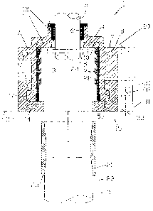
Referring to Figure 1, the top circulating head is designated by numeral 1,
and is used to couple a slick joint 2 with a bore hole casing 3.
The assembly 1 comprises a main body portion 4 having a large cylindrical
bore 5, a small cylindrical bore 6 and a flange portion 7 with a pair of
lifting lug holes 8, 9. Shoulder portion 10 between bores 5 and 6
supports a bumper ring 11 made of rubber or a similar material. Resilient
CA 02718929 2010-10-28
= ,.õ
WO 02/37015
PCT/NZ01/00227
12
(eg rubber) external seals 12 and 13 are mounted in the bores 5 and 6. A
locking assembly 15 is mounted on the body portion 4 about an
outwardly extending flange 14.
Referring to Figure 2, the locking assembly 15 has a first semicircular
door 16 and a second semicircular door 17. The doors 16,17 each have
respective hinge rings 30,31 (Figure 1) with bores 32,33 aligned with a
bore 20 in the flange 7. A pivot pin (not shown) passes through the
bores 20,32 and 33.
The main body portion 4 has'an outwardly extending flange 14 which is
received in an inwardly facing recess 51 formed in the doors 16,17. The
flange 14 has an upper locking surface 50 which engages a locking
surface 52 provided by the upper wall of the recess 51.
The casing 3 is screwed into a terminal collar 21. Prior to insertion of the
casing 3 and collar 21, the doors 16,17 (shown in their closed positions
in Figure 1) are pivoted to the open positions shown in Figure 2. This
permits the insertion of the terminal collar 21 into the bore 5.
Referring to Figures 3 and 4, when the terminal collar 21 has been fully
inserted against the bumper plate 11, the doors 16, 17 are pivoted to
their closed positions shown in Figures 3 and 4 and clamped together by
a lever clamp mechanism 22. The action of the mechanism 22 is shown
schematically in Figures 5a and 5b. The mechanism comprises a lever
arm 24 pivoted at one end to the door 16 and at the other end to a clip
25. As shown in Figure 5b, the clip 25 is hooked round a catch 26 on
the door and snapped shut as indicated by arrow 27 in Figure 5b. This
forces the doors 16,17 together and ensures a secure connection.
- Referring to Figure 3, in their closed positions the doors
16,17 engage a
shoulder 23 of terminal collar 21 so as to lock the casing 3 in place. The
terminal collar 21 also engages resilient external seal 13 so as to provide
CA 02718929 2010-10-28
. .
WO 02/37015
PCT/NZ01/00227
13
a fluid tight seal. The seal 13 has circumferential ribs 28,29 etc which
are angled in the direction of insertion of the casing 3. Similarly, the slick
joint 2 engages a resilient external seal 12 with reverse-directed ribs for a
fluid tight seal. The slick joint 2 has a support flange 24 which engages
the bumper ring 11 when the slick joint 2 is used to lift the casing 3 or to
lower the casing 3 into a borehole. Alternatively, the slick joint 2 can be
pushed downwards into the casing 3.
The seal 12 is mounted in the bore 6 between a pair of phosphor-bronze
bushes. The bushes and slick joint are highly polished in order to
minimise friction. A lubricant may also be provided.
The coupling apparatus 1 provides a fluid-tight seal between the slick joint
2 and casing 3, permitting fluid to be pumped at high pressure into the
casing 3. After the pumping operation is finished, the clamping
mechanism 22 is released and the doors 16,17 are pivoted to their open
positions. The assembly 1 is then lifted up by the slick joint 2 or by the
lug holes 8, 9.
Part of the weight of the casing 3 can be supported by the slick joint 2,
due to the secure connection provided by the substantially horizontal
locking surface 50 which supports.the opposed substantially horizontal
surface 52 of the doors 16,17. Although a horizontal locking surface 50
is provided on the flange 14, the surface 60 may have a positive or
negative camber. If a positive camber (le sloping to the outside) is
provided, then a stronger clamping mechanism 22 will be required to keep
the two members 16,17 together.
Although part of the weight of the casing can be supported by the slick
joint 2 as discussed above, the majority of the weight of the casing 3 is
supported by a side door elevator 49 which has a flange 48 with an upper
surface 47 which engages the bottom surfaces of the members 16,17.
CA 02718929 2010-10-28
..1.
WO 02/37015
PCT/NZ01/00227
14
The elevator 49 is coupled to a rig (not shown) in the manner shown in
detail in Figure 8.
The assembly 1 may be rotated with respect to the slick joint 2.
In an alternative arrangement the elevator 49 may be omitted and the
weight of the casing 3 transferred to a rig (not shown) by bails (also not
shown) attached to the lug holes 8,9. In this case the locking assembly
(which effectively functions as an elevator) may need to be reinforced
10 so as to support the weight of the casing 3 (which may be
many
hundreds of tons). Instead of transferring the weight via the lug holes
8,9, the assembly 15 may have lug holes or rings for attachment to the
bails.
15 An alternative assembly is shown schematically in Figure 6.
In this case
the locking assembly comprises a pair of members 40,41 which are
identical to the doors 16,17 in cross-section (apart from the omission of
the hinge rings 30,31). The members 40,41 are mounted on rams 42,43
which are driven by hydraulic cylinders 44,45 so as to translate the
members between the open position shown in Figure 6, and a closed
position (not shown).
In a further alternative shown schematically in Figure 7, the cylinders
44',45' are attached to member 41 and the rams 42',43' are attached to
the opposite member 40. It can be seen that the system of Figure 7 is
fully self contained, in the sense that no external mounting is required. In
contrast, in the system of Figure 6, the cylinders 44,45 must be mounted
on external supports.
A cross-section through an oil rig is shown in Figure 8. In an initial
drilling
operation the rig is used to drill a borehole with a drill pipe (not shown)
which is rotated by a top drive 50 or a rotary table 51. Following drilling,
a casing pipe 3 is passed along the length of the borehole.
CA 02718929 2010-10-28
=.;= .
WO 02/37015
PCT/NZ01/00227
Starting from the top of Figure 8, a set of suspension wires 55 are
coupled to a support structure (not shown). The wires 55 carry a block
. 56 with a hook 61 which support the top drive 50. The top drive 50 has
5 a drive shaft 59 and is prevented from rotating by a pair of
rails 62
mounted on a derrick (not shown).
A slick joint 2 is coupled to the drive shaft 59. A mud supply pipe 79 is
provided to pass mud at high pressure through the slick joint 2.
In contrast to Figure 3, the weight of the casing is supported by a slip
type elevator 63 (instead of a side door elevator) which has slips 64
which grip the sides of the casing 3. The slip type elevator 63 has a pair
of side lugs 46 which are supported by the bails 58. Thus the weight of
the casing 3 is transferred to the block 56 by the bails 58 via the elevator
63, bypassing the slick joint 2. Part of the weight of the casing 3 can
also be supported, if necessary, by the slick joint 2. The slick joint 2 is
coupled to the drive shaft 59 by a frangible coupling 60 incorporating
shear pins which break if the load carried by the slick joint 2 exceeds a
set threshold.
Various different types of top circulating head configuration are shown in
Figures 9-12. Components with a similar function are given the same
reference numerals as the equivalent components in Figures 1 and 3.
The bumper ring 11 shown in Figure 1 is replaced in Figures 9-12 with a
sliding piston-type bumper ring 65 with a flange 66 which slides up and
down the bore 5 sealed by resilient seals 67. The ring 65 is coupled to
the shoulder portion 10 and biased downwards by a coil spring 68.
In the embodiment of Figure 9, the ring 65 carries a resilient annulus of
material 70 on its lower face to form a top face seal which engages the
top of the collar 21.
= CA 02718929 2010-10-28
.
W002137015 PCT/NZ01/00227
16
When mud is pumped into the casing 3, mud at high pressure (up to 2500
psi) fills the chamber 90 defined by the upper.face of the bumper ring 65,
internal and upper faces of flange 66, bore 5 and shoulder 10. In
contrast, the chamber 71 below the ring 65 is free of mud. This sets up
a fluid pressure differential which forces the top face seal 70 against the
collar 21 and ensures a tight seal.
In an alternative arrangement shown in Figure 10, the top face seal is
replaced with an external seal formed by an annulus of resilient material
72 with a frustoconical inner surface 73 which provides a wedging action
when the bumper ring 65 forces the annulus 72 down into the chamber
71.
In a further alternative arrangement shown in Figure 11, the top face seal
is replaced with an internal seal formed by an annulus of resilient material
74 with a frustoconical outer surface 75 which engages the internal bore
76 of the collar 21 and provides a wedging action when the bumper ring
65 forces the annulus 74 down into the collar 21.
In a further alternative arrangement shown in Figure 12, the seal 13
(Figure 1) is replaced by a hydraulic seal, comprising a hollow torus of
rubber (or similar) material 80 with a toroidal chamber 81 which is
supplied with hydraulic fluid from a line 82. Anti extrusion rings 83,84
are provided to prevent the seal 80 from extruding up or down when
= inflated. The seal 80 engages the collar 21 and bore 5 when inflated.
This enables collars 21 with differing diameters to be accommodated.
Referring to Figure 13, an alternative top circulating head is shown,
comprising a body portion 90 with a seal 13 of the type described in
Figure 1. A casing tube 91 is received in the bore 5 of the body portion
90 and a seal is effected by the seal 13. A side door elevator 105 is
suspended from the bottom of the body portion 90 by a pair of chains 92,
= CA 02718929 2010-10-28
WO 02/37015
PCT/NZ01/00227
17
93. For purposes of clarity, the chains 92, 93 are showed in Figure 13
with only four links. However, in practice a larger number of links will be
required.
In contrast to the embodiments of Figures 1-12, the tubular shaft
extending down from the top drive 50 is rigidly connected (for example by
welding) to the body portion 90.
As shown in Figure 14, the elevator. 105 comprises a main body portion
94 attached to a door 95 via a hinge 96. The door 95 is locked in place
by a connector 97. The connector 97 can be released to permit the door
95 to swing back to the open position shown in dotted lines in Figure 14.
Prior to insertion of the casing 91, the elevator 105 (with door 95 in its
open position) is swung away from the mouth of the bore 5 on the chains
92, 93.
Once the casing 91 has been fully inserted into the bore 5, the elevator
105 is swung back and the casing 91 is received in the bore 98 of the
elevator. The door 95 is then swung back into place and locked by
connector 97. The casing 91 has a shoulder 99 which is engaged by the
elevator 105 to support the weight of the casing 91. The weight of the
casing 91 is transferred to a rig (not shown) via lugs 46 and bails (not
shown). This prevents the weight of the casing 91 being transferred
through the chains 92 and 93.
In the alternative embodiment of Figure 1 5, the side door elevator 105 of
Figure 13 is replaced with a slip type elevator. In this case, the body
portion of the top circulating head comprises a first portion 100 with a
bore 5, and a second, elevator portion 101 (formed as a single piece with
the portion 100, or attached eg by welding). Slips 102, in the form of up
to eight blades or wedges, are mounted inside elevator portion 101 and
are slid upwards into the bore 5 to permit the casing 103 to pass through
the elevator portion 101 into the bore 5. The slips may be lifted by a
. CA 02718929 2010-10-28
WO 02/37015
PCT/NZ01/00227
18
hand lever, pneumatic or hydraulic cylinder (not shown). The slips 102
then retract downwards as they take the weight of the casing 103.
It can be seen in Figure 15 that the use of a slip type elevator enables
casing 103 with no terminal collar to be supported. However, the slips
102 can be moved apart if necessary sufficiently to enable casing with a
terminal collar (such as the terminal collar 12 of Figure 1) to be inserted.
An alternative top circulating head assembly is shown in Figure 16. A top
drive connection 110 has an internally threaded bore 111 which receives
a top drive shaft (not shown). The internal bore 111 enables mud to be
pumped through the top drive connection 110. The top drive connection
110 has a pair of bores 112, 113 which receive shear bolts (not shown).
The bores 112, 113 are aligned with bores 114, 115 in a connector 116.
The shear bolts pass through the bores 114, 115 and provide a frangible
connection between the connector 116 and top drive connection 110.
The connector 116 has an internally threaded bore 117 which receives a
threaded end of a slick joint 118 to rigidly connect the slick joint 118 to
the connector 116. The connector 116 has a flange 120 which supports
an external saver sub assembly 121.
A bell designated generally at 122 is formed by a tube 123 which is
welded to a cap 124 and a flange 125. A keeper plate 127 is bolted to
the cap 124. The slick joint 118 engages a pair of phosphor-bronze
bearings 128, 129 and a seal 130, which enable the slick joint 118 to
slide up and down.
The slick joint 118 is attached at its lower end to a stinger adjustment
sub casing 131 which is attached in turn to a stinger 132 with a non drip
valve 133 at its lower end. The stinger is received inside casing 134 and
is maintained in a central position by an internal guide 135.
A coil spring 136 (shown in its compressed loaded configuration) is
CA 02718929 2010-10-28
,
WO 02/37015
PCT/NZ01/00227
19
mounted between cap 124 and a spring support flange 137 welded to the
slick joint 118.
The casing 134 has a terminal collar 138 which is clamped in place with a
locking assembly 139 similar to the locking assembly 15 shown in Figure
1.
A seal locking ring 141 and external seal 142 provide a fluid-tight seal
between the components.
The weight of the casing is supported as shown in Figure 8, that is by a
slip elevator 63 and pair of bails 58 (both omitted in Figure 16 for clarity).
The spring 136 allows a small movement between the slips 64 and the
casing 134, without the full weight of the casing being transferred
through the top circulating head to the connector 116, which would
cause the shear bolts to shear, resulting in down-time. Also, if an operator
tries to pick up the casing with the slips disengaged, then the spring 136
will compress further under this load as the slick joint 118 is pulled out of
the bell 122. The surface of the slick joint 118 is coated in a visible
colour (for example black or red) below the level where the slick joint 118
is normally visible. As the pull continues, more and more coloured slick
joint will appear, until the shear bolts shear. This colour change should
alert the operator that something is wrong.
The external saver sub assembly 121 is a hinged collar that fits onto the
flange of connector 116. When the casing 134 is lowered into a hole, it
may stick sufficiently to hold the entire weight of the casing. If the
operator is not monitoring the load indicator, and continues lowering the
top drive, then the slick joint 118 will slide down into the bell 122. As
this is happening, the slips 64 will release automatically and slide down
the casing.
At this point, the slick joint 118 will have slid all the way down into the
= CA 02718929 2010-10-28
WO 02/37015
PCT/NZ01/00227
bell until the external saver sub assembly 121 engages the keeper plate
127. Now if the operator lifts the top drive, the slips 64 will engage and
start lifting the casing 134.
5 It takes
about 50-70mm of downward movement to release the slips 64.
This is no longer possible because the external saver sub assembly 121 is
engaging the keeper plate 127. In order to release the slips, the external
saver sub assembly 121 is opened. This enables the top drive to be
lowered sufficiently to release the slips, and the slick joint to be pulled up
10 to its
operating position. The external saver sub assembly 121 can then
be closed. As an alternative, an internal saver sub assembly (comprising
an inflated torus 143) can be deflated to permit the terminal collar 138 to
move upwards inside the bell 122 sufficiently to release the slips.
15 A casing
drill-in system is shown in Figures 17-21. Casing 200 has a
drilling tool (not shown) mounted on its end. A suitable type of drilling
tool is described in W0/0146550. The system can lift, rotate and push
down on the casing 200 during a drilling operation. Lubricating mud can
also be directed under pressure down the casing 200 through the top
20 drive connection, as in the previously described embodiments.
Top drive connection 201 is coupled to a top drive 202. The top drive
connection 201 is welded directly to bell tube 203. The structure of the
= top circulating head is similar to the structure shown in Figure 16. The
casing is locked into the bell by a pair of doors 210,211 shown in their
open position in Figure 20. The doors 210,211 are clamped shut by a
clamp mechanism 212. Door 211 is mounted on a top hinge plate 213
and door 210 is mounted on a bottom hinge plate 214. For clarity, the
bottom hinge plate 214 is omitted from Figure 20. The hinge plates rotate
about a hinge pin 215 which is coupled to the bell 203 by a mounting
member 216. Each door 210,211 is formed with a number of gear teeth
205 which are received in recesses 206 formed in the bell flange 209, as
shown in the plan view of Figure 20.
CA 02718929 2010-10-28
WO 02/37015
PCT/11Z01/00227
21
The arms 210,211 each are connected to a respective jaw of a hypergrip
system 207 of the kind shown in detail In Figure 21. The connection is
made by approximately ten extended mounting bolts which each carry a
pair of springs, with the hypergrip system 207 mounted between the
springs. The system of Figure 21, and alternative gripping systems, are
described in detail in WO 01/21933. The system 207 has a pair of jaws
217,218 which are connected to respective hinge plates 219,220 which
rotate about the pivot pin 215. The jaws 217,218 are clamped in place by
a clamping mechanism 221.
Jaw 217 includes a semi-circular cage 315 containing rollers 316. Jaw
218 includes a semi-circular cage 317 containing rollers 318. The inner
faces of jaws 217 and 218 adjacent cage assemblies 315 and 317 have
recesses formed therein which have ramp surfaces for wedging the rollers
against the casing 200.
The jaws 217 and 218 may pivot away from each other so that the jaws
may open. This enables the casing 200 to be axially introduced between
the jaws and the jaws closed to retain the casing.
When cages 315 and 317 are in their initial positions, rollers 316 and 318
are positioned adjacent the apexes of the recesses formed in the jaws.
This allows the casing 200 to be rotated in either direction. When it is
desired to grip the casing 200, cages 315 and 317 are rotated relative to
jaws 217 and 218 in the direction .in which rotation is to be restrained.
This brings rollers 316 and 318 into engagement with their respective
ramp surfaces so as to wedge the rollers 316 and 318 between the outer
surface of casing 200 and jaws 217 and 218. To release casing 200 it
may be rotated in the opposite direction and locking mechanism 212 is
released to open the jaws.
CA 02718929 2010-10-28
WO 02/37015 PCT/NZ01/00227
22
The majority of the weight of the casing 200 is transferred to the top
drive 202 via the doors 210,211, bell flange 209, bell tube 203 and top
drive connection 201. Torque can also be transferred from the top drive
202 to the casing 200 via the same elements (including the gear teeth
205 and recesses 206).
The system of Figure 17 is intended to be used to drill relatively shallow
wells, thus restricting the string weight to a maximum of about 100 tons
(224,000 lbs). A circulating pressure of about 2500 psi is also envisaged.
Torque values in the range of 0-30,000 ft lbs are also envisaged.
The teeth 206 and recesses 206 can transmit torque up to approximately
30,000 ft lbs to the hypergrip system 207 via the mounting bolts. In the
event of an overload, the hinge pin 215 is able to carry the excess.
During drilling, mud is pumped down the casing and passes up the well on
the outside of the casing, bringing drilling cuttings up to the surface.
When a desired depth has been reached, cement is pumped down the -
inside of the casing. The cement may be pumped through the circulating
head shown in Figures 17-21, or using a different pump connection
apparatus. A plug is then driven down, which forces the cement up the
outside of the casing. The cement then dries and seals the casing in
place.
If further depth is required, then casing of = a smaller diameter can be
passed down inside the existing casing, with a smaller drill bit mounted
on its end. The drill-bit can then drill through the existing drill-bit and
the
=
process is repeated.
If the casing 200 is lifted while the hypergrip system 207 is transferring
torque, then the lower springs supporting the hypergrip system will
compress. Similarly, the upper springs will compress if a downward push
is made on the casing 200. This prevents the rollers 316,318 from taking
CA 02718929 2013-02-26
23
up axial load, which would cause deformation of the cages 315, 317
(which are designed to take up the weight of the rollers only).
It should be noted that the casing is engaged on its external surface by
the hypergrip system 207 and the top circulating head assembly. As a
result, if any of these components breaks up, parts will not fall down the
interior of the casing 200.
Also the hypergrip system 207 is actuated independently of the mud
circulation system.
Although this invention has been described by way of example and with
reference to possible embodiments thereof, it is to be understood that
modifications and improvements may be made without departing from the
scope of the invention.