Note: Descriptions are shown in the official language in which they were submitted.
PCT/CA2009/000377
CA 02719339 2010-09-21
WO 2009/117823
PCT/CA2009/000377
Continuous Measurement of Amine Loading in Gas Processing Plants
Using Raman Spectroscopy
Field of the Invention
The present invention relates to a system and method for continuous
measurement of
amine loading in gas processing plants using Raman spectroscopy.
Background
In its natural state, "raw" or "sour" natural gas contains acid gases such as
carbon dioxide
(CO2) and hydrogen sulphide (H2S). The process to produce pipeline quality
natural gas
requires the removal of these naturally occurring gases, typically through a
liquid absorption
process. Conventional acid gas absorbing liquids commonly used in the industry
include
amine-based solutions, or liquid amine.
The chemical reactions between the amine solution and the acid gas are
reversible,
allowing for thermal regeneration of the "rich" amine solution to remove the
CO2 and H2S.
The regenerated "lean" amine solution is then reused for another acid gas
absorption cycle.
The thermal regeneration of the "rich" amine solution is the single most
energy intensive step
during the acid gas removal process.
Gas processing plants do not currently have a means of continuously measuring
the acid
gas concentrations in the loaded (rich) and the regenerated (lean) absorbing
liquid. The acid
gas (CO2 and H2S) loading of the absorbing liquid during the process is
conventionally
determined manually by a plant operator based on lab titration. In most cases,
an excess
amount of energy is used to regenerate the absorbing liquid in order to meet
pipeline gas
PCT/CA2009/000377
CA 02719339 2010-09-21
WO 2009/117823
PCT/CA2009/000377
specifications. As a result, the absorbing liquid circulation rate and thermal
regeneration
temperatures are operated with a wide margin and are not optimized. The
ability to measure
the absorbing liquid acid concentration continuously, especially for the
regenerated lean
liquid, would be useful to the natural gas processing industry.
The inventors have identified that Raman spectroscopy can be used to measure
the acid
gas loading of the liquid absorption process. Raman spectroscopy is a
spectroscopic method
to study the chemical components in gas, liquid or solid state phases through
the vibration or
rotation of a molecule. Raman spectroscopy is commonly used to characterize
chemical
components by providing a fingerprint by which the molecule can be identified.
Typically, a
sample is illuminated with a light source in which the light is collected with
a lens and sent
through a monochromator. Wavelengths close to the laser line (due to elastic
Rayleigh
scattering) are filtered out and those in a certain spectral window away from
the laser line are
dispersed onto a detector. Spontaneous Raman scattering is typically very weak
and, as a
result, the main historical difficulty of employing Raman spectroscopy has
been separating the
weak inelastically scattered light from the intense Rayleigh scattered laser
light. A Raman
spectrometer consists of three main parts: a light source, a spectrograph and
a detector.
The inventors are not aware of any previous application of Raman spectroscopy
to the
measurement of acid gases in a basic solution, such as an amine solution used
in a gas
processing plant.
2
PCT/CA2009/000377
CA 02719339 2010-09-21
WO 2009/117823
PCT/CA2009/000377
Summary Of The Invention
The present invention relates to a system and method for continuous
measurement of
amine loading in gas processing plants using Raman spectroscopy.
In one aspect, the invention comprises a method of determining the
concentration of an
acid gas in a basic solution, comprising the steps of:
(a) providing a sample of the basic solution, and obtaining a Raman spectrum
having
characteristic peaks;
(b) comparing the sample Raman spectrum to a baseline or control Raman
spectrum and
determining a spectral change;
(c) correlating the spectral change with the acid gas concentration.
The basic solution may be an amine solution or an alkaline salt solution. The
spectral change
may comprise an increase or decrease in a peak height, or area under a peak,
or both. The
spectral change may occur at a peak of about 2574 cm-1. The spectral change
may comprise a
shift in a ratio of a first peak height or area to a second peak height or
area. The first peak and
second peak may be selected from the group consisting of:
First (cm-1) Second (cm-1)
300 1280
280 200
900 1000
400 1000
3
PCT/CA2009/000377
CA 02719339 2010-09-21
WO 2009/117823
PCT/CA2009/000377
In a second aspect, the invention may comprise a method of determining the
concentration
of an amine solution, comprising the steps of:
(a) providing a sample of the amine solution, and obtaining a Raman spectrum
having
characteristic peaks;
(b) comparing the sample Raman spectrum to a baseline or control Raman
spectrum and
determining a spectral change;
(c) correlating the spectral change with the amine concentration.
In a third aspect, the invention may comprise a method of optimizing basic
absorbent
solution regeneration in a gas processing plant, comprising the steps of:
(a) periodically sampling a lean stream basic solution or a rich stream basic
solution, or
both a lean stream and a rich stream;
(b) obtaining a Raman spectrum from one or both of a lean stream basic
solution or a
rich stream basic solution;
(c) comparing a spectral change in a measured Raman spectrum from a baseline
or
control Raman spectrum;
(d) correlating the spectral change with an acid gas concentration, or basic
solution
loading, or both; and
4
PCT/CA2009/000377
CA 02719339 2010-09-21
WO 2009/117823
PCT/CA2009/000377
(e) if necessary, varying a regeneration parameter in response to the acid gas
concentration or basic solution loading, or both.
The regeneration parameter may comprise an amine addition rate, or a heat
addition rate.
In yet another aspect, the invention may comprise a system for optimizing
basic absorbent
solution regeneration in a gas processing plant, said system comprising:
(a) a sampler for periodically obtaining a sample of one or both of a lean
stream basic
solution or a rich stream basic solution;
(b) a Raman spectrometer to obtain a Raman spectrum from one or both of a lean
stream
basic solution or a rich stream basic solution;
(c) at least one memory, the memory containing a set of program instructions
and at least
one baseline or control Raman spectrum;
(d) at least one processor operatively connected to the memory, the at least
one processor
responsive to the program instructions to:
(i) compare a spectral change in the measured Raman spectrum from the baseline
or
control Raman spectrum;
(ii) correlate the spectral change with an acid gas concentration, or basic
solution
loading, or both; and
5
PCT/CA2009/000377
CA 02719339 2010-09-21
WO 2009/117823
PCT/CA2009/000377
(iii) determine if a change to a regeneration parameter is necessary, and if
so, provide
control information to implement the change.
In one embodiment, the system further includes an actuator, responsive to the
control
information, to change the regeneration parameter.
Brief Description Of The Drawings
The invention will now be described in relation to the drawings in which:
Figure 1 is a schematic diagram of a conventional liquid amine absorption
process.
Figure 2 is a schematic diagram of a Raman spectrometer.
Figure 3 shows MDEA Raman spectra for varying CO2 sparging times.
Figure 4 is a graph showing the Raman peak ratio of ionized MDEA/free MDEA
versus
CO2 concentration.
Figure 5 is a graph showing hydrogen carbonate peak intensity versus CO2
concentration
in MDEA.
Figure 6 is a graph showing the Raman peak ratio of ionized DEA/free DEA
versus CO2
concentration.
Figure 7 is a graph showing hydrogen carbonate peak intensity versus CO2
concentration
in DEA.
6
PCT/CA2009/000377
CA 02719339 2010-09-21
WO 2009/117823
PCT/CA2009/000377
Figure 8 is a graph showing the Raman peak ratio of ionized MEA/free MEA
versus CO2
concentration.
Figure 9 is a graph showing the hydrogen carbonate peak intensity versus CO2
concentration in MEA.
Figure 10 is a graph showing MEA 300/1280 relative peak intensity correlation
to CO2
loading.
Figure 11 is a graph showing DEA 280/200 relative peak intensity correlation
to CO2
loading.
Figure 12 is a graph showing MDEA 400/1000 relative peak intensity correlation
to CO2
loading.
Figure 13 is a graph showing DGA 900/1000 relative peak intensity correlation
to CO2
loading.
Figure 14 shows the Raman spectrum of the DEA loaded with H2S.
Figure 15 is a graph showing the correlation of Raman peak at 2574 cm-1 and
H2S
concentration.
Figure 16 is a schematic diagram of the simulated continuous measurement test
set up.
Figures 17A and 17B are schematic diagrams of the set up for H2S and CO2
concentration
calibration of rich amine stream at high pressure conditions.
Figure 18 shows the Raman spectra from the simulated continuous measurement.
7
PCT/CA2009/000377
CA 02719339 2010-09-21
WO 2009/117823
PCT/CA2009/000377
Figure 19 is a schematic diagram of the Raman analyzer sampling location in
the gas
plant.
Figure 20 is a schematic diagram of the Raman analyzer interface to plant
process.
Figure 21 is a design drawing of the sampling interface.
Figure 22 shows a typical Raman spectra of pure MDEA, lean and rich amine
solutions.
Figure 23 is a graph showing Raman peak area versus time of four Raman peaks
at 2969,
2906, 2825 and 2574 cm-1 from rich probe.
Figure 24 is a graph showing a normalized Raman peak area of 2574 cm-1 peak
using
Raman peak at 2969 cm-I as the reference peak.
Figure 25 is a graph showing the comparison of the calculated H2S removal rate
(kg/hr)
and the Raman peak ratio of 2574/2969 from rich probe (Black line ¨ calculated
H2S removal
rate from the plant process data; Gray line ¨Raman peak ratio of 2574/2969).
Figure 26 is a graph showing the comparison of the calculated CO2 removal rate
(kg/hr)
and the Raman peak ratio from rich probe (Black line ¨ calculated CO2 removal
rate from the
plant process; gray line ¨ CO2 loading related to Raman peak ratio).
Figure 27 is a graph showing the neural network prediction model test results
for H2S
removal.
Figure 28 is a graph showing the neural network prediction model test results
for CO2
removal.
8
CA 02719339 2016-04-26
Figure 29 shows the Raman spectra of MDEA solutions with different
concentration.
Figure 30 is a graph showing the MDEA concentration vs. the Raman peak
intensity ratio
1467(mDEA)/1640( water).
Figure 31 is a graph showing the correlation of pH value and the MDEA solution
concentration.
Figure 32 shows the Raman spectra of carbonate and bicarbonate.
Figures 33A-E are correlation graphs of Raman peak ratios to acid gas loading.
Figures 34A-C are correlation graphs of Raman peak ratios to amine
concentration.
Detailed Description Of Preferred Embodiments
When describing the present invention, all terms not defined herein have their
common
art-recognized meanings.
To the extent that the following description is of a specific embodiment or a
particular
use of the invention, it is intended to be illustrative only, and not limiting
of the claimed
invention. The scope of the claims should not be limited by the embodiments
set forth in the
examples, but should be give the broadest interpretation consistent with the
description as a
whole.
The term "about" shall mean a range of values within plus/minus 10% of the
stated value,
or within the acceptable error range of methods or apparatuses used to measure
the stated value.
In particular, with respect to the peak shift of a Raman spectrograph, the
term "about"
9
PCT/CA2009/000377
CA 02719339 2010-09-21
WO 2009/117823
PCT/CA2009/000377
indicates the inclusion of a peak value which differs slightly from the stated
value because of
differences in standardization, calibration or other factors unique to the
measurement method
or spectrometer.
Acid gases such as CO2 and H2S and must be removed from a natural gas stream
before its
commercial sale. A liquid absorption process is commonly used for acid gas
removal. The
absorbing liquid chemically reacts with acid gases in an absorption cycle to
produce a clean
natural gas stream. The dirty absorbing liquid can be reused after a
regeneration cycle, which
cleans up the absorbing liquid.
In one aspect, the present invention comprises the use of Raman spectroscopy
for online
measurement of the chemical reaction and change in chemical components during
acid gas
absorption and regeneration. The inventors have developed a system and method
using
Raman spectroscopy to achieve continuous measurements of acid gas loading of
absorbing
solutions in liquid absorption processes commonly used in natural gas
sweetening processes,
such as aqueous amine based liquid absorption process. The most common acid
gas
components include H2S and CO2. Possible other acid gas components can be
measured
simultaneously from the multi-streams; for example, the rich and lean amine
acid loading can
be measured at the same time. Using Raman spectroscopy to measure continuously
CO2 and
H2S loading in the absorbing liquids from both absorption and regeneration
cycle is not
known in the gas processing industry. In addition, other unwanted chemicals
produced during
the processes can also be measured, such as heat stable salts and the
chemicals from amine
PCT/CA2009/000377
CA 02719339 2010-09-21
WO 2009/117823
PCT/CA2009/000377
degradation and oxidation. The continuous online measurement can provide more
frequent
and accurate information for optimizing the process in gas processing plants.
Exemplary embodiments of the system and method of the present invention are
described
in the Examples, where laboratory measurements were obtained of some simulated
samples
using a process Raman spectrometer. These simulated samples comprise most
commonly
used absorbing solutions including monoethanolamine (MEA), diethanolamine
(DEA),
methyl diethanolamine (MDEA), diglycolamine (DGA), triethanolamine (TEA).
diisopropanolamine (DIPA) and an inorganic based absorbing solution such as
alkaline salt
solutions, for example, potassium carbonate, sodium carbonate, sodium
hydroxide, or
potassium hydroxide. Other mixed amine/sulphur-based absorbing solutions, such
as those
involved in the SulfinolTM process, can also be used. The inventors have found
that Raman
based spectroscopic measurement system and method may serve as a useful
process control
tool for gas processing plants.
As used herein, the term "basic solution" comprises a solution of an amine or
an alkaline
salt, including those absorbing solutions commonly used or known to absorb
acid gases.
In current plant operations, utilizing amine absorption, amine circulation
rates are
determined through a manual measuring process with an approximate 12 hour
frequency. In
most cases, an excess amount of energy, typically 20-30% more steam than
necessary is used
to regenerate the amine as a safeguard in order to meet pipeline gas
specifications.
By utilizing the Raman spectroscopic based process monitoring system and
method, which
includes an interface to the gas process stream, continuous measurements of
the acid loading
11
PCT/CA2009/000377
CA 02719339 2010-09-21
WO 2009/117823
PCT/CA2009/000377
(including both H2S and CO2) from both rich amine and lean amine streams can
be conducted
simultaneously. The direct measurement of total acid loading in the rich and
lean amine
streams provide the process guide for the amine circulation rate and the steam
(heat) flow rate
for the regeneration cycle. Both amine circulation rate and steam flow rate
are important and
economically significant parameters. By optimizing one or both, significant
cost savings may
be achieved.
The Raman-based instrumentation system and method of the present invention may
extend
to other liquid absorption processes using other types of liquid absorbent
basic solutions, such
as alkaline salt solutions, for example, potassium carbonate, sodium
carbonate, sodium
hydroxide, potassium hydroxide solutions. In one embodiment, the system
provides
continuous measurement with result feedback to the process control, which
preferably occurs
in real-time. The system may be integrated into existing process streams.
Raman spectroscopy is a spectroscopic technique used in condensed matter
physics and
chemistry to study vibrational, rotational, and other low-frequency modes in a
system. It relies
on inelastic scattering, or Raman scattering of monochromatic light, usually
from a laser in the
visible, near infrared, or near ultraviolet range. The laser light interacts
with phonons or other
excitations in the system, resulting in the energy of the laser photons being
shifted up or
down. The shift in energy gives information about the phonon modes in the
system. The basic
principles of Raman spectroscopy as a general technique are well known in the
art, and may
be reviewed in Gardiner, D.J. (1989) Practical Raman spectroscopy, Springer-
Verlag, ISBN
12
CA 02719339 2016-04-26
978-0387502540, where permitted.
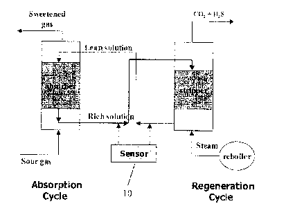
In one embodiment, a system of the present invention maybe integrated into an
existing
gas process stream, as schematically shown in Figure 1. The sensor (10) may
read one or both of
the rich solution or the lean solution. In a preferred embodiment, multiple
sampling of both the
rich and lean solutions may take place. A multiple sampling analysis point is
a set-up on a
Raman spectrometer that could have multiple probes connected to the
spectrometer and measure
multiple streams from a process, such as, measuring the lean stream and the
rich stream using
one spectrometer.
As shown in Figure 2, in one embodiment, the system comprises a light source
(12)
which passes through the sample (14) and which is then read in the
spectrograph (16). The
scattered light then passes to the detector (18) which reads the shifts in
light energy, and passes
that data onto a processor (20), which may be a general purpose computer
running suitable
software.
The information from a Raman spectrum is directly related to the chemical
components
in a liquid sample. Each different component will have a different functional
group and will
exhibit a different Raman spectrum. Different amines have their own
characteristic Raman
peaks. The intensity of each diagnostic Raman peak can be used to measure the
concentration of
the species in the solution. When the amine reacts with the CO2 or H2S, the
Raman spectrum
will be changed. The spectral change can be categorized as: 1) the spectral
change
13
PCT/CA2009/000377
CA 02719339 2010-09-21
WO 2009/117823 PCT/CA2009/000377
of the amine itself, and 2) a spectral change related to the newly formed
species. These
spectral changes can then be used to measure the acid gas loading in the
liquid amine phase.
The basic acid gas absorption reactions can be expressed using the following
equations:
RNH2 + CO2 + H20 RNH3+ + HCO3-
2RNH2 + CO2 RNH3+ + RNHCO2- (reaction with CO2)
RNH2 + HCO3- RNH3+ + CO3
RNH2+ H2S RNH3+ + HS- (reaction with H2S)
The free amine RNH2 reacts with CO2 or H2S to form ionized amine (RNH3+),
carbamate
(RNHCO2-), hydrogen carbonate (HCO3-), carbonate (C032-) and HS-. These
species have
their own characteristic Raman peaks. The peak intensity also varies when the
concentration
of each species changes. By measuring these changes provided by Raman spectra,
the
concentration of CO2 and H2S in rich amine and lean amine solutions can be
measured.
In one embodiment, peaks corresponding to ionized amine and free amine provide
useful
information. The inventors have found that the ratio of ionized amine to free
amine correlates
strongly to CO2 concentration, as shown in Figures 4 and 6, and hydrogen
carbonate
concentration also correlates strongly to CO2 concentration, as shown in
Figure 5 and 7. In
one embodiment, CO2 concentration is measured as the molar ratio of CO2 to
amine.
In another embodiment, relative peak intensities may also be measured. The
inventors
have determined that the ratio of peaks of the Raman spectra is also
indicative of acid gas
concentration. For example, the ratio of peaks of about 300 cm-1 and 1280 cm-1
(within
14
PCT/CA2009/000377
CA 02719339 2010-09-21
WO 2009/117823 PCT/CA2009/000377
5cm-1 of these values) strongly correlates to CO2 concentration in an MEA
solution. Other
useful peak ratios for different amines are provided below:
MEA 300 cm-1 /1280 cm-1
DEA 280 cm-1 /200 cm-1
MDEA 900 cm-1 /1000 cm-1
DGA 400 cm-1 /1000 cm-1
The typical Raman spectrum of DEA loaded with H2S is shown in Figure 14. The
inventors have determined that the peak at 2574 cm-1 is related to the
concentration of the H2S
in the amine solution. Based on the peak area or intensity at 2574 cm-1, the
concentration
loaded in the sample can be correlated with empirical chemical analysis
results. In the
alternative, or additionally, a ratio of the peak at 2574 cm-1 to a baseline
or normalized peak
may be correlated with H2S concentration.
Elements of the present invention can be realized in hardware, software, or a
combination
of hardware and software. A typical combination of hardware and software could
be a general
purpose computer system or other data processing system with a computer
program that, when
being loaded and executed, controls the computer system such that it carries
out the methods
described herein. Prop-am instructions includes any expression, in any
language, code or
notation, of a set of instructions intended to cause a data processing system
having an
information processing capability to perform a particular function either
directly or after
conversion to another language, code or notation, and/or reproduction in a
different material
form.
PCT/CA2009/000377
CA 02719339 2010-09-21
WO 2009/117823 PCT/CA2009/000377
In one embodiment, the invention comprises a system for optimizing basic
absorbent
solution regeneration in a gas processing plant. Automatic or manual samplers
are provided
on each of the rich and lean amine streams, which are connected to a Raman
spectroscopy
system. The general configuration of such a system is schematically
illustrated in Figures 19
and 20. The sampler may comprise a flow-through cell.
The system is conveniently implemented with a general purpose computer
including
conventional memory and a processor. The memory may contain a set of program
instructions and at least one baseline or control Raman spectrum. The
processor is responsive
to program instructions which are coded to implement the method steps
described herein.
In one embodiment, the program instructions cause the processor to (i) compare
a spectral
change in the measured Raman spectrum from the baseline or control Raman
spectrum, (ii)
correlate the spectral change with an acid gas concentration, or basic
solution loading, or both,
and determine if a change to a regeneration parameter is necessary, and if so,
provide control
information to implement the change.
The control information is then used to control at least one actuator to
change the
regeneration parameter. The actuator may be used to increase or decrease amine
addition to
the regeneration fluid, or the actuator may be used to increase or decrease
the heat supplied in
the regeneration process.
16
PCT/CA2009/000377
CA 02719339 2010-09-21
WO 2009/117823
PCT/CA2009/000377
The present invention is described in the following Examples, which are set
forth to aid in
the understanding of the invention, and should not be construed to limit in
any way the scope
of the invention as defined in the claims which follow thereafter.
EXAMPLES
EXAMPLE 1 ¨ CO2 LOADING TESTS
This example involves the comparison of a chemical analysis method and a Raman
spectroscopy measurement of the same sample generated from the absorption
reaction of CO2.
Generation of amine samples with different CO2 concentrations
To gather amine samples with varying concentrations of CO2, a steady 0.18 Lpm
stream of
15% CO2 balanced with N2 gas was bubbled through a ceramic sparger immersed in
the amine
solution. Samples of approximately 30 mL were then removed from the amine at
specific
time intervals, with a portion of each sample run through the Raman
spectroscope and another
portion being sent for titration. Samples with CO2 sparging times between 10
minutes and 6
hours were taken to gather data for a wide range of CO2 concentrations.
CO2 concentration analysis from titration
Titration was performed in accordance with UOP Method 829-82: Titrimetric
Determination of CO2 in Ethanolamines. This method prescribes a dilution of
the amine
sample in a standard volume of >99.8% purity methanol and to use sodium
hydroxide (NaOH)
17
PCT/CA2009/000377
CA 02719339 2010-09-21
WO 2009/117823 PCT/CA2009/000377
as the titrant. Thymolpthaelin indicates when the titration is complete.
Calculation of the
CO2 loading condition of the amine is performed according to the formula:
c¨ 3.2(A ¨B)M
V
Where,
C, is the CO2 concentration in the amine sample [scf CO2/gallon amine]
A, is the volume of titrant needed for the amine sample [mL]
B, is the volume of titrant needed for the blank methanol solution [mL]
M, is the molarity of the NaOH solution [mol/L]
V, is the volume of amine sample used in the titration [mL]
Spectroscopic measurement of the CO2 loading in different amines
Raman spectra of each acid gas loaded amine sample were collected from a
ChromexTM
R2000 Spectrometer. A diode laser with 785 nm line and 125 mW power was used
as the
excitation source of the spectrometer. An ANDORTM TE cooled CCD camera was
used as the
detector. The integration time of each spectrum was 30 seconds.
The Raman spectra of four different amine solutions (MEA, DEA, DGA and MDEA)
with
different CO2 loading, were collected and spectral analysis of these spectra
was conducted.
Typical Raman spectra of pure MDEA and MDEA loaded with CO2 are shown in
Figure
3. Comparing this set of spectra, it may be seen that there are significant
spectral differences
from the solutions of pure "unloaded" MDEA and the CO2 loaded MDEA. These
spectral
differences can be used to label the amount of CO2 in the amine solution.
After initial tests determined approximate loading conditions for a wide range
of time
intervals, the range was narrowed to include only those time intervals and
concentrations
18
PCT/CA2009/000377
CA 02719339 2010-09-21
WO 2009/117823 PCT/CA2009/000377
wherein lean solution loading was normally experienced in gas processing plant
operations
[Engineering Data Book, Gas Processors Suppliers Association Vol. II, Sec.
21]. The ranges
for each of the amine solutions are shown in Table 1:
Table 1: Amine Loading Ranges and Corresponding Sparging Times
Amine Normal Range Corresponding Revised Sampling
¨Lean Loading Sparging Time Experiment
Period
(mol CO2/mol (minutes) Range (minutes)
amine) (minutes)
MEA 0.12 90 60-120 5
DEA 0.08 45 20-60 2
DGA 0.10 150 100-200 10
MDEA 0.005-0.01 ¨9 4-9 1
Species Spectral Analysis
The use of a Raman spectra measurement used to determine the CO2 loading in an
amine
solution was demonstrated by correlating peak intensity to CO2 concentration
obtained from
the titration method.
The Raman peak assignments of three commonly used amines were given in Table
2.
Table 2: Raman band assignment of amines before and after acid gas absorption
reaction
Raman peak cm-1
MDEA DEA MEA
Species
Ionized amine (RNH3 ) 745 787 867
Free amine (RNH2) 792 820 839
Carbamates (RNHCO2-) 505 572 550
Free amine (RNH2) 1465 1470 1467
Hydrogen carbonate (HCO3-) 1020 1020 1020
Carbonate (C032-) 1072 1072 1072
19
PCT/CA2009/000377
CA 02719339 2010-09-21
WO 2009/117823 PCT/CA2009/000377
The correlation of CO2 concentration and typical Raman peak measurements of
MDEA
are provided in Figure 4 and 5. As may be seen, there are close correlations
between the ratio
of ionized amine to free amine and Raman peak intensity of hydrogen carbonate
and
concentration of loaded CO2..
The correlation of CO2 concentration and typical Raman peak measurements of
DEA and
MEA are provided in Figures 6-9, where similar correlations may be seen.
Empirical Spectral Analysis
Table 3 shows the major peak relations for each of the samples investigated,
and the
correlation coefficient corresponding to the most linear peak ratios. Peaks
entitled for
example, "300" or "1280" peak, do not necessarily occur at exactly 300 cm-I or
1280 cm-I, but
are within + 5 cm-1 of these values, and are thus titled for the sake of
simplicity.
Figures 10-13 graphically illustrate the results from Table 3, and show the
specific data
points used to obtain the correlation coefficients shown.
Table 3: Amine Correlations Using Spectral Peak Ratios
Range Tested Peak Ratio Correlation
(mol CO2/mol Used for Coefficient
Amine Concentration amine) Correlation (R2)
MEA 19.4% 0.06-0.26 300/1280 0.98
DEA 21.0% 0.02-0.14 280/200 0.89
DGA 21.0% 0-0.4 900/1000 0.92
MDEA 40.0% 0-0.3* 400/1000 0.999
*This range was used due to control restraints on taking several samples
between the low and narrow range of
0.005 and 0.01 mol CO2/mol amine, or between 4 and 9 minutes of CO2 sparging
time.
PCT/CA2009/000377
CA 02719339 2010-09-21
WO 2009/117823 PCT/CA2009/000377
EXAMPLE 2¨ H2S LOADING TESTS
This example involves the comparison of a chemical analysis method and a Raman
spectroscopy measurement of the same sample generated from the absorption
reaction of H2S.
Absorption reaction experiment
This experiment produced sample solutions with different concentrations of H2S
absorbed
in different aqueous amine solutions. The lab samples were generated by
bubbling a gas
stream of 2% H2S balanced with N2 into an aqueous amine solution containing
¨40% (v/v) of
amine and ¨ 60% (v/v) of water. The aqueous amine solution, which has the pH
value
¨12.70, absorbs the H2S into the amine solution. The off-gas, which is not
absorbed by amine
solution, is vented into a contained vent system for flaring at the certified
H2S handling
facility.
Samples of approximately 20 mL were then collected from the H2S loaded amine
solution
into closed sample containers for chemical and instrument analysis. The sample
generation,
chemical analysis, and Raman spectra analysis were conducted in the certified
H2S handling
facility at the Alberta Research Council (Edmonton, Canada).
Chemical analysis of H25 loading in the amine solution used the standard UOP
Method
827-81. This method (providing control) and a precision method are used for
determination
of apparent hydrogen sulphide in amine solutions. Hydrogen sulphide is
determined by
21
PCT/CA2009/000377
CA 02719339 2010-09-21
WO 2009/117823 PCT/CA2009/000377
oxidation with standard iodine solution in an acid medium. HC1 is provided as
the acidic
medium. The chemical reaction is as follows:
H2S + 12 (excess amount) ==== S + 2H1+ 12
According to the method, the amount of sample to be taken for analysis was
determined
from the following table and the precision method was selected for the sample
analysis:
Apparent H2S concentration expected in Sample Size
the sample (grains/gallon) mL
>100 1.0
<100 5.0,10.0
Sample chemical analysis calculations
The concentration of apparent hydrogen sulphide in the sample solution was
calculated as
follows:
Apparent H2S, gain/gallon = 1991(A x M1 ¨ 0.5B x M2)/'V
Where,
B, is the standard sodium thiosulfate solution [mL],
M2, is the molarity of the sodium thiosulfate solution [mol/L]
A, is the volume of titrant needed for the amine sample [mL]
MI, is the molarity of the NaOH solution [mol/L]
V, is the volume of amine sample used in the titration [mL]
The apparent hydrogen sulphide concentration in grains/gallon may be converted
to
volumes of hydrogen sulphide, as a dry gas at 15.6 C (60 FO) and 101.3 kPa
(760mm) to
volume of solution by dividing by 84.
The apparent hydrogen sulphide concentration my be converted to wt-ppm as
follows:
Apparent H2S, wt-ppm = 17 x C/S
22
PCT/CA2009/000377
CA 02719339 2010-09-21
WO 2009/117823 PCT/CA2009/000377
Where,
C, is the apparent H2S content, grain/gallon
S, is the specific gravity of sample, 60/60 F (15.6/15.6 C)
The volume of standard iodine solution is varied with the hydrogen sulphide
content of the
amine solution sample. Sufficient iodine solution is taken so that about 10 mL
of standard
sodium thiosulfate solution are required for back titration. When the amine
sample solution is
concentrated and viscous, it is preferable to pipette the sample into an
Erlenmeyer flask
containing 50 mL of water. The pipette is rinsed with water into the flask.
The diluted
sample is then mixed with the acidified iodine solution. This procedure
prevents the local
neutralization of the iodine by strong amine solution. Since free amine reacts
quite rapidly
with iodine solution, the amine solution should contact iodine only in the
presence of excess
acid.
Raman spectroscopic measurement and results compared to the chemical analysis
Two sets of tests were conducted with two different types of Raman
spectrometers. The
first set demonstrates Raman measurement of H2S loading using the ChromexTM
R2000 bench
top Raman spectrometer. The amine solutions used in the first set were aqueous
DEA and
MDEA solutions. The samples loaded with different H2S concentration were
collected and
the Raman measurements and chemical analysis were conducted. The Raman spectra
of each
sample were acquired under following instrument conditions: 1) 785 nm was the
laser line. 2)
The power of the laser was 100 mW. 3) The integration time for each sample was
2 minutes.
4) The spectral range was from 100 to 3400 cm-1.
23
PCT/CA2009/000377
CA 02719339 2010-09-21
WO 2009/117823
PCT/CA2009/000377
The typical Raman spectrum of the DEA loaded with H2S is shown in Figure 14.
The
peak at 2574 cm-1 is the signature peak of H2S in DEA. The intensity of this
peak is related to
the concentration of the H2S in the amine solution. Based on the peak area or
intensity at
2574 cm-1, the concentration loaded in the sample can be correlated with the
chemical analysis
results.
Many other spectral changes occurred during the chemical reaction between
amine and
H2S. These spectral changes could also be used to help quantify H2S load.
Further details of
spectral analysis are provided in Example 3.
The Raman spectra of MDEA with different H2S concentrations were collected and
compared with the H2S concentration chemical analysis. The results were
plotted as the
correlation of the Raman H2S peak intensity (at 2606 cm-1) and the H2S
concentration (Figure
15).
A second set of Raman tests was conducted using the Bruker SentinelTM R100
process
Raman spectrometer and a custom made flow cell which was connected to the
sample
generation apparatus and simulated continuous measurement. The schematic
diagram of the
test set-up is shown in Figure 16. A mixture of 750 mL 40% (v/v) MDE and 60%
(v/v) water
was filled in the sample generation chamber as the absorbing liquid. The
liquid was pumped
into the Raman flow cell and flowed back to the liquid chamber. The Raman
spectrum was
collected every 20 minutes through the Raman probe which is inserted into the
flow cell while
the 2% H2S gas flowed through the absorbing liquid. The test ran continuously
for 4 days.
The Raman spectra of the MDEA solution with different H2S loading were
collected. The
24
PCT/CA2009/000377
CA 02719339 2010-09-21
WO 2009/117823 PCT/CA2009/000377
chemical analysis was conducted of the sample solution at the end of the test.
The resulting
spectra of this set of tests were plotted (Figure 18). The dot line is the
Raman spectrum
obtained after just 10 minutes showing low levels of CO2 or H2S. The solid
line in Figure 18
is the Raman spectrum after 20 hours.
EXAMPLE 3¨ FIELD TRIAL AND RESULTS
A field trial was conducted in a natural gas processing plant in Alberta. Two
sample ports
were connected to a measurement system of the present invention, as shown
schematically in
Figures 19 and 20. One port was from the rich amine stream after the heat
exchange, before
the stream entered the regeneration cycle. The second port is from the lean
amine stream
come out from the reboiler and after the heat exchange. The major components
of
measurement interface including the filtration system, flow cells, Raman
probes and flow
meter were enclosed in a box. The design of the sampling interface used is
shown in Figure
21. Figure 21 gives the sampling interface including probe, flow cell and the
three stage
sample filtration system Between the interface and the Raman spectrometer, a
200 meter
optic fibre cable was installed for optical signal transfer. The Raman signal
of the sample
flowing through the flow cell was collected by the optical probes and sent
back to the
spectrometer through the optical fibre cable. The Raman spectrometer
controlled two probes
and collected spectral data from the two probes every 20 minutes.
PC software was installed on the process Raman spectrometer computer. The on-
line
Raman measurement data was downloaded from the instrument computer to a remote
location.
PCT/CA2009/000377
CA 02719339 2010-09-21
WO 2009/117823 PCT/CA2009/000377
A five month period plant on-line measurement was conducted using the
described set-up.
The on-line Raman data were collected from both the rich and lean process
streams. Typical
Raman spectra of pure MDEA, lean and rich amine are shown in Figure 22.
To be able to evaluate the on-line measurements, a comparison between the
Raman
measurements and the related plant process data is an important initial step.
The key process
data related to H2S loading, CO2 loading and other data which indicated the
process variation
were provided by the gas plant. The collected on-line Raman data were
processed using the
following steps:
a) Convert original data file into XY data column (X: Raman shift with peak
position, Y:
Peak intensity).
b) Identify spectral component which related to the variation of the amine
stream acid
loading, including CO2 and H2S loading, and the amine strength.
c) Conduct each signature peak calculation, on peak intensity or peak area
(using suitable
Spectrum Analysis UtilitiesTM software).
d) Plot the signature peak area against the time stamps results in the on-line
raw data
graphs.
e) Select one Raman peak for use as a reference peak ratio to the rest of the
Raman peaks
and generate the normalized on-line Raman results.
A plot of Raman peak area versus time of four Raman peaks at 2969, 2906, 2825
and 2574
cm-1 from rich probe is shown in Figure 23. Figure 24 is the plot of
normalized Raman peak
26
PCT/CA2009/000377
CA 02719339 2010-09-21
WO 2009/117823 PCT/CA2009/000377
area of 2574 cm-I peak, using Raman peak at 2969 cm-1 as the reference peak,
versus time.
The amine peak at 2969 cm-1 was used as a reference due to its large peak area
and low signal-
to-noise ratio although any of the amine peaks can be used as reference.
The H2S and CO2 removal rate from the gas plant process is calculated based on
the
differences of H2S and CO2 levels in feed gas stream and the cleaned gas
stream as follows:
H2S removal rate (kg/hr) = Mass rate x (H2Sin ¨ H2Sout)/1000000
Mass rate = calculated from absorber data
H2Sin = H2S level in combined inlet gas, ppm
H2Sout = H2S level in sweet gas from absorber, ppm
CO2 removal rate (kg/hr) = Mass rate x (CO2in ¨ CO2out)/1000000
CO2in = CO2 level in combined inlet gas, ppm
CO2out = CO2 level in sweet sales gas, ppm
The Raman peak at 2574 cm-1 is characterized as the vsH. This peak should
strongly relate
to H2S loading in amine solution according to the overall basic chemical
reaction:
R3N + 2H20 + H2S(g) + CO2 (g) --- R3NH+ + SH- + 2H+ + 2HCO3-
The comparisons of the calculated H2S and CO2 removal rates from the plant
process and
the related Raman peak ratios are shown in Figures 25 and 26.
In Figure 25, the black line is the calculated H2S removal rate from the plant
process data
and the grey line is the Raman peak ratio of 2574/2969 cm* This peak ratio is
strongly
related to the H2S loading in amine solution, since the 2574 cm-1 is the
characteristic peak of
the SW in solution phase. Overall, the Raman data follows the plant process
data, although
27
PCT/CA2009/000377
CA 02719339 2010-09-21
WO 2009/117823 PCT/CA2009/000377
there are also some periods that the Raman data is off the scale. A similar
situation is shown
in Figure 26 for CO2 comparison, in which a few Raman peak ratios were used as
they
relatively related to CO2 loading in solution phase. The comparison results
indicate that the
Raman measurements overall follow the H2S and CO2 removal variation of the
plant process.
It shows that Raman spectral measurement provides strong indications of the
acid gas loading
including H2S and CO2 in amine solution in a continuous and non-invasive
manner.
In a Raman spectrum for the spectral range of 3000 cm-I to 200 cm-1, 18 Raman
peaks in
total were identified which related to H2S and CO2 loading in amine solution
and also related
to amine strength, i.e., the amine concentration in aqueous solution. The peak
at
2969 cm-I was used as a reference peak and other peaks were normalized by
ratio to peak
2969 cm-I.
Principal Component Analysis (PCA) was conducted on all 17 normalized spectral
peaks.
For H2S removal, top three ranked components and the percentage of variation
they explain in
the data sets are provided in Table 4. The most influential inputs in each
component are
shaded. Two data sets were created with the three components as inputs and the
process data
from gas plant as output. The data sets inputs and outputs are listed in
Table 5.
28
PCT/CA2009/000377
CA 02719339 2010-09-21
WO 2009/117823 PCT/CA2009/000377
Table 4: Principal Component Analysis for H2S removal
Cumm % 51.93% 77.34% 90.67%
Percent explained 51.93% 25.41% 13.33%
Variances 8.828 4.3201 2.2655
Cumulative ranking 2 3 1
Components 1 2 3
Raman peak ratio*
r2906 0.2611 0.282 -0.1052
r2825 0.1639 0.3275 -0.3044
r2574 -0.0257 -0.3308 0.4438
r1885 -0.3244 -0.0722 -0.0332
r1467 -0.2937 0.1799 0.1083
r1424 0.0021 0.461 0.1167
r1311 -0.2292 0.2888 0.197
r1263 0.2312 0.2228 0.33
r1142 -0.2515 0.2693 -0.0464
r1064 -0.2527 0.2471 0.1818
r1028 -0.1769 0.3806 0.0692
r881 0.0506 -0.0254 0.6331
r758 0.2889 0.0432 0.2689
r644 -0.2804 -0.009 0.0569
r452 -0.2905 -0.0162 0.0291
r280 -0.3216 -0.1088 -0.0691
r217 -0.3097 -0.166 -0.0561
* Raman peak at 2969 cm-1 is used as the reference peak.
Table 5. Data sets for neural network prediction model for H2S removal
Dataset 1 Dataset 2
Inputs Output Inputs Output
Component 1 Feed gas H2S, ppm Component 1 Sweet gas H2S, PPm
Component 2 Component 2
Component 3 Component 3
A neural network (NN) prediction model was used to run the data sets. The
results were
plotted (Figure 27), and indicated that the PCA components can be considered
to be fairly
good predictors of H2S in and H2Sremoved Attributes (components) were ranked
based on their
29
PCT/CA2009/000377
CA 02719339 2010-09-21
WO 2009/117823 PCT/CA2009/000377
weighted effect in the NN. Cumulative ranking is indicated in Table 4.
Component 3 was
ranked most influential on H2S. The largest coefficients of Component 3 (i.e.,
most
influential inputs) are r2574 and r881.
The PCA analysis was also conducted for the CO2 removal and top three ranked
components and the percentage of variation in the datasets were also given in
Table 6. The
most influential inputs in each component are shaded.
Table 6. Principal Component Analysis for CO2 removal
C umm % 51.94% 77.37% 90.64% __
Percent explained 51.94% 25.43% 13.27%
Variances 8.8304 4.323 2.2554
Cumulative ranking 2 1 3
Components 1 2 3
Raman peak ratio
r2906 0.2606 0.283 -0.1041
r2825 0.1636 0.3292 -0.3017
r2574 -0.0252 -0.3321 0.4431
r1885 -0.3243 -0.0722 -0.0319
r1467 -0.2942 0.1781 0.1068
r1424 0.001 0.4608 0.119
r1311 -0.2297 0.2881 0.1966
r1263 0.2312 0.2228 0.3307
r1142 -0.2516 0.2692 -0.0435
r1064 -0.2536 0.2454 0.1796
r1028 -0.1776 0.3796 0.0689
r881 0.051 -0.0268 0.6344
r758 0.289 0.0437 0.2699
r644 -0.2795 -0.0077 0.0612
r452 -0.2903 -0.0155 0.0316
r280 -0.3215 -0.1092 -0.0699
r217 -0.3095 -0.1666 -0.0568
PCT/CA2009/000377
CA 02719339 2010-09-21
WO 2009/117823 PCT/CA2009/000377
Table 7. Data sets for neural network prediction model for CO2 removal
Dataset 1 Dataset 2
inputs output inputs output
Component 1 Feed gas CO2, ppm Component 1 Sale gas CO2, ppm
Component 2 Component 2
Component 3 Component 3
The neural network (NN) prediction model on the datasets and the results were
plotted
(Figure 28). The components were ranked based on their weighted effect in the
NN.
Cumulative ranking was provided in Table 6. Component 2 was ranked most
influential on
CO2. For CO2 removal, the largest coefficients of Component 2 (i.e. most
influential inputs)
are r1424, r1028, r2574 and r2825.
EXAMPLE 4¨ AMINE STRENGTH MEASUREMENT USING RAMAN SPECTRA
To be able to determine the amine solution concentration or amine strength is
an important
factor for plant processing. If the amine solution is not strong enough, the
efficiency of
removal of the acid component from the sour gas would not be satisfied.
Knowing the
strength of the clean amine before it enters the absorber becomes a very
important issue. The
Raman spectra signal can be used to determine the amine strength because a
Raman spectrum
of an aqueous solution provides not only information regarding the chemical
component in the
solution, but also a water peak which is at 1640 cm-I. The ratio of amine peak
to water peak
can be used to calculate the amine strength of the aqueous amine solution.
A set of aqueous amine solutions was made with MDEA and water. The weight % of
MDEA in the solution was 10, 20, 30, 40, 50, 60, 70, 80, and 90%. The Raman
spectra of
31
PCT/CA2009/000377
CA 02719339 2010-09-21
WO 2009/117823
PCT/CA2009/000377
these solutions were collected. Figure 29 provides a few spectra with
different MDEA
concentration. With increase of the amine strength, the amine peak intensity
increases
significantly, while the water peak intensity decreases with the amine
strength increase but not
significantly. The ratio of the amine peak intensity to the water peak
intensity (i.e., amine
strength) can be determined.
The MDEA concentration versus the Raman peak intensity ratio
1467(MDEA)/1640(water)
were plotted (Figure 30). The Raman peak ratio 1467/1640 has excellent linear
correlation to
the MDEA solution concentration.
Other MDEA peaks including 2906 cm-1, 2825cm-1, 1131cm-1, 1263cm11 etc. could
also be
used to determine the amine strength.
The pH value of the MDEA at different concentration was also measured and the
correlation of the pH value and the solution concentration was plotted (Figure
31).
EXAMPLE 5¨ DETERMINATION OF THE ACID LOADING OF OTHER
INORGANIC BASED ABSORBING SOLUTION
For inorganic based liquid absorption processes used to remove the acid
components from
the gas stream, such as the Benfield process and the Catcrab process, which
are carbonate
based liquid absorption processes, Raman spectra can be used to determine the
acid
components loading. In the Benfield process, potassium carbonate is used to
absorb CO2, H2S
and other acid components. When the acid components react with carbonate,
bicarbonate is
formed. In Raman spectra, carbonate and bicarbonate each have their own clear
defined peaks
32
PCT/CA2009/000377
CA 02719339 2010-09-21
WO 2009/117823 PCT/CA2009/000377
at 1072 cm-1 and 1020 cm-I, respectively (Figure 32). This peak intensity or
peak area can be
used to determine the CO2 loading in the solution according to the basic
absorption reaction:
K2CO3 + CO2 + H20 --0. 2KHCO3
CO3-2 + CO2 + H20 ----- 2HCO3-
014- + CO2 ---- HCO3-
H2S + OFF ---o. H S-
The Raman spectra of carbonate and bicarbonate are very simple and clear.
Unlike the
spectra of amine solution, these spectra provide a clear window to detect
other chemical
components which absorb in the solution such as H2S, and its signature peak at
2574 cm-I.
EXAMPLE 6¨ H2S AND CO2 CONCENTRATION CALIBRATION
Simulation tests were conducted by using the set up giving below. The purpose
of the
simulation tests were to calibrate the Raman results obtained in previous
examples under the
conditions of a rich amine stream in the field.
Sour gas service rated equipment was installed in the field. During normal
operation, gas
contained in the system has product gas vented to an enclosed flare vent
system. A schematic
representation of the test system is shown in Figure 17A. A detailed flow
sheet is shown in
Figure 17B.
The simulation consisted of a reaction vessel containing a sparger to disperse
the gas
stream containing CO2 and/or H2S under similar pressure to that of a rich
amine stream in the
field. The gas stream was monitored by a mass flow meter and controller which
recorded and
controlled the feed gas stream.
33
PCT/CA2009/000377
CA 02719339 2010-09-21
WO 2009/117823
PCT/CA2009/000377
A gas chromatograph was used to record the off gas composition including
unabsorbed
sour gas, CO2 and/or H2S. The off gas not absorbed by the amine solution is
vented into a
contained vent system after the composition was determined by the gas
chromatograph. The
amount of sour gas absorbed in the liquid can be calculated using the feed gas
composition,
feed gas flow rate and the off gas composition recorded by the gas
chromatograph.
The liquid loop of the simulation contained a pump to circulate the liquid
through the
system and also through the flow cell. To monitor the acid gas concentration
in the liquid, a
probe similar to that used in the previous examples was inserted into the flow
cell to capture
the signal to be sent to the Raman instrument.
The CO2 loading and H2S loading simulated tests were conducted separately at a
pressure
of approximately 150 psi. The feed gas composition for the CO2 loading
simulation was 5
mol% CO2 balanced with N2. The feed gas composition for the H2S loading
simulation test
was 5 mol% H2S balanced with N2.
The moles of acid gas loading in the liquid can then be calculated as the
difference
between the moles of acid gas in the feed gas and the moles of acid gas in the
off gas. The
moles of acid gas in the feed gas can be calculated by the composition of the
feed gas and the
flow rate whereas the moles of acid gas in the off gas can be calculated by
gas
chromatography.
Based on the ranking from the previous principal component analysis (PCA) on
all 17
spectral components in Example 3, the spectral components, i.e. the peaks
2969, 2825, 2574,
1028, 881, 758 cm-1 were found to be the most influential inputs. The peak
area of these six
34
PCT/CA2009/000377
CA 02719339 2010-09-21
WO 2009/117823 PCT/CA2009/000377
most important spectral components were calculated and plotted against the
loaded CO2 or
H2S concentrations, which were calculated by the amount difference of acid gas
in the feed
stream and off gas stream. The selected correlations of the loaded acid gas
concentrations and
the spectral components were given in Figure 33 (A to E). The equations used
to calculate the
acid loading were extracted from the loaded acid gas concentration and the
peak area ratio of
the selected spectral components.
Therefore, the total acid loading in this case, including CO2 and H2S loading,
is given by
the following equations:
X (total acid loading, g/L) = AX1 BX2 CX3 DX4 -FEX5
Y1 ¨ kiXibi(Y1= A2574/A2969, kl = 0.0122, b1= 0.8580)
Y2 = k2eb2x2 ( Y2 ¨ A2825/A2969, k2 = 0.3119, b2 = -0.0185)
Y3 = k3X3b3 ( Y3 = A758/A2969, k3 = 0.0761, b3 = 0.1654)
b4
Y4 = h-41N-4 4 ¨ A881/A2969, = 0.1248, b4 = 0.0358)
Y5 = k5eb5x5 ( Y5 A1028/A2969, k5 = 0.1704, b5 = -0.0049)
A = 0.4, B = 0.2, C = 0.2, D = 0.1, E = 0.1
Where, H2S loading = X1
CO2 loading = X (total acid loading, g/L) ¨ Xi
The factors, A, B, C, D and E are subject to change based on each spectral
component's
response weight. The factor k, and b, could also vary when the calibration
need adjust for the
lean amine stream, where the conventional chemical analysis methods are
available to cross
check the instrument calibrations.
PCT/CA2009/000377
CA 02719339 2010-09-21
WO 2009/117823
PCT/CA2009/000377
EXAMPLE 7¨ Amine Strength Calibration
The calibration of the amine concentration was conducted using the field test
instrument
of the previous example with the flow cell and the probe. Amine solutions of
varying
concentrations were made according to Table 8 and manually injected into the
flow cell. The
probe then gathered the spectral information of the amine solution and the
spectrum was
recorded by the Raman instrument.
Table 8: Amine Correlations using Spectral Peak Ratios from Simulation Tests
Amine strength Peak area ratio Peak area ratio Peak area
ratio
w/w % A2969/1635 A2825/2969 A1467/2969
5.55 0.20 0.47
9.25 0.21 0.48
13.98 0.23 0.48
19.79 0.25 0.51
27.98 0.27 0.54
41.55 0.30 0.56
The amine strength was calculated by the equations below. The peak area of
water at
15 1650 cm-1 was used to ratio to the amine peak at 2969 cm-1, which is X1.
The factors A, B, C
are subjective to change depends on each spectral components response weight.
The k and b
values could also fine turned by the amine strength chemical analysis results.
X (amine strength, %, w/w) = AX1 + BX2 + CX3
Y1 = kiebixi ( Y1 = A2969/A1635, k1 = 2.7313, b1= 0.0392)
Y2 ¨ k2eb2x2 ( Y2 = A2835/A2969, k2 = 0.1681, b2 = 0.0081 )
Y3 = k3X3 b3 ( Y3 ¨ A1467/A29695 k3 ¨ 0.0018, b3 = 0.4257)
A = 0.7, B = 0.2, C = 0.1
36
PCT/CA2009/000377
CA 02719339 2010-09-21
WO 2009/117823 PCT/CA2009/000377
While the foregoing invention has been described in some detail for purposes
of clarity
and understanding, it will be appreciated by one skilled in the art, from a
reading of the
disclosure, that various changes in form and detail can be made without
departing from the
true scope of the invention in the appended claims.
37