Note: Descriptions are shown in the official language in which they were submitted.
CA 02719854 2010-09-28
WO 2009/123690 PCT/US2009/001933
.VIBROACOUSTIC WATER SYSTEM
CROSS-REFERENCE TO RELATED APPLICATION
[0001] This application claims priority based on U.S.
provisional application 61/041,157 filed March 31, 2008.
STATEMENT OF FEDERALLY SPONSORED RESEARCH OR DEVELOPMENT
[0002] Not applicable.
BACKGROUND OF THE INVENTION
[0003] The present invention relates to
vibroacoustics. More particularly, it relates to a
vibroacoustic water or bathing system that produces
distinct, controlled auditory and vibratory experiences.
[0004] The use of a bath tub shell (e.g., a bathtub)
as an acoustic speaker to reproduce music is generally
known. U.S. patent 6,523,191 discloses an acoustically
active hot tub that has a plurality of transducers
affixed to blocks embedded in the shell of the hot tub.
The audio transducers transform electrical signals from a
music source into vibrations that are transmitted to the
shell of the hot tub, causing the shell to vibrate. The
hot tub shell vibrates within a range of frequencies
suitable for transmitting audible frequencies generally
associated with music. Thus, users can listen to music
while aerated water is circulating within the hot tub by
pumps and jets.
[0005] However, the techniques discussed above do not
use the hot tub shell to create two discrete effects. The
transducers merely produce an audible sound for users of
the hot tub. Furthermore, the jets used in the hot tub of
U.S. patent 6,523,191 detract from, if not completely
eliminate, any incidental vibrations that might be felt
by the bathers as a result of the transducers reproducing
the music.
[0006] German patent DE19902875 presents another
example of a tub used as an acoustic speaker. The focus
1
CA 02719854 2010-09-28
WO 2009/123690 PCT/US2009/001933
of this reference is to improve the efficient
transmission of the mechanical oscillations of a
transducer to the shell of a tub, improving the ability
of the shell to act as an acoustic speaker. However, as
with U.S. patent 6,523,191, German patent DE19902875
simply uses the shell as a pseudo speaker, without
consideration of input signals or the effect of the
output signals beyond the reproduction of audible sounds.
[0007] The use of a single transducer mounted adjacent
a tub to vibrate the water, and thus the bather, is also
generally known. U.S. patent 3,585,991 discloses a
transducer mounted in an energy coupling relationship
with one wall of a tub. The transducer coupled to the
wall produces a series of energy waves through the water
via the single wall of the tub, whereas a separate
speaker not coupled to the tub shell (e.g., headphones or
an ambient sound system) is included to produce music.
Thus, U.S. patent 3,585,991 does not use the tub as an
acoustic speaker, but only uses a single wall for
vibratory purposes and has a separate speaker to produce
audible music. In addition, the disclosure instructs to
create a visible movement of the water with a whirlpool
type unit, which would clearly detract from the impact of
the energy waves traveling through the water.
[0008] European patent application publication
EP0651987 also incorporates transducers mounted through
openings in a tub wall to allow ultrasonic waves to
transmit directly into the tub. Thus, the tub is not used
as a speaker, but merely as an isolated mount for the
transducers having a gasket between the tub and the
transducer. Furthermore, the tub incorporates a hydro-
massage (e.g., water jets) in addition to the
transducers, again detracting from the ultrasonic waves.
2
CA 02719854 2010-09-28
WO 2009/123690 PCT/US2009/001933
[0009] A divide has been established in the related
art between using a bathing enclosure to produce either
vibrations or audio because of the challenges inherent in
creating controlled vibratory and auditory experiences.
Thus, it was unexpected that the challenges would be
overcome to create a vibroacoustic plumbing fixture
having a shell driven by two distinct signals capable of
creating an auditory experience and a vibratory
experience having differing wave characteristics.
SUMMARY OF THE INVENTION
[0010] In one aspect the invention provides a
vibroacoustic water system. The system includes a shell
for containing water and two sets of transducers mounted
in energy transmitting relation to the shell. One set of
transducers uses an audile input signal having an audile
wave characteristic to drive the shell and effect an
aural stimulus. The other set of transducers drives the
shell to effect a tactile stimulus in the water different
from the aural stimulus using a multi-channel vibratile
input signal having a vibratile wave characteristic
different from the audile wave characteristic.
[0011] In another aspect one, and preferably both,
sets of transducers are arranged to allow for panning or
other spatially control or variation of the aural and
tactile stimuli with respect to the shell. For example,
the tactile stimulus can pan in a biorhythmic pattern.
The tactile stimuli can be directed to one or more sides,
quadrants or other portions of the shell so as to provide
location specific treatment. The same is true for the
aural stimulus. The panning or spatial variation of the
aural and tactile stimuli can occur in a perceptibly
random manner or can be coordinated with each other so
that by working in concert the aural and tactile stimuli
can provide a desired combined vibratory and auditory
3
CA 02719854 2010-09-28
WO 2009/123690 PCT/US2009/001933
experience that, for example, tends to sooth or
invigorate the user.
[0012] With a sufficient quantity of the transducers
and by suitably controlling the amplitude and/or
frequency for each of the audile and vibratile signals,
the associated transducers can create a spatial "center",
or the perception thereof, for each of the aural and
tactile stimuli.
[0013] The spatial control and resolution of the aural
and tactile stimuli can be affected by the number of
distinct input signal channels as well as the positional
placement and quantity of transducers. For example, four
transducers receiving separate input signals and spaced
apart on intersecting perpendicular axes can allow for
varying of the spatial center of the sound or vibration
generally within the two dimensions of the plane defined
by the axes. Increasing the number of transducers and
input signals increases the resolution of the spatial
control.
[0014] By using multiple sets of multiple transducers
and input signals, such as separate vibratile and audile
transducer sets, the spatial centers of the vibration and
sound can be manipulated either independent of or in
coordination with one another to provide a desired
overall vibratory and auditory experience. For instance,
the spatial centers of the aural and tactile stimuli can
be controlled to reside either at a common area or at
different areas. The spatial centers can overlap and
provide a vibroacoustic experience at a location specific
site, for example, at a particular body part of a bather,
or the spatial centers can move in concert with one
another, either in the same or similar paths or in any
divergent linear or non-linear paths that provides the
desired effect.
4
CA 02719854 2010-09-28
WO 2009/123690 PCT/US2009/001933
[0015] To further enhance the effect on the user
without the sensation of following a set track, routine
or program, the vibratory and auditory experience can be
achieved through the use of audile and vibratile wave
characteristics that are non-melodic, non-repetitive or
both.
[0016] These and still other aspects and advantages of
the present invention will be apparent from the detailed
description and drawings. What follows are merely
preferred example embodiments of the present invention.
To assess the full scope of the invention the claims
should be looked to.
BRIEF DESCRIPTION OF THE DRAWINGS
[0017] FIG. 1 is an isometric view showing a
vibroacoustic water or bathing system in accordance with
the present invention;
[0018] FIG. 2 is a bottom elevation view thereof;
[0019] FIG. 3 is a left side elevation view thereof;
[0020] FIG. 4 is a foot end elevation view thereof;
[0021] FIG. 5 is a head end elevation view thereof;
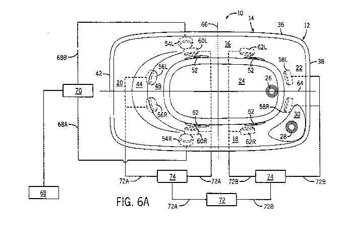
[0022] FIG. 6A is a schematic showing an exemplary
wiring layout of the system of FIG. 1;
[0023] FIG. 6B is _a schematic showing another
examplary wiring layout;
[0024] FIG. 7A is a schematic showing an examplary
signal distribution of the system of FIG. 1;
[0025] FIG. 7B is a schematic showing another
exemplary signal distribution;
[0026] FIG. 8A is a simplified waveform useable with
the system of FIG. 1 to establish a universal pulse;
[0027] FIG. 8B is another simplified waveform useable
with the system of FIG. 1 to establish a sweeping
vibration;
5
CA 02719854 2010-09-28
WO 2009/123690 PCT/US2009/001933
[0028] FIG. 8C is a further simplified waveform
useable with the system of FIG. 1 to establish a periodic
vibration;
[0029] FIG. 8D is yet another simplified waveform
useable with the system of FIG. 1 to establish a
predominate auditory experience;
[0030] FIG. 8E is an example auxiliary waveform
useable with the system of FIG. 1 to establish a
vibratory experience and an auditory experience from an
auxiliary input; and
[0031] FIG. 8F is an example basic waveform useable
with the system of FIG. 1 to establish a distinct
vibratory experience.
DETAILED DESCRIPTION OF EXAMPLE EMBODIMENT(S)
[0032] The present invention provides a vibroacoustic
water or bathing system in the form of a plumbing fixture
12 (preferably a bathtub) capable of simultaneously
producing and effecting to a bather 11 both controlled
auditory and vibratory experiences.
[0033] The auditory experience primarily imparts to
the bather 11 an aural stimulus that is produced by a
shell 14 driven in response to an audile signal that
incorporates wave characteristics under a traditional
musical framework. The musical framework includes typical
musical elements such as tones centered on a particular
key and harmonies related to the key. The auditory
experience preferably includes an audible melody of aural
focus that is heard by the bather 11. The auditory
experience is preferably propagated through a gaseous
medium, such as air, to the bather 11 and essentially
effects an aural stimulus.
[0034] The vibratory experience primarily imparts a
generally tactile stimulus to the bather 11 that is also
produced by a shell 14 driven in response to a vibratile
6
CA 02719854 2010-09-28
WO 2009/123690 PCT/US2009/001933
signal that incorporates wave characteristics that are
distinct from at least one of the wave characteristics of
the audile signal. The tactile vibrations of the
vibratory experience generally include non-melodic wave
characteristics specifically created to achieve a
controlled vibratory experience that is effected via a
tactile stimulus. The wave characteristics of the
vibratory experience preferably communicate a non-
discernable, ancillary experience that do not establish a
temporal framework, meaning that a typical adult bather
can be subjected to the same vibratile signal on multiple
occasions and not be able to readily consciously
distinguish the beginning, middle, end, or other temporal
relationships within a particular vibratory experience.
[0035] The vibratory experience is preferably
propagated through a liquid medium, such as water, to the
bather 11 and generally effects a tactile stimulus, such
as a deep massaging experience. Furthermore, the
vibratory experience preferably includes controlled
application of vibrations produced by the shell 14 to
manipulate the location and intensity of the vibratory
experience.
[0036] The vibroacoustic plumbing fixture 12, more
specifically the shell 14, has been "tuned" to customize
the auditory and vibratory experiences produced by the
shell 14 and propagated through the air and water to
effect the respective aural and tactile stimuli. The
shell 14 is preferably tuned to a desired key so as to
respond favorably to the predominant frequencies of the
particular key. A favorable shell 14 response generally
means that the shell 14 exhibits minimal vibratory
damping in the preferred range of frequencies at which
the shell 14 is configured to operate to enhance the
desired wave characteristics. The relationships between
7
CA 02719854 2010-09-28
WO 2009/123690 PCT/US2009/001933
the shell 14 and desired auditory and vibratory
experiences are established by relating the frequency
response of the shell 14 (e.g., the natural frequency and
harmonics of the shell 14) to the wave characteristics of
the desired auditory and vibratory experiences.
[0037] An example vibroacoustic plumbing fixture 12 is
shown in FIG. 1. The fixture or system 12 includes a
shell 14, such as a bathtub, shower stall, sink, or other
similar basin, that is preferably made of fiberglass
reinforced plastic, but may be made of a variety of other
materials and combinations of materials, such as acrylic,
metal, porcelain, and the like. The frequency response of
the shell 14 is partially dependent on the materials and
geometry of the shell 14. For example, depending on the
geometry, cast iron can be too dense and include too much
mass to establish a preferred vibroacoustic plumbing
fixture. However, with the appropriate geometry and
structure, a cast iron shell may be used in accordance
with the present invention. The geometry and materials of
the shell 14 are preferably customized to respond
favorably in the desired frequency range given the
specifics of each application and the wave
characteristics of the auditory and vibratory
experiences.
[0038] The shell 14 generally includes a left side
wall 16 offset from a right side wall 18, a head wall 20
offset from a foot wall 22, and a base 24 connecting the
walls 16, 18, 20, 22. The shell 14 is typically partially
filled with water via a spout controlled by a valve (not
shown). A drain 26 is formed in the base 24 to allow the
water to be emptied from the shell 14 when not in use.
Additionally, an overflow drain 28 is seated in an
overflow ledge 30 to ensure that water does not rise
8
CA 02719854 2010-09-28
WO 2009/123690 PCT/US2009/001933
above the waterline 32 and breach a plane 34 defined by a
rim 36 of the shell 14.
[0039] The foot end 38 of the shell 14 may include a
foot rest portion 40 having a contoured surface
configured to engage and support the feet of a user when
in the shell 14. Additionally, the head end 42 may
include a head pocket 44 formed above a backrest portion
48 of the head wall 20. The backrest portion 48 is sloped
and contoured to provide the bather 11 with a reclined
position once in the shell 14.
[0040] The head pocket 44 may take on a variety of
configurations. However, each is dimensioned and sized
such that when the head of a bather 11 rests in the head
pocket 44, the ears of bather 11 are essentially below
the plane 34, and preferably, above the waterline 32.
Keeping the ears below the rim 36 of the shell 14 and
above the waterline 32 alters the aural stimulus produced
by the shell 14 that is propagated through the air
(described in greater detail below). The head pocket 44
may alternatively be configured such that the ears are
located below the waterline 32. Again, the aural stimulus
effected by the auditory and vibratory experiences is
altered.
[0041] The vibroacoustic plumbing fixture 12 may also
include a series of chromotherapy devices 50 mounted to
the shell 14 that are generally synchronized with the
vibrations of the shell 14. The chromotherapy devices 50
may be comprised of multi-colored light emitting diodes,
filament bulbs, fiber optic strands, and the like, and
are housed behind translucent or transparent lenses 52.
The chromotherapy devices 50 can be mounted by any
technique known to those skilled in the art. Furthermore,
the location and quantity of the chromotherapy devices 50
can be altered as desired.
9
CA 02719854 2010-09-28
WO 2009/123690 PCT/US2009/001933
[0042] The vibroacoustic bathing system 12 includes a
plurality of transducers mounted in energy coupling
relation to the shell 14. The transducers drive and
vibrate the shell 14 thereby effecting the auditory and
vibratory experiences. While the example embodiment will
be described with reference to electromagnetic
transducers, the transducers may be of any type capable
of transforming an input signal into a corresponding
mechanical vibration. In the example embodiment, the
transducers are preferably electromagnetic Rolen-Star
Audio Transducers.
[0043] With specific reference to FIGS. 2, 6A, and 6B,
the transducers are divided between two groups: (1)
auditory transducers that vibrate the shell 14 to effect
the auditory experience and (2) vibratory transducers
that vibrate the shell 14 to effect the vibratory
experience. The auditory transducers include a right
audile transducer 54R and a left audile transducer 54L
(collectively the "audile transducers 54R, 54L"). The
vibratory transducers include a right head end vibratile
transducer 56R, a left head end vibratile transducer 56L,
a right foot end vibratile transducer 58R, a left foot
end vibratile transducer 58L, a right side head end
vibratile transducer 60R, a left side head end vibratile
transducer 60L, a right side foot end vibratile
transducer 62R, and a left side foot end vibratile
transducer 62L (collectively the "vibratile transducers
56R, 56L, 58R, 58L, 60R, 60L, 62R, 62L").
[0044] The example embodiment described uses a total
of two auditory transducers 54R, 54L and eight vibratory
transducers 56R, 56L, 58R, 58L, 60R, 60L, 62R, 62L;
however, any number of auditory and vibratory transducers
may be incorporated in accordance with the present
invention. In addition, while the preferred transducer
CA 02719854 2010-09-28
WO 2009/123690 PCT/US2009/001933
placement and quantity is shown, the placement of the
transducers may be altered, and in fact, are preferably
adjusted to accommodate a user's interaction with each
particular fixture 12 (e.g., bathtub) to maximize the
auditory and vibratory experiences. Given the shell 14
shown in the example embodiment, the transducers are
preferably placed in the relative arrangement as shown to
maximize the transmission of the wave characteristics
effected by the auditory and vibratory experiences. For
example, the audile transducers 54R, 54L are oriented as
shown to direct the auditory experience toward the bather
11 to effect the desired aural stimulus.
[0045] Each transducer is mounted in a location to
produce either, or both, a localized experience or an
overall experience. The vibratile transducers 56R, 56L,
58R, 58L, 60R, 60L, 62R, 62L are preferably mounted to
the shell 14 below the waterline 32 such that the
corresponding vibrations produce a tactile, vibratory
experience that propagates through the water.
[0046] As an example of a localized vibratory
experience, the right head end vibratile transducer 60R
and the left head end vibratile transducer 60L are
secured to the shell 14 proximate the backrest portion 48
such that energy produced by the right head end vibratile
transducer 60R and the left head end vibratile transducer
60L vibrate the shell 14 proximate the backrest portion
48 and produce a corresponding energy wave in the liquid
medium that propagates from the shell 14 to the bather
11. The vibratory experience is perceived tactilely by
the bather 11 as a controlled, directed vibration of the
back, chest, and all internal biological structures
proximate the right head end vibratile transducer 60R and
the left head end vibratile transducer 60L. Similar
controlled, localized effects are produced by the
11
CA 02719854 2010-09-28
WO 2009/123690 PCT/US2009/001933
remaining vibratile transducers 56R, 56L, 58R, 58L, 60R,
60L, 62R, 62L located at desired positions around the
shell 14.
[0047] The vibratile transducers 56R, 56L, 58R, 58L,
60R, 60L, 62R, 62L can also be controlled in concert to
produce an overall vibratory experience that propagates
to multiple regions or zones within the shell 14 or along
a predetermined path. In one embodiment, as shown in
FIGS. 6A and 7A, the right foot end vibratile transducer
58R and the left foot end vibratile transducer 58L can be
controlled in concert with the right head end vibratile
transducer 56R and the left head end vibratile transducer
5.6L to produce a controlled, combined vibratory
experience that propagates back and forth between the
feet and head of the bather 11. This provides a vibratory
experience having a tactile stimulus that propagates
through the bather 11 between the head and feet of the
bather 11.
[0048] In another embodiment, as shown in FIGS. 6B and
7B, the four centralized vibratile transducers, including
the right side head end vibratile transducer 60R, left
side head end vibratile transducer 60L, right side foot
end vibratile transducer 62R, and left side foot end
vibratile transducer 62L, are controlled in concert and
discretely from the four vibratile transducers proximate
the head end 42 and the foot end 38, including the right
head end vibratile transducer 56R, left head end
vibratile transducer 56L, right foot end vibratile
transducer 58R, and left foot end vibratile transducer
58L. This configuration can effect a tactile stimulus.
that selectively directs the vibratory experience between
the core and the head/feet of the bather 11. As one
skilled in the art will appreciate, a multitude of
12
CA 02719854 2010-09-28
WO 2009/123690 PCT/US2009/001933
transducer coupling configurations are available to
effect a vibratory experience to a bather 11.
[0049] The audile transducers 54R, 54L are preferably
mounted proximate the rim 36, essentially above the
waterline 32, and biased toward the head end 42 of the
shell 14. This places the audile transducers 54R, 54L
closer to the head of the bather 11 and essentially above
the water in the shell 14. As a result, the placement
enhances the auditory experience created by the audile
transducers 54R, 54L as the shell 14 vibrates the
surrounding air to effect the aural stimulus. Again, the
design of the shell 14, specifically the portion
proximate the rim 36, has been tuned to enhance the wave
characteristics of the auditory experience to maximize
the aural stimulus.
[0050] In the example embodiment, the right head end
vibratile transducer 56R, left head end vibratile
transducer 56L, right foot end vibratile transducer 58R,
and left foot end vibratile transducer 58L are generally
spaced apart along a longitudinal axis 64. Similarly, the
right side head end vibratile transducer 60R, left side
head end vibratile transducer 60L, right side foot end
vibratile transducer 62R, and left side foot end
vibratile transducer 62L are generally spaced apart along
a transverse axis 66. The right audile transducer 54R and
the left audile transducer 54L are also oriented
generally along the transverse axis 66.
[0051] This general orthogonal arrangement of the
transducers 54R, 54L, 56R, 56L, 58R, 58L, 60R, 60L, 62R,
62L allows the shell 14 to produce simultaneous auditory
and vibratory experiences that are dependent in part on
the relative spacing between and arrangement of the
transducers. The auditory and vibratory experiences may
include controlled application of the experiences,
13
CA 02719854 2010-09-28
WO 2009/123690 PCT/US2009/001933
including, panning, stereophonic imaging, focused
vibrations, and the like, within or between the quadrants
generally established by the longitudinal axis 64 and the
transverse axis 66. Additionally, the aural and tactile
stimuli of the auditory and vibratory experiences may be
controlled, for example, in location, amplitude,
frequency, duration, and interaction of the resulting
auditory and/or vibratory experiences. The wave
characteristics of the experiences can be manipulated to
effect a multitude of experiences.
[0052] The transducers 54R, 54L, 56R, 56L, 58R, 58L,
60R, 60L, 62R, 62L are mounted to the shell 14 by any
known means, including but not limited to adhesives and
epoxies, which securely couple the transducers 54R, 54L,
56R, 56L, 58R, 58L, 60R, 60L, 62R, 62L to the shell 14
and create an energy coupling relationship between the
shell 14 and the transducer. The preferred coupling
ensures an efficient transfer of energy from the
transducer 54R, 54L, 56R, 56L, 58R, 58L, 60R, 60L, 62R,
62L to the shell 14 such that the auditory experience and
the vibratory experience are sufficiently produced by the
shell to effect the desired aural and tactile stimuli.
[0053] With specific reference to FIG. 6A, a
simplified examplary general signal stream and wiring
schematic of the vibroacoustic bathing system 12 is
shown. For clarity, the audile components will be
described separately from the vibratile components.
Signal generation and processing will be described in
greater detail with reference to FIG. 7A.
[0054] The auditory experience is a result of the
audile signal 68 and its audile wave characteristics. The
audile signal 68 contains the instructions (i.e.,
characteristics) for the audile transducers 54R, 54L to
vibrate the shell 14 to produce the auditory experience
14
CA 02719854 2010-09-28
WO 2009/123690 PCT/US2009/001933
that is effected as an aural stimulus. The audile signal
68 is routed through an audile amplifier 70 before
driving the right audile transducer 54R and the left
audile transducer 54L. The audile signal 68 preferably
comprises a first audile channel 68A and a second audile
channel 68B. The first audile channel 68A drives the
right audile transducer 54R and the second audile channel
68B drives the left audile transducer 54L. The first
audile channel 68A and the second audile channel 68B can
carry a similar or distinct audile signal 68 to the
respective audile transducer 54R, 54L depending on the
desired auditory experience. For example, an aural
panning effect along the transverse axis 66 can be
accomplished by manipulating the audile wave
characteristics, such as the frequency and/or amplitude,
of the first audile channel 68A in concert with the
second audile channel 68B.
[0055] While the audile signal 68 of the example
embodiment is a two-channel signal, it is contemplated
that any other type of signal is equally applicable to
the current invention. For example, the audile signal 68
may be encoded such that information related to multiple
channels (e.g., 4, 5, 7, etc.) may be decoded from the
audile signal 68, amplified by one, or multiple, audile
amplifiers 70, and connected to the appropriate
transducers to produce the desired auditory experience.
[0056] The vibratory experience is a result of the
vibratile signal 72 and its vibratile wave
characteristics. The vibratile signal 72 contains the
instructions (i.e., characteristics) for the vibratile
transducers 56R, 56L, 58R, 58L, 60R, 60L, 62R, 62L to
produce the vibratory experience that is effected by a
tactile stimulus. In the example embodiment, the
vibratile signal 72 is routed through a pair of vibratile
CA 02719854 2010-09-28
WO 2009/123690 PCT/US2009/001933
amplifiers 74 before driving the vibratile transducers
56R, 56L, 58R, 58L, 60R, 60L, 62R, 62L. The vibratile
signal 72 preferably comprises a first vibratile channel
72A and a second vibratile channel 72B.
[0057] In one example embodiment shown in FIGS. 6A and
7A, the first vibratile channel 72A drives the right head
end vibratile transducer 56R, the left head end vibratile
transducer 56L, the right side head end vibratile
transducer 60R, and the left side head end vibratile
transducer 60L (collectively the "head end vibratile
transducers 56R, 56L, 60R, 60L"). The second vibratile
channel 72B drives the right foot end vibratile
transducer 58R, the left foot end vibratile transducer
58L, the right side foot end vibratile transducer 62R,
and the left side foot end vibratile transducer 62L
(collectively the "foot end vibratile transducers 58R,
58L, 62R, 62L").
[0058] As best shown in FIG. 6A, the right head end
vibratile transducer 56R and the left head end vibratile
transducer 56L are connected in series and the right side
head end vibratile transducer 60R and the left side head
end vibratile transducer 60L are also connected in
series. However, the head end vibratile transducers 56R,
56L, 60R, 60L are driven by the first vibratile channel
72A. A similar coupling is shown with respect to the foot
end vibratile transducers 58R, 58L, 62R, 62L that are
driven by the second vibratile channel 72B. The
configuration shown allows for the first vibratile
channel 72A and second vibratile channel 72B to drive the
respective head end vibratile transducers 56R, 56L, 60R,
60L and foot end vibratile transducers 58R, 58L, 62R, 62L
with two distinct vibratile signals 72. As a result, a
controlled vibratory experience can be effected by
varying the vibratile wave characteristics (e.g.,
16
CA 02719854 2010-09-28
WO 2009/123690 PCT/US2009/001933
intensity, duration, frequency, and the like), in
relation to the head end vibratile transducers 56R, 56L,
60R, 60L relative to the foot end vibratile transducers
58R, 58L, 62R, 62L. Thus the tactile stimulus of the
vibratory experience can be manipulated in position,
intensity, duration, and the like.
[0059] Another example embodiment is shown in FIGS. 6B
and 7B in which the first vibratile channel 72A drives
the right head end vibratile transducer 56R, the left
head end vibratile transducer 56L, the right foot end
vibratile transducer 58R, and the left foot end vibratile
transducer 58L (collectively the "end vibratile
transducers 56R, 56L, 58R, 58L"). The second vibratile
channel 72B drives the right side foot end vibratile
transducer 62R, the left side foot end vibratile
transducer 62L, the right side head end vibratile
transducer 60R, and the left side head end vibratile
transducer 60L (collectively the 'core vibratile
transducers 60R, 60L. 62R, 62L").
[0060] As best shown in FIG. 6B, the end vibratile
transducers 56R, 56L, 58R, 58L are driven by the first
vibratile channel 72A. Similarly, the core vibratile
transducers 60R, 60L, 62R, 62L are driven by the second
vibratile channel 72B. This transducer configuration
shown allows for the first vibratile channel 72A and
second vibratile channel 72B to drive the respective end
vibratile transducers 56R, 56L, 58R, 58L and core
vibratile transducers 60R, 60L, 62R, 62L with two
distinct vibratile signals 72. As a result, a controlled
vibratory experience can be effected by varying the
vibratile wave characteristics (e.g., intensity,
duration, frequency, and the like), in relation to the
end vibratile transducers 56R, 56L, 58R, 58L relative to
the core vibratile transducers 60R, 60L, 62R, 62L. Thus
17
CA 02719854 2010-09-28
WO 2009/123690 PCT/US2009/001933
the tactile stimulus of the vibratory experience can be
manipulated in position, intensity, duration, and the
like.
[0061] As with the first audile channel 68A and the
second audile channel 68B, the characteristics of the
first vibratile channel 72A and the second vibratile
channel 72B can be varied to create general or localized
vibratory experiences, such as panning from the foot end
38 to the head end 42. As with the audile transducers
54R, 54L, the vibratile transducers 56R, 56L, 58R, 58L,
60R, 60L, 62R, 62L each maybe driven by a separate and
discrete vibratile signal 72 that may be encoded in the
vibratile signal 72. Further, each vibratile transducer
56R, 56L, 58R, 58L, 60R, 60L, 62R, 62L can be driven by a
discrete vibratile amplifier 74, thus allowing
independent control, depending upon the application
requirements.
[0062] In the example embodiment, and with specific
reference to FIG. 7A, the auditory experience and the
vibratory experience are encoded into the audile signal
68 and the vibratile signal 72, respectively.
Alternatively, the audile signal 68 and the vibratile
signal 72 may be encoded into a single source signal and
decoded therefrom as necessary. Preferably, the audile
signal 68 and vibratile signal 72 are encoded in movie
Picture Experts Group Layer-3 format ("MP3 format"), but
may be encoded with any other codec or presented in raw
format (e.g., Waveform ("WAV"), Advanced Audio Coding
("AAC"), Dolby Digital, and the like).
[0063] The audile signal 68 and vibratile signal 72
are preferably extracted from separate media devices (not
shown) such as a Secure Digital ("SD") card, miniSD,
CompactFlash, flash drive, and the like. Alternatively,
the audile signal 68 and vibratile signal 72 may be
18
CA 02719854 2010-09-28
WO 2009/123690 PCT/US2009/001933
stored in a built-in storage media (e.g., a hard drive)
or on optical media (e.g., compact disc ("CD"), digital
versatile disk ("DVD"), Blue-ray Disk ("BD"), and the
like). Thus, the audile signal 68 and the vibratile
signal 72 may be extracted from a single media device and
from a single stream.
[0064] In the example embodiment, the audile signal 68
is directed to an audile decoder 76 where it is decoded
from MP3 format into a streaming audile signal 68
preferably comprising the first audile channel 68A and
the second audile channel 68B. Similarly, the vibratile
signal 72 is routed to a vibratile decoder 78 where it is
decoded from the preferred MP3 format to a streaming
vibratile signal 72 comprising the first vibratile
channel 72A and the second vibratile channel 72B. The
audile decoder 76 and the vibratile decoder 78 may be
similar to the SCF5250 Integrated ColdFire Microprocessor
produced by Freescale Semiconductor. Alternatively, a
single decoder may decode the audile signal 68 and the
vibratile signal 72.
[0065] The output from the audile decoder 76 (i.e.,
the first audile channel 68A and the second audile
channel 68B) and the vibratile decoder 78 (i.e., the
first vibratile channel 72A and the second vibratile
channel 72B) are directed into a controller 80. In the
example embodiment, the controller 80 can be any number
of complex programmable logic devices commonly available.
The controller 80 routes the first audile channel 68A,
second audile channel 68B, first vibratile channel 72A,
and second vibratile channel 72B to the appropriate input
on a signal processor 82 (described below). It should be
appreciated that the controller 80 may integrate one,
several, or all of the functions and features of the
decoders 76, 78, signal processor 82, amplifiers 70, 74,
19
CA 02719854 2010-09-28
WO 2009/123690 PCT/US2009/001933
chromotherapy controller 86, and any other component used
in the.vibroacoustic bathing system 12. The functions and
features of the various components of the example
embodiment have been separated for ease of explanation.
[0066] The controller 80 provides at least one chromo
signal 84 to a chromotherapy controller 86. The
chromotherapy controller 86 manipulates a series of
chromotherapy devices 50 (e.g., LEDs) in response to the
chromo signal 84 received from the controller 80. A
variety of color combinations, intensities, patterns, and
the like are directed into the shell 14 via the
chromotherapy controller 86 and integrated chromotherapy
devices 50.
[0067] The signal processor 82 of the example
embodiment manipulates and conditions the audile signal
68 and the vibratile signal 72. The signal processor 82
may be used to adjust the vibratile wave characteristics
or the audile wave characteristics, such as the frequency
and amplitude of the first audile channel 68A, second
audile channel 68B, first vibratile channel 72A, second
vibratile channel 72B, and any other input signal. The
signal processor 82 may be similar to the TAS5508A made
by Texas Instruments. Additionally, the signal processor
may include a series of amplifiers; however, the example
embodiment shown in FIGS. 6A and 7A incorporates an
audile amplifier 70 to drive the audile transducers 54R,
54L and a pair of vibratile amplifiers 74, one to drive
the head end vibratile transducers 56R, 56L, 60R, 60L and
one to drive the foot end vibratile transducers 58R, 58L,
62R, 62L. One skilled in the art will appreciate the
variety of amplifier configurations and combinations
available to power the vibroacoustic bathing system 12.
For example, a circuit board may include a series of
chips that include a pair of amplifiers each receiving an
CA 02719854 2010-09-28
WO 2009/123690 PCT/US2009/001933
input signal. The amplifiers may be electrically coupled
in a variety of ways to better distribute thermal energy
during operation, such as by electrically coupling one or
more chips.
[0068] With continued reference to FIG. 7A, the
configuration of the audile transducers 54R, 54L and
configuration of the head end vibratile transducers 56R,
56L, 60R, 60L and the foot end vibratile transducers 58R,
58L, 62R, 62L is illustrated. This example configuration
allows theaudile signal 68 to be discretely distributed
between the audile transducers 54R, 54L to achieve the
desired auditory experience. With reference to FIG. 7B,
the configuration of the end vibratile transducers 56R,
56L, 58R, 58L and core vibratile transducers 60R, 60L,
62R, 62L is illustrated. Additionally, the vibratile
signal 72 can be manipulated to be distributed between
the vibratile transducers 56R, 56L, 58R, 58L, 60R, 60L,
62R, 62L in a variety of ways to achieve the desired
vibratory experience.
[0069] As described above, each transducer 54R; 54L,
56R, 56L, 58R, 58L, 60R, 60L, 62R, 62L may be
independently controlled. For example, the controller 80
may output two distinct audile signals 68 and eight
distinct vibratile signals 72, allowing independent
control of each transducer 54R, 54L, 56R, 56L, 58R, 58L,
60R, 60L, 62R, 62L. For instance, a specific tactile
stimulus can be produced by a specific vibratile
transducer 56R, 56L, 58R, 58L, 60R, 60L, 62R, 62L by
sending a discrete vibratile signal 72 from the
controller 80 through the signal processor 82 and to the
desired vibratile transducer 56R, 56L, 58R, 58L, 60R,
60L, 62R, 62L.
[0070] The controller 80 of the example embodiment
also includes an auxiliary input 88. The controller 80
21
CA 02719854 2010-09-28
WO 2009/123690 PCT/US2009/001933
receives the auxiliary input 88 and routes the input to
the desired audile transducers 54R, 54L and vibratile
transducers 56R, 56L, 58R, 58L, 60R, 60L, 62R, 62L. The
signal may be sent to one or all of the transducers as
determined by the bather 11 via a user interface (not
shown) or by the controller 80 in accordance with
preprogrammed logic. For example, the controller 80 may
be programmed to filter the auxiliary input 88 to direct
lower frequencies (e.g., below approximately 250 hertz)
to the vibratile transducers 56R, 56L, 58R, 58L, 60R,
60L, 62R, 62L and higher frequencies (e.g., above
approximately 250 hertz) to the audile transducers 54R,
54L. Alternatively, the controller 80 may be programmed
to extract the pulsating signals (i.e., the "beat") from
the auxiliary input 88 and direct those signals to the
vibratile transducers 56R, 56L, 58R, 58L, 60R, 60L, 62R,
62L. The balance of the auxiliary input 88 would then be
directed to the audile transducers 54R, 54L. The
auxiliary input 88 may be obtained from a variety of
auxiliary devices (not shown) including a computer, a
television, a digital media player, and the like.
[0071] Turning to FIGS. 8A-8F, simplified waveforms
(whereat the Y-axis is generally representative of
relative amplitude and the X-axis is generally
representative of a temporal continuum) illustrating
example audile signals 68 and vibratile signals 72 that
are used to produce desired auditory and vibratory
experiences are shown. The audile signals 68 and
vibratile signals 72 illustrated are merely example
waveforms that can be used to produce a desired aural
stimulus and tactile stimulus by vibrating the shell 14.
The vibratory experience and the auditory experience have
at least one distinct wave characteristic as compared to
the other experience. The characteristic may be related
22
CA 02719854 2010-09-28
WO 2009/123690 PCT/US2009/001933
to frequency, amplitude, tone, duration, and any other
wave characteristic and are preferably tuned to the shell
14. Additionally, it is of note that the vibratory
experience and the auditory experience are preferably
produced simultaneously by the shell 14 to effect the
tactile and aural stimuli essentially simultaneously.
Therefore, the transducers simultaneously drive the shell
14 to produce the desired experiences.
[0072] With reference to FIG. 8A, the "letting go"
waveforms 90 are designed to create an auditory
experience and a vibratory experience that synchronize
certain biological metrics (e.g., breathing rate, heart
rate, and the like) of the bather 11 with a universal
pulse established by the "letting go" waveforms 90. The
auditory experience is imparted by the audile signal 68
that is directed via the first audile channel 68A and the
second audile channel 68B to the right audile transducer
54R and the left audile transducer 54L, respectively. The
auditory experience is then effected to the bather 11 as
the shell 14 vibrates the surrounding air as an aural
stimulus.
[0073] Similarly, in the embodiment shown in FIG. 6A,
the vibratory experience is imparted by the vibratile
signal 72 that is directed via the first vibratile
channel 72A to the head end vibratile transducers 56R,
56L, 60R, 60L, and the second vibratile channel 72B to
the foot end vibratile transducers 58R, 58L, 62R, 62L. In
the alternative embodiment shown in FIG. 6B, the
vibratory experience is imparted by the vibratile signal
72 that is directed via the first vibratile channel 72A
to the end vibratile transducers 56R, 56L, 58R, 58L, and
the second vibratile channel 72B to the core vibratile
transducers 60R, 60L, 62R, 62L. The vibrations imparted
to the shell 14 by the audile transducers 54R, 54L and
23
CA 02719854 2010-09-28
WO 2009/123690 PCT/US2009/001933
vibratile transducers 56R, 56L, 58R, 58L, 60R, 60L, 62R,
62L establish a. pulse that affects the bather 11 by
entraining the subconscious breathing pattern to the
repeating crescendos and decrescendos of the letting go
waveforms 90. As previously noted, the shell 14 vibrates
the water to propagate the vibratory experience; the
vibratory experience is ultimately effected as a tactile
stimulus. The vibratory experience effected by the
"letting go" waveform is one example of a biorhythmic
panning.
[0074] Turning to FIG. 8B, the "essence" waveforms 92
are designed to create an auditory experience and a
vibratory experience that again entrains the natural
rhythms of the bather 11 to the pulse of the essence
waveforms 92. In the embodiment shown in FIG. 6A, the
essence waveforms 92 create a vibratory experience in
which vibrations sweep from the foot. end 38 of the shell
14 to the head end 42 of the shell 14, and then from the
head end 42 to the foot end 38. Alternatively, the
embodiment shown in FIG. 6B creates a vibratory
experience in which vibrations pulse between the foot end
38 and head end 42, toward the transverse axis 66, and
back toward the foot end 38 and head end 42. Looking at
the vibratile signal 72, the peak amplitude Al of the
first vibratile channel 72A is temporally offset from the
peak amplitude A2 of the second vibratile channel 72B,
thus creating a sweeping vibratory experience as the
shell 14 vibrates.
[0075] With reference to the "transcendence" waveforms
94 shown in FIG. 8C, an additional exemplary set of
auditory and vibratory experiences are described. The
transcendence waveforms 94 establish a walking pulse
having a vibratile signal 72 establishing a periodic
vibratory experience that peaks repetitively
24
CA 02719854 2010-09-28
WO 2009/123690 PCT/US2009/001933
approximately one second apart. Specifically, the first
vibratile channel 72A is offset from the second vibratile
channel 72B such that a distinctive vibratory experience
is produced alternately proximate the head end 42 of the
shell 14 and the foot end 38 of the shell 14, in the
embodiment shown in FIG. 6A, and between the foot end 38/
head end 42 and the transverse axis 66 in the embodiment
shown in FIG. 6B, thereby establishing a rhythmic
vibration of the shell 14.
[0076] Turning to FIG. 8D, the "emergence" waveforms
96 are depicted and establish the auditory experience and
the vibratory experience. The average amplitude of the
audile signal 68 is notably greater than the vibratile
signal 72 average amplitude. Thus, the perceived
influence of the auditory experience effected via aural
stimulus is greater than the vibratory experiences
effected via tactile stimulus. As a result, the emergence
waveforms 96 cause the bather to focus on the auditory
experience more than the accompanying vibratory
experience.
[0077] The "auxiliary" waveforms 98 are illustrated in
FIG. 8E. The auxiliary waveforms 98 are indicative of the
audile signal 68 and vibratile signal 72 that may be
produced and routed to the respective audile transducers
54R, 54L and vibratile transducers 56R, 56L, 58R, 58L,
60R, 60L, 62R, 62L via the auxiliary input 88. In the
auxiliary waveforms 98 shown, no auxiliary input 88
manipulation is performed, however, as discussed above,
the signal may be manipulated (e.g., conditioned,
filtered, deconstructed, and the like) to achieve a
relative pre-determined auditory and vibratory
experience. For example, the vibratile signal 72 may be
analyzed to extract a pulse P that is in turn filtered
from the audile signal 68 and emphasized in the vibratile
CA 02719854 2010-09-28
WO 2009/123690 PCT/US2009/001933
signal 72. Additionally, the audile wave characteristics
and vibratile wave characteristics may be manipulated to
better interact with the shell 14 (i.e., be dynamically
tuned to the shell 14). Numerous additional signal
manipulation and processing techniques are within the
scope of the present invention and known to those in the
art.
[0078] In addition to the complex waveforms
illustrated in FIGS. 8A-8E, "basic" waveforms 100, such
as those shown in FIG. 8F, may be designed to impart an
auditory experience and a vibratory experience more akin
to a repetitive massage or drum beat. Many variations are
contemplated and within the scope of the present
invention.
[0079] As described above, the vibroacoustic bathing
system 12 can be configured to create a variety of
controlled auditory and vibratory experiences that are
effected as a result of the shell 14 vibrating to produce
both aural and tactile stimuli.
[0080] Preferred example embodiments of the present
invention have been described in considerable detail.
Many modifications and variations of the preferred
example embodiments described will be apparent to a
person of ordinary skill in the art. Therefore, the
invention should not be limited to the example
embodiments described.
INDUSTRIAL APPLICABILITY
[0081] The invention provides a vibroacoustic plumbing
fixture for use in consumer bathing applications,
specifically, a bathing system capable of producing
controlled auditory and vibratory experiences.
26