Note: Descriptions are shown in the official language in which they were submitted.
CA 02719922 2010-09-28
DESCRIPTION
PRESSURE CONTAINER, AND BUOYANT BODY AND EXPLORATORY
APPARATUS PROVIDED THEREWITH
Technical Field
The present invention relates to a pressure
container that accommodates measuring devices such as a
magnetometer for sea floor exploration and that can
exhibit a high pressure-resistant performance at a high
pressure in a deep sea, and a buoyant body and an
exploratory apparatus provided therewith.
Background Art
Pressure containers used in deep-sea research
activities are strongly required to be stronger and
lighter, and pressure-resistant structures for deep sea
applications are made of a titanium alloy or the like.
This sort of conventional technology is disclosed in
Japanese Unexamined Patent Publication JP-A 64-26065
(1989).
This conventional technology discloses a pressure
container made of a titanium alloy including one panel
portion corresponding to a semispherical first outer shell,
another panel portion corresponding to a semispherical
1
CA 02719922 2010-09-28
second outer shell, and a body portion corresponding to a
straight cylindrical third outer shell.
In this pressure container, a flange is formed at
each end portion of the body portion, a flange is formed
at an open edge portion of each of the panel portions, and
the flanges are connected with bolts and nuts for assembly.
Each flange of the body portion and each flange of the
panel portions are formed by cutting a forged material
made of a titanium alloy.
Furthermore, another conventional technology is
described in Non-Patent Document "Development Trend of
Foreign Deep-sea Technologies, Journal of Japan Deep Sea
Technology Association, 2007, No. 3". In this
conventional technology, use of ceramics instead of a
titanium alloy has been proposed, because, in the case
where a pressure container is made of a titanium alloy as
in the conventional technology of JP-A 64-26065(1989), the
specific gravity of the pressure container increases as
the resisting pressure depth increases, and the production
cost also increases.
Disclosure of Invention
Technical Problem
In the conventional technology described in JP-A 64-
26065(1989), stress generated by the water pressure at the
2
CA 02719922 2010-09-28
semispherical outer shells is different from that
generated at the straight cylindrical outer shell, and the
stress distribution becomes discontinuous at the portion
connecting these members. Thus, compared with
circumferential edge portions of the semispherical outer
shells, a large strain occurs at both end portions of the
straight cylindrical outer shell opposing the
circumferential edge portions of the semispherical outer
shells, which causes the problem that the reliability of
pressure-resistant performance and sealing performance is
low at the use environment in a deep sea at a water depth
of 1000 m or more.
This sort of problem occurs regardless of the shape
of a pressure container. For example, also in the case
where a pressure container is substantially in the shape
of a sphere obtained by connecting semispherical outer
shells, when the shapes of the outer shells are slightly
different from each other, or when the outer shells are
made of the same material but properties thereof are
slightly different from each other, stress generated at
each of the circumferential edge portions opposing each
other varies at some portions in the circumferential
direction, and the stress distribution becomes
discontinuous. Thus, the situation cannot be avoided in
which the reliability of pressure-resistant performance
3
CA 02719922 2010-09-28
and sealing performance is lowered at the portion
connecting these members. The pressure-resistant
performance and the sealing performance are desired to be
improved.
Furthermore, in the conventional technology
described in Non-Patent Document, use of ceramics instead
of a titanium alloy has been proposed, because, in the
case where a pressure container is made of a titanium
alloy, the specific gravity of the pressure container
increases as the resisting pressure depth increases, and
the production cost also increases. Furthermore, ceramics
has a compressive strength larger than that of a metal
material such as a titanium alloy, and, thus, in the case
where ceramics is used as a material of a pressure
container, a light and strong pressure container can be
produced. However, although the tensile strength of a
metal material is substantially equal to the compressive
strength thereof, the flexural strength of ceramics is
lower than the compressive strength thereof, and, thus,
when an approach for designing a metal pressure container
typified by JP-A 64-26065 is applied to ceramics without
any modification, large bending stress is generated at a
portion connecting the semispherical outer shells and the
straight cylindrical outer shells. Accordingly, in spite
of having a high compressive strength, the thickness of
4
CA 02719922 2010-09-28
the ceramic container has to be increased in order to
suppress the bending stress to a tolerance value or lower,
and, thus, it is problematic to use the container at a
high water pressure in view of pressure-resistant
performance and weight.
It is an object of the invention to solve the above-
described problems and to provide a pressure container
having improved reliability of pressure-resistant
performance and sealing performance at a connecting
portion between outer shells, and a pressure container
having light and strong outer shells, and a buoyant body
and an exploratory apparatus provided therewith.
Solusion to Problem
A pressure container of the invention comprises a
semispherical first outer shell made of ceramics, a
semispherical second outer shell made of ceramics, and an
annular connecting body interposed between the first outer
shell and the second outer shell and made of a material
having an elastic modulus smaller than those of the first
and second outer shells.
According to the invention, a first and a second
outer shell are made of ceramics, an annular connecting
body made of a material having an elastic modulus smaller
than those of the first and the second outer shells is
CA 02719922 2010-09-28
interposed between the first outer shell and the second
outer shell, and whereby a substantially spherical
pressure container is configured.
The connecting body interposed between the first and
the second outer shells is made of a material having an
elastic modulus smaller than those of the first and the
second outer shells made of ceramics, and, thus, at a
connecting portion where the circumferential edge portion
of the first outer shell and the circumferential edge
portion of the second outer shell oppose each other via
the connecting body, even when stress generated at the
circumferential edge portion of the first outer shell is
different from stress generated at the circumferential
edge portion of the second outer shell, use of a
connecting body having an elastic modulus smaller than
those of the first and the second outer shells disperses
and reduces stress generated at each of the
circumferential edge portions of the first and the second
outer shells. Accordingly, discontinuity can be
alleviated or eliminated, and, thus, the pressure-
resistant performance and the sealing performance are
improved.
Furthermore, a pressure container of the invention
comprises a semispherical first outer shell made of
ceramics, a semispherical second outer shell made of
6
CA 02719922 2010-09-28
ceramics, a straight cylindrical third outer shell made of
ceramics, and annular connecting bodies interposed between
the first outer shell and the third outer shell and
between the second outer shell and the third outer shell,
and made of materials at least one of which has an elastic
modulus smaller than those of the first to the third outer
shells.
According to the invention, a first and a second
outer shell and a third outer shell are made of ceramics,
and annular connecting bodies made of materials having an
elastic modulus smaller than those of the first and the
second outer shells are respectively interposed between
the first outer shell and the third outer shell and
between the second outer shell and the third outer shell.
The connecting bodies respectively interposed
between the first and the third outer shells and between
the second and the third outer shells are made of
materials having an elastic modulus smaller than those of
the first to the third outer shells made of ceramics, and,
thus, at a connecting portion where the circumferential
edge portion of the first outer shell and one of the
circumferential edge portions of the third outer shell
adjacent to the first outer shell oppose each other via
the connecting body, even when stress generated at the
circumferential edge portion of the first outer shell is
7
CA 02719922 2010-09-28
different from stress generated at the one circumferential
edge portion of the third outer shell, use of a connecting
body having an elastic modulus smaller than those of the
first to the third outer shells disperses stress generated
at each of the circumferential edge portions of the first
and the third outer shell, and discontinuity of the stress
is alleviated or eliminated.
Furthermore, at a connecting portion where the
circumferential edge portion of the second outer shell and
the other circumferential edge portion of the third outer
shell adjacent to the second outer shell oppose each other
via the connecting body, even when stress generated at the
circumferential edge portion of the second outer shell is
different from stress generated at the other
circumferential edge portion of the third outer shell, use
of a connecting body having an elastic modulus smaller
than those of the first to the third outer shells
disperses stress generated at each of the circumferential
edge portions of the second and the third outer shells,
and, thus, discontinuity is alleviated or eliminated.
In this manner, the pressure-resistant performance
and the sealing performance at a portion connecting the
first outer shell and the third outer shell and a portion
connecting the second outer shell and the third outer
shell are improved.
8
CA 02719922 2010-09-28
Advantageous Effects of Invention
According to the invention, an annular connecting
body made of a material having an elastic modulus smaller
than those of the first and the second outer shells is
interposed between the first outer shell and the second
outer shell, and, thus, discontinuity of the stress
generated at each of the circumferential edge portions of
first and the second outer shells can be alleviated or
eliminated, the pressure-resistant performance and the
sealing performance can be improved, and the thickness and
the weight of the members can be reduced.
According to the invention, annular connecting
bodies made of materials having an elastic modulus smaller
than those of the first to the third outer shells are
respectively interposed between the first outer shell and
the third outer shell and between the second outer shell
and the third outer shell, and, thus, stress generated at
each of the circumferential edge portions of the first and
the third outer shells is dispersed, and stress generated
at each of the circumferential edge portions of the second
and the third outer shells is dispersed. Thus,
discontinuity of the stress can be alleviated or
eliminated, the pressure-resistant performance and the
sealing performance can be improved, and the thickness and
9
CA 02719922 2010-09-28
the weight of the members can be reduced.
Brief Description of Drawings
Other and further objects, features, and advantages
of the invention will be more explicit from the following
detailed description taken with reference to the drawings
wherein:
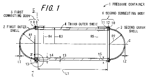
Fig. 1 is a cross-sectional view showing a pressure
container of an embodiment of the invention;
Fig. 2 is a cross-sectional view of a first
connecting body taken along line II-II in Fig. 1;
Fig. 3 is an enlarged cross-sectional view of
section III in Fig. 1;
Fig. 4A is an enlarged cross-sectional view showing
a state in which external pressure does not act on a
sealing member;
Fig. 4B is an enlarged cross-sectional view showing
a state in which low external pressure acts on the sealing
member;
Fig. 4C is an enlarged cross-sectional view showing
a state in which high external pressure acts on the
sealing member;
Fig. 5 is a cross-sectional view showing a testing
pressure container used in a pressure test for confirming
the pressure-resistant performance of the pressure
CA 02719922 2010-09-28
container according to the invention;
Fig. 6 is a graph showing a pressing load schedule
of the testing pressure container;
Fig. 7 is a cross-sectional view showing a pressure
container of another embodiment of the invention;
Fig. 8 is a view showing an unmanned exploratory
apparatus provided with the pressure container of the
embodiment shown in Fig. 1 or 7;
Fig. 9 is a view showing a towed deep-sea
exploratory apparatus provided with a pressure container
of another embodiment; and
Fig. 10 is a cross-sectional view showing a pressure
container of further another embodiment of the invention.
Reference signs list
1 Pressure container
la Pressure container
lb Pressure container
1A Pressure container
1B Pressure container
2 First outer shell
3 Second outer shell
4 Third outer shell
First connecting body
6 Second connecting body
11
CA 02719922 2010-09-28
7 Semisphere-side ring-shaped member
8 Cylinder-side ring-shaped member
9 Sealing member
Semisphere-side ring-shaped member
11 Cylinder-side ring-shaped member
12 Sealing member
13 Connector
Embedded portion
21 Projecting portion
22 Large-diameter portion
23 Small-diameter portion
24 Flange portion
Connecting portion
26 Seating face
Ring main body
31 Flange
33 Seal fitting groove
34 Fitting projection
Fitting recess
Back-up ring
41 Sealing member
C Common axis
Best Mode for Carrying out the Invention
Now referring to the drawings, preferred embodiments
12
CA 02719922 2010-09-28
of the invention are described below.
Fig. 1 is a cross-sectional view showing a pressure
container 1 of an embodiment of the invention. Fig. 2 is
a cross-sectional view of a first connecting body 5 taken
along line II-II in Fig. 1. The pressure container 1 of
this embodiment is configured by a semispherical first
outer shell 2 made of ceramics, a semispherical second
outer shell 3 made of ceramics, a straight cylindrical
third outer shell 4 made of ceramics, an annular first
connecting body 5 interposed between the first outer shell
2 and the third outer shell 4, and an annular second
connecting body 6 interposed between the second outer
shell 3 and the third outer shell 4. The first connecting
body 5 and the second connecting body 6 are made of a
material having an elastic modulus smaller than those of
the first to the third outer shells 2 to 4.
The first connecting body 5 has an annular
semisphere-side ring-shaped member 7 disposed on the side
of the first outer shell 2, an annular cylinder-side ring-
shaped member 8 disposed on the side of the third outer
shell 4, and a sealing member 9 interposed between the
semisphere-side ring-shaped member 7 and the cylinder-side
ring-shaped member 8. Furthermore, the second connecting
body 6 has an annular semisphere-side ring-shaped member
disposed on the side of the second outer shell 3, a
13
CA 02719922 2010-09-28
cylinder-side ring-shaped member 11 disposed on the side
of the third outer shell 4, and a sealing member 12
interposed between the semisphere-side ring-shaped member
and the cylinder-side ring-shaped member 11.
In this pressure container 1, in a state where the
first and the second outer shells 2 and 3 are respectively
connected via the first and the second connecting bodies 5
and 6 to both end portions in the axial direction of the
third outer shell 4, the axes of the first outer shell 2,
the second outer shell 3, the third outer shell 4, the
first connecting body 5, and the second connecting body 6
are on a common axis C that is a common straight line.
For example, the size and the shape of main portions
of the first to the third outer shells 2 to 4 and the
connecting bodies 5 and 6 will be described for reference.
The first outer shell 2 and the second outer shell 3 are
semispheres having radiuses Rl and R2 of the external
surfaces of 137.9 mm and thicknesses tl and t2 of 6.7 mm.
The third outer shell 4 is a straight cylinder having a
length L1 in the axial direction of 600 mm, a radius R3 of
the outer circumferential face of 144 mm, and a thickness
t3 of 19 mm. Furthermore, the first and the second
connecting bodies 5 and 6 have radiuses R4 and R5 of the
outer circumferential faces of 158 mm and thicknesses t4
and t5 of 34 mm.
14
CA 02719922 2010-09-28
Here, it is preferable that the first outer shell 2
and the second outer shell 3 have radiuses Rl and R2 of 50
to 500 mm and thicknesses tl and t2 of 2 to 20 mm, the
third outer shell 4 has a length Ll in the axial direction
of 200 to 1500 mm, a radius R3 of the outer
circumferential face of 50 to 500 mm, and a thickness t3
of 5 to 40 mm, and the first and the second connecting
bodies 5 and 6 have radiuses R4 and R5 of the outer
circumferential faces of 50 to 520 mm and thicknesses t4
and t5 of 10 to 100 mm.
In this embodiment, a plurality of connectors 13 are
arranged with intervals in the circumferential direction
on the cylinder-side ring-shaped member 8 of the first
connecting body 5 so as to be connected with cables for
electrically connecting various measuring devices
accommodated in the pressure container 1 and other
measuring apparatuses. The connectors 13 are radially
arranged on radial lines at each angle 0 in the
circumferential direction on a virtual plane perpendicular
to the common axis C. In this embodiment, the angle 0 is
set to 45 , but it is not limited thereto. For example,
in the case where 12 connectors 13 are arranged in the
circumferential direction, the angle 0 is set to 30 .
This sort of arrangement of the connectors 13 is
preferably determined in consideration of the shape of
CA 02719922 2010-09-28
constituent components such that, since external pressure
evenly acts in the circumferential direction of the
cylinder-side ring-shaped member 8, the connectors 13 are
arranged at even intervals, and the stress distribution of
stress generated at the cylinder-side ring-shaped member 8
is axisymmetric.
Fig. 3 is an enlarged cross-sectional view of
section III in Fig. 1. Each of the connectors 13 has an
embedded portion 20 embedded in the cylinder-side ring-
shaped member 8 and a projecting portion 21 externally
projecting from the cylinder-side ring-shaped member 8.
The embedded portion 20 has a short large-diameter portion
22 and a long small-diameter portion 23. Furthermore, the
projecting portion 21 has a flange portion 24 and a
connecting portion 25 projecting from the flange portion
24. Such connectors 13 may be made of an ordinarily used
metal such as stainless steel or a titanium alloy.
A flat seating face 26 perpendicular to a radius
about the common axis C is formed on the outer
circumferential portion of the cylinder-side ring-shaped
member 8 in order to uniformly obtain close contact with
the entire end face of the flange portion 24 of the
connector 13 facing the cylinder-side ring-shaped member 8.
This seating face 26 is formed at each position where the
connector 13 is attached, and the region between the
16
CA 02719922 2010-09-28
seating faces 26 on the outer circumferential face of the
cylinder-side ring-shaped member 8 is in the shape of a
straight cylinder. A width B of each seating face 26 on a
cross-section of rotation perpendicular to the radius
shown in Fig. 2 is, for example, 28 mm.
The cylinder-side ring-shaped member 8 has a ring
main body 30 whose cross-section obtained by cutting the
cylinder-side ring-shaped member 8 along a plane including
the common axis C is substantially rectangular and a
straight cylindrical flange 31 projecting from the end
face of the ring main body 30 facing the third outer shell
4. Furthermore, in the ring main body 30, a connector
attachment hole 32 to which the large-diameter portion 22
and the small-diameter portion 23 of the embedded portion
20 of the connector 13 are fitted, an annular seal fitting
groove 33 to which the sealing member 9 is fitted at the
side portion on the side of the semisphere-side ring-
shaped member 7, and a fitting projection 34 projecting
from the inner circumferential portion toward the
semisphere-side ring-shaped member 7 are formed. This
fitting projection 34 is fitted to a fitting recess 35
formed on the inner circumferential portion of the
semisphere-side ring-shaped member 7, and increases the
effective contact area between the semisphere-side ring-
shaped member 7 and the cylinder-side ring-shaped member 8,
17
CA 02719922 2010-09-28
thereby improving the sealing performance between the
semisphere-side ring-shaped member 7 and the cylinder-side
ring-shaped member 8.
Figs. 4A to 4C are enlarged cross-sectional views
for illustrating the function of the sealing member 9,
where Fig. 4A shows a state in which external pressure
does not act on the sealing member 9, Fig. 4B shows a
state in which low external pressure acts on the sealing
member 9, and Fig. 4C shows a state in which high external
pressure acts on the sealing member 9. The sealing member
9 is disposed in the seal fitting groove 33 of the
cylinder-side ring-shaped member 8, and is configured from
a back-up ring 40 disposed on the inner side in the radial
direction and a sealing member 41 disposed closer to the
outside in the radial direction than the back-up ring 40.
The back-up ring 40 is made of tetrafluoroethylene resin,
and the sealing member 41 (0-ring) is made of nitrile
rubber or ethylene propylene rubber, which have a rigidity
lower than that of the back-up ring.
In a state where external pressure does not act as
shown in Fig. 4A, the back-up ring 40 and the sealing
member 41 keep a relaxed state and are not deformed.
However, when external pressure acts, both of the back-up
ring 40 and the sealing member 41 are compressed inward in
the radial direction and deformed as shown in Fig. 4B.
18
CA 02719922 2010-09-28
Furthermore, when the external pressure is increased, the
back-up ring 40 and the sealing member 41 are
significantly deformed inward in the radial direction as
shown in Fig. 4C. This sort of deformation occurs in a
state where the back-up ring 40 and the sealing member 41
are sandwiched between a bottom face 42 in the seal
fitting groove 33 and an abutment face 43 of the
semisphere-side ring-shaped member 7 facing the cylinder-
side ring-shaped member 8, which opposes the bottom face
42, and, thus, the sealing member 41 is prevented by the
back-up ring 40 from being deformed inward in the radial
direction, and the contact area with the bottom face 42
and the abutment face 43 increases. When the external
pressure is increased, the close contact area increases,
and the sealing performance is improved.
Furthermore, the first outer shell 2 and the
semisphere-side ring-shaped member 7 may be fixed with an
adhesive (not shown). This adhesive can keep water-
tightness and reinforce the water-tightness. In a similar
manner, the third outer shell 4 and the cylinder-side
ring-shaped member 8 may be fixed with an adhesive, and
the water-tightness thereof may be reinforced with a
water-tight tape. Furthermore, although not shown, the
semisphere-side ring-shaped member 7 and the cylinder-side
ring-shaped member 8 may be fixed with bolts or bolts and
19
CA 02719922 2010-09-28
nuts. Accordingly, this portion can be easily separated.
Next, a method for producing the first to the third
outer shells 2 to 4 will be described. Examples of
ceramics used for the first to the third outer shells 2 to
4 include alumina, zirconia, silicon nitride, and silicon
carbide. Hereinafter, a method for producing a pressure
container using these materials will be described.
(1) Method for producing the first to the third
outer shells 2 to 4 using alumina
An alumina primary starting material having an
average particle size of approximately 1 pm is purchased.
Taking this primary starting material as 100% by mass, 1
to 5% by mass of sintering aid made of Ca, Si, and Mg
oxides, 1 to 1.5% by mass of binder containing PVA or the
like, 100% by mass of solvent, and 0.5% by mass of
dispersant are weighed, loaded into a container of an
agitator, and mixed and agitated to form a slurry. Then,
the slurry is granulated by a spray granulation (spray
drying) method to form a secondary starting material.
Then, this secondary starting material is molded by an
isostatic press molding (rubber pressing) method or a
powder press molding method, cut if necessary, and then
fired at a firing temperature of 1550 to 1700 C in an air
atmosphere in a firing furnace. After firing, final
finishing is performed by grinding, and, thus, a first to
CA 02719922 2010-09-28
a third outer shell 2 to 4 made of an alumina-based
sintered compact having a purity of 95% or more can be
obtained.
(2) Method for producing the first to the third
outer shells 2 to 4 using zirconia
A commercially available zirconia primary starting
material produced by a coprecipitation method and having
an average particle size of 0.1 m, to which 3 mol% of Y203
has been added, is purchased. Taking this primary
starting material as 100% by mass, 3% by mass of binder,
100% by mass of solvent, and 0.5% by mass of dispersant
are weighed, loaded into an agitator, and mixed and
agitated to form a slurry. Then, the slurry is granulated
by a spray granulation method (spray drying method) to
form a secondary starting material. Then, this secondary
starting material is molded by an isostatic press molding
(rubber pressing) method or a powder press molding method,
cut if necessary, and then fired at a firing temperature
of 1300 to 1500 C in an air atmosphere in a firing furnace.
After firing, final finishing is performed by grinding,
and, thus, a first to a third outer shell 2 to 4 made of a
zirconia-based sintered compact having a purity of 95% or
more can be obtained.
(3) Method for producing the first to the third
outer shells 2 to 4 using silicon nitride
21
CA 02719922 2010-09-28
A silicon nitride primary starting material powder
containing 1% by mass or less of Y203 and A1203r having a
purity of 99 to 99.8%, and having an average particle size
of 1 m is prepared. Taking this primary starting
material as 100% by mass, 1% by mass of binder, 0.5% by
mass or less of dispersant, and 100% by mass of solvent
are added to form a slurry. Then, this slurry is
granulated by a spray granulation method (spray drying
method) to form a secondary starting material. Then, this
secondary starting material is molded by an isostatic
press molding (rubber pressing) method or a powder press
molding method, cut if necessary, and then fired at a
maximum temperature of 1900 C in a nitrogen atmosphere in
a firing furnace. After firing, final finishing is
performed by grinding, and, thus, a first to a third outer
shell 2 to 4 made of a silicon nitride-based sintered
compact having a purity of 99% or more can be obtained.
(4) Method for producing the first to the third
outer shells 2 to 3 using silicon carbide
A sintering aid containing carbon (C) and boron (B),
alumina (A12O3) and yttria (Y203), or the like is added to
a silicon carbide primary starting material having an
average particle size of 0.5 to 10 m and having a purity
of 99 to 99.8% or more. The particle size of the mixture
is regulated using a pulverizer such as a ball mill such
22
CA 02719922 2010-09-28
that the average particle size is 1 m or less.
Furthermore, an appropriate amount of binder containing
polyethylene glycol, polyethylene oxide, or the like is
added to the resultant to form a slurry. Then, the slurry
is granulated by a spray granulation method (spray drying
method) to form a silicon carbide secondary starting
material. Then, this secondary starting material is
molded by an isostatic press molding method (rubber
pressing) or a powder press molding method, cut if
necessary, and then fired at a temperature of 1800 to
2200 C in a non-oxidizing atmosphere in a firing furnace.
After firing, final finishing is performed by grinding,
and, thus, a first to a third outer shell 2 to 4 made of a
silicon carbide-based sintered compact having a purity of
99% or more can be obtained.
Fig. 5 is a cross-sectional view showing a testing
pressure container 50 used in a pressure test for
confirming the pressure-resistant performance of the
pressure container according to the invention. Fig. 6 is
a graph showing a pressing load schedule of the testing
pressure container 50. In order to confirm the pressure-
resistant performance of the pressure container, the
inventors performed a pressure test using the testing
pressure container 50. The testing pressure container 50
had a length L1 in the axial direction of 218.2 mm, the
23
CA 02719922 2010-09-28
first to the third outer shells 2 to 4 were made of a
silicon nitride-based sintered compact (manufactured by
Kyocera Corporation: SN-240), the semisphere-side ring-
shaped members 7 and 10 of the first and the second
connecting bodies 5 and 6 were made of a zirconia-based
sintered compact (manufactured by Kyocera Corporation: Z-
201), the cylinder-side ring-shaped members 8 and 11 of
the first and the second connecting bodies 5 and 6 were
made of stainless steel (SUS630), and the first and the
second connecting bodies 5 and 6 had an outer diameter D
of 122.2 mm.
This sort of testing pressure container 50 was used
to perform a pressure test twice. In the first pressure
test, the pressure was increased to 60 MPa at a pressure
increasing speed of 1 MPa/min, this pressurized state was
maintained for 15 minutes, and, then, the pressure was
reduced to 0 MPa at a pressure reducing speed of 1 MPa/min.
In this test, significant deformation such as crushing was
not seen in the pressure container 50, and leakage of
water into the container did not occur.
Next, in the second pressure test, the pressure was
increased to 120 MPa at a pressure increasing speed of 2
MPa/min, this pressurized state was maintained for 15
minutes, and, then, the pressure was reduced to 0 MPa at a
pressure reducing speed of 2 MPa/min. Also in this test,
24
CA 02719922 2010-09-28
significant deformation such as crushing was not seen in
the pressure container 50, and leakage of water into the
container did not occur. Thus, it was confirmed that the
pressure container according to the invention had
pressure-resistant performance at a high pressure of 120
MPa corresponding to a pressure at a water depth of
approximately 12,000 m.
Furthermore, with a computer simulation using a
finite element method, the inventors confirmed that, when
pressure was applied to the pressure container according
to the invention, the deformation amounts of the end
portion of the semispherical first outer shell 2 in
contact with the semisphere-side ring-shaped member 7 and
the end portion of the straight cylindrical third outer
shell 4 in contact with the cylinder-side ring-shaped
member 8 in the thickness direction of the semisphere-side
ring-shaped member 7 could be accurately obtained with
respect to the theoretical values. The analytical method
used in the finite element method was a stress analysis of
a linear isotropic elastic body, in which non-linear
elements of material, geometric shape, and boundary
condition are not included, and only elastic modulus E and
Poisson's ratio are used as material constant data for
describing behavior. In a governing equation, when a
rigidity matrix is taken as K, a displacement vector is
CA 02719922 2010-09-28
taken as u, and a load vector is taken as f, the load-
displacement relationship in a linear static analysis is
expressed as below.
Ku = f ... (1)
When known boundary conditions are given for displacement
and load, Expression (1) can be expressed as below.
r11 K12 u, _ f ... (2)
K21 K22 u2 f2
Here, u1r fl, u2, and f2 are respectively an unknown
displacement vector, a known load vector, a known
displacement vector, and an unknown reaction force vector.
When the expression is solved for the displacement u,
strain can be obtained as below using the strain-nodal
displacement relationship in the element.
el = RUel ... (3)
Next, stress can be obtained using the following formula
by a stress-strain function L.
Gel = LCel ... (4)
Here, Gel and Eel are stress and strain in the element,
and Uel is a displacement vector of a node constituting
that element. (3 represents a strain displacement, and L
represents a stress-strain relationship.
According to this embodiment, operation and effects
as shown in the following examples are obtained.
(Example 1)
26
CA 02719922 2010-09-28
Pressure containers were produced in which the first
to the third outer shells 2 to 4 were made of metal (a
titanium alloy) and ceramics (an ordinarily used alumina-
based sintered compact). When comparison was performed
regarding the weight and the deformation amount in the
case where pressure was applied to the pressure containers
loaded in a pressurized water tank, basically, the ceramic
pressure container was more resistant to compression
stress (water pressure in this example), and less deformed
than the metal pressure container.
When a titanium alloy (specific gravity 4.5, elastic
modulus approximately 100 GPa) and an alumina-based
sintered compact (specific gravity 3.8 to 3.9, elastic
modulus 350 GPa) are compared, the alumina-based sintered
compact has a smaller specific gravity, a higher
compressive strength, and a larger elastic modulus than
the titanium alloy, and, thus, the alumina-based sintered
compact is deformed less even when compression weight due
to water pressure is applied. Accordingly, the thickness
and the weight can be reduced.
Furthermore, in the first to the third outer shells
2 to 4 made of an alumina-based sintered compact, the
connecting bodies 5 and 6 used between the first outer
shell 2 and the third outer shell 4 and between the second
outer shell 2 and the third outer shell 4 are preferably
27
CA 02719922 2010-09-28
made of materials that have an elastic modulus smaller
than those of the first to the third outer shells 2 to 4
as in the semisphere-side ring-shaped members 7 and 10
made of a zirconia-based sintered compact and the
cylinder-side ring-shaped members 8 and 11 made of
stainless steel, and that are different from each other.
In the case where the connecting bodies 5 and 6 were made
of a plurality of ring-shaped members, and at least one of
these members had an elastic modulus smaller than those of
the first to the third outer shells 2 to 4, stress
generated at each of the circumferential edge portions of
the first and the second outer shells 2 and 3 and the
third outer shell 4 was dispersed, discontinuity of the
stress was alleviated or eliminated, and the pressure-
resistant performance and the sealing performance could be
improved.
(Example 2)
Pressure containers were produced in which the first
to the third outer shells 2 to 4 were made of ceramic
materials that were an alumina-based sintered compact (as
in Example 1), a zirconia-based sintered compact, a
silicon nitride-based sintered compact, and a silicon
carbide-based sintered compact. In a pressure test in a
pressurized water tank, the pressure was increased to 120
MPa at a pressure increasing speed of 2 MPa/min, this
28
CA 02719922 2010-09-28
pressurized state was maintained for 15 minutes, and, then,
the pressure was reduced to 0 MPa at a pressure reducing
speed of 2 MPa/min. As a result, in all pressure
containers, leakage of water into the pressure containers
did not occur, and good results were obtained. It was
confirmed that, in particular, the pressure container made
of a silicon nitride-based sintered compact was excellent
because the weight thereof can be reduced.
(Example 3)
Pressure containers were produced in which the
material and the number (practically, the number up to
five was possible) of the ring-shaped members respectively
constituting the connecting bodies 5 and 6 of the pressure
container 1 in the foregoing embodiment where the first to
the third outer shells 2 to 4 were made of a silicon
nitride-based sintered compact were changed. In a
pressure test as in Examples 1 and 2, leakage of water
into the pressure containers did not occur, and it was
confirmed that good results for pressure-resistant
performance were obtained.
It was confirmed that, regarding the material of the
ring-shaped members respectively constituting the
connecting bodies 5 and 6, the semisphere-side ring-shaped
members 7 and 10 were preferably made of ceramics (an
alumina-based sintered compact, a zirconia-based sintered
29
CA 02719922 2010-09-28
compact) having an elastic modulus smaller than those of
the first to the third outer shells 2 to 4, the cylinder-
side ring-shaped members 8 and 11 were preferably made of
metal or ceramics, and, in particular, ceramics used for
the semisphere-side ring-shaped members 7 and 10 was
preferably a zirconia-based sintered compact.
(Example 4)
In order to compare the case in which the open
porosity of the first to the third outer shells 2 to 4 is
more than 3% and the case in which the open porosity is 3%
or less, first, a silicon nitride primary starting
material powder containing 1% by mass or less of Y203 and
A1203 and having a purity of 99 to 99.8% was prepared.
Taking this primary starting material as 100 mass%, 1% by
mass of binder, 0.5% by mass or less of dispersant, and
100% by mass of solvent were added to form a slurry. Then,
this slurry was granulated by a spray granulation method
(spray drying method) to form a secondary starting
material powder. Then, this secondary starting material
was molded by an isostatic press molding (rubber pressing)
method or a powder press molding method, cut if necessary,
and then fired at a maximum temperature of 1900 C in a
nitrogen atmosphere in a firing furnace. After firing,
final finishing was performed by grinding, and, thus, a
first to a third outer shell 2 to 4 made of a silicon
CA 02719922 2010-09-28
nitride-based sintered compact and having a purity of 99%
or more were produced in which the open porosity was 4% as
the case where the open porosity was more than 3%, and in
which the open porosity was 3% as the case where the open
porosity was 3% or less. Then, comparison was performed
regarding the pressure-resistant performance of these
outer shells.
The range of open porosity can be increased by
producing a silicon nitride primary starting material
powder such that the ranges of average particle size (open
pores increase as the average particle size increases) and
firing temperature (open pores increase as the firing
temperature is lowered) are increased.
When pressure containers using the first to the
third outer shells 2 to 4 made of a silicon nitride-based
sintered compact having open porosities of 4% and 3%,
obtained by adjusting the average particle size and the
firing temperature of the primary starting material powder,
were produced, and the pressure-resistant performance was
confirmed, leakage of water into the pressure containers
did not occur, and it was confirmed that good results for
pressure-resistant performance were obtained.
(Example 5)
In this example, in order to prevent surface damage
of the first to the third outer shells 2 to 4, the surface
31
CA 02719922 2010-09-28
of the first to the third outer shells 2 to 4 (the outer
shells were similar to those in Example 4) was coated with
a resin. The resin used for coating was urethane in this
example, but tetrafluoroethylene resin, epoxy resin,
polyethylene resin, and the like may be used in other
examples of the invention.
Furthermore, the surface of the first to the third
outer shells 2 to 4 made of a silicon nitride-based
sintered compact having the open porosities set to 4%, 3%,
1%, and 0.1% by adjusting the average particle size and
the firing temperature of the primary starting material
powder may be coated with the above-described resin. In
the case where the open porosity was set to 4%, due to an
anchor effect in which a resin flows into open pores on
the surface of the silicon nitride-based sintered compact,
the adhesiveness of the resin became good, and the shock
resistance against a shock from the outside could be
improved. Furthermore, in the case where the open
porosity was set to 3% or less, a good adhesiveness was
obtained without substantially lowering the strength of
the first to the third outer shells 2 to 4, and the shock
resistance against a shock from the outside could be
improved. Thus, it was confirmed that the first to the
third outer shells 2 to 4 coated with a resin preferably
have an open porosity of 3% or less, and were particularly
32
CA 02719922 2010-09-28
preferably made of a silicon nitride-based sintered
compact from the viewpoint of the weight reduction.
(Example 6)
Furthermore, the surface of the first to the third
outer shells 2 to 4 made of ceramics may be processed so
as to have arithmetic mean roughnesses (Ra) of 0.3 m, 0.5
m, 1 m, 5 m, 10 m, and 12 m, and the surface of the
first to the third outer shells 2 to 4 may be coated with
a resin. In pressure containers produced using these
outer shells, as the arithmetic mean roughness (Ra) of the
surface of the first to the third outer shells 2 to 4 was
smaller, the surface of the first to the third outer
shells 2 to 4 coated with a resin was smoother, and, thus,
friction with water was smaller, and a good driving force
in water could be obtained. Furthermore, as the
arithmetic mean roughness (Ra) of the surface of the first
to the third outer shells 2 to 4 was larger, the resin was
firmly attached to the rough surface of the first to the
third outer shells 2 to 4, and a good adhesiveness could
be obtained due to the anchor effect. Accordingly, it was
confirmed that the arithmetic mean roughness (Ra) of the
surface of the first to the third outer shells 2 to 4 was
preferably 0.5 m or more and 10 m or less in order to
obtain a good driving force in water and a good
adhesiveness.
33
CA 02719922 2010-09-28
Here, examples of the method for processing the
surface of the first to the third outer shells 2 to 4 made
of ceramics to the above-described arithmetic mean
roughness (Ra) include sandblasting and etching. In
particular, when the surface of the compact is sandblasted
and then fired, the arithmetic mean roughness (Ra) of the
surface of the first to the third outer shells 2 to 4 can
be adjusted to a good range.
Furthermore, the arithmetic mean roughness (Ra) of
the surface of the first to the third outer shells 2 to 4
can be measured using a contact-type or non-contact-type
surface roughness meter as defined in JIS B 0601-2001, for
example, with condition setting according to JIS standard
(JIS B 0601 3, JIS B 0633 4, JIS B 0031 Appendixes G and
F) in which the cut-off value (sampling length) is 0.8 mm
and the evaluation length is 4 mm.
Fig. 7 is a cross-sectional view showing a pressure
container la of another embodiment of the invention. Here,
constituent components corresponding to those in the
foregoing embodiment are denoted by the same reference
numerals. The pressure container la of this embodiment
includes the semispherical first outer shells 2 made of
ceramics, the semispherical second outer shells 3 made of
ceramics, and an annular connecting body 60 interposed
between the first outer shell 2 and the second outer shell
34
CA 02719922 2010-09-28
3 and made of a material having an elastic modulus smaller
than those of the first and the second outer shells 2 and
3.
The connecting body 60 has the semisphere-side ring-
shaped member 7 disposed on the side of the first outer
shell 2, the semisphere-side ring-shaped member 10
disposed on the side of the second outer shell 3, an
annular intermediate ring-shaped member 61 interposed
between the semisphere-side ring-shaped members 7 and 10,
and the sealing members 9 and 12 interposed between the
semisphere-side ring-shaped members 7 and 10 and the
annular intermediate ring-shaped member 61. As in the
foregoing embodiment, the first and the second outer
shells 2 and 3 are made of one selected from alumina,
zirconia, silicon nitride, and silicon carbide.
Furthermore, it is important that the ring-shaped members
7 and 10 constituting the connecting body 60 are made of a
material having an elastic modulus smaller than those of
the first and the second outer shells 2 and 3, and can be
made of a titanium alloy, stainless steel, or ceramics.
As in the foregoing embodiment, also in the thus
configured substantially spherical pressure container la,
the connecting body 60 interposed between the first and
the second outer shells 2 and 3 made of ceramics is made
of a material having an elastic modulus smaller than those
CA 02719922 2010-09-28
of the first and the second outer shells 2 and 3, and,
thus, at a connecting portion where the circumferential
edge portion of the first outer shell 2 and the
circumferential edge portion of the second outer shell 3
oppose each other via the connecting body 60, even when
stress generated at the circumferential edge portion of
the first outer shell 2 is different from stress generated
at the circumferential edge portion of the second outer
shell 3, use of the connecting body 60 having an elastic
modulus smaller than those of the first and the second
outer shells 2 and 3 disperses and reduces stress
generated at each of the circumferential edge portions of
the first and the second outer shells 2 and 3.
Accordingly, discontinuity in stress and strain can be
alleviated or eliminated, and, thus, the pressure-
resistant performance and the sealing performance can be
improved.
Fig. 8 is a view showing an unmanned exploratory
apparatus 71 provided with the pressure container 1 or la
of the embodiment shown in Fig. 1 or 7. The exploratory
apparatus 71 is configured by a propulsive unit 74 that is
moored by a primary cable 73 extended from a watercraft 72
on the sea surface, and an exploratory unit 75 that is
detachably attached to the propulsive unit 74 and explores
the deep sea. The pressure container 1 functions not only
36
CA 02719922 2010-09-28
as a pressure container that can resist a water pressure
in a very deep sea at a water depth of 1000 m to 11,000 m
but also as a buoyant body, and is mounted on a side
portion of the exploratory unit 75.
Fig. 9 is a view showing a towed deep-sea
exploratory apparatus 80 provided with a pressure
container of another embodiment. The towed deep-sea
exploratory apparatus 80 is configured by a sinker 82 that
is attached to a main wire 81 extended from the watercraft
72 on the sea surface, a pressure container 1A that is
connected via a rope 83 to the sinker 82, and a pressure
container 1B that is connected via a cable 84 to the
pressure container 1A, and can measure a magnetic force of
geomagnetism, for example, by accommodating a proton
magnetometer in the pressure container lA, accommodating a
magnetometer sensor in the pressure container 1B, and
towing the pressure containers at a depth of approximately
500 m above the sea floor.
(Example 7)
Pressure containers 1 were respectively produced in
which the first to the third outer shells 2 to 4 were made
of a titanium alloy, alumina, and silicon nitride. A
plurality of such pressure containers were mounted on the
exploratory unit 75 of the unmanned exploratory apparatus
71 shown in Fig. 8, and comparison was performed regarding
37
CA 02719922 2010-09-28
the weight ratio of the buoyant bodies with respect to the
total weight of the exploratory unit 75. As a result,
when the pressure containers made of a titanium alloy were
used as buoyant bodies, the weight ratio of the buoyant
bodies with respect to the total weight was 50% or more.
On the other hand, when the pressure containers made of
alumina were used as buoyant bodies, the weight ratio of
the buoyant bodies with respect to the total weight was 40
to 50%, and the weight ratio of the buoyant bodies could
be reduced. Furthermore, when the pressure containers
made of silicon nitride were used as buoyant bodies, the
weight ratio of the buoyant bodies with respect to the
total weight was 30 to 40%, and the weight ratio of the
buoyant bodies could be further reduced.
In this manner, in the case where the first to the
third outer shells 2 to 4 constituting the pressure
container 1 are made of ceramics, the weight ratio of the
buoyant bodies can be reduced compared with the case where
the outer shells are made of a titanium alloy.
Accordingly, the weight of the exploratory apparatus 71
can be reduced, and the load amount of materials collected
from the deep-sea floor (e.g., research samples such as
deep-sea organisms and minerals) can be increased.
Furthermore, since the weight ratio of the buoyant bodies
can be reduced, the efficiency of research operations in a
38
CA 02719922 2010-09-28
deep sea and the fuel efficiency can be improved.
Furthermore, since an annular connecting body made of a
material having an elastic modulus smaller than those of
the first to the third outer shells 2 to 4 is interposed,
discontinuity of generated stress can be eliminated,
occurring strain can be alleviated, the amounts of the
circumferential edge portions opposing each other at the
connecting portion contracted by water pressure can be
equalized, and generation of bending stress and shearing
stress can be suppressed. Accordingly, the thickness of
the first to the third outer shells 2 to 4 can be reduced,
and, thus, the specific gravity of the entire pressure
container can be adjusted to less than 1. Accordingly, it
was confirmed that, although the pressure container had a
high specific strength (= compressive strength / specific
gravity) and a high strength, the pressure container could
generate a buoyant force in water, and could function also
as a buoyant body.
The invention can be applied to pressure containers
of not only unmanned exploratory apparatuses in a deep sea
but also sea floor-installed or sea-floating observation
apparatuses, and can be preferably used in other marine
observation apparatuses as well.
In the foregoing embodiments, the pressure
containers 1 and la have been described that are
39
CA 02719922 2010-09-28
configured such that the outer diameter of the connecting
bodies 5 and 6 or the outer diameter of the connecting
body 60 is larger than the outer diameter of the first to
the third outer shells 2 to 4 and the outer diameter of
the first and the second outer shells 2 and 3, but, in
another embodiment of the invention, a pressure container
lb may be configured such that the outer diameter of the
first to the third outer shells 2 to 4 is the same as the
outer diameter of the connecting bodies 5 and 6 as shown
in Fig. 10. Furthermore, in a similar manner, a
substantially spherical pressure container as shown in Fig.
7 may be configured such that the outer diameter of the
connecting body 60 and the first and the second outer
shells 2 and 3 is the same as the outer diameter of the
connecting body 60. Also in this pressure container lb,
as in the pressure containers 1 and la in the foregoing
embodiments, since an annular connecting body made of a
material having an elastic modulus smaller than those of
the first to the third outer shells 2 to 4 is interposed
at a portion connecting the semispherical first and second
outer shells and the straight cylindrical third outer
shell and a portion connecting the semispherical first and
second outer shells, discontinuity of generated stress can
be eliminated, occurring strain can be alleviated, the
amounts of the circumferential edge portions opposing each
CA 02719922 2010-09-28
other at the connecting portion contracted by water
pressure can be equalized, and generation of bending
stress and shearing stress can be suppressed.
The invention may be embodied in other specific
forms without departing from the spirit or essential
characteristics thereof. The present embodiments are
therefore to be considered in all respects as illustrative
and not restrictive, the scope of the invention being
indicated by the appended claims rather than by the
foregoing description and all changes which come within
the meaning and the range of equivalency of the claims are
therefore intended to be embraced therein.
41