Note: Descriptions are shown in the official language in which they were submitted.
CA 02720204 2010-11-05
BATTERY POWERED ELECTROSURGERY
BACKGROUND
1. Technical Field
[00011 The present disclosure relates to apparatuses for providing energy to
biological tissue and. more particularly, to a portable electrosurgical device
for providing
energy to biological tissue.
2. Background of Related Art
[00021 Energy-based tissue treatment is well known in the art. Various types
of
energy (e.g., electrical, ultrasonic, microwave, cryogenic, thermal, laser,
etc.) are applied
to tissue to achieve a desired result. Electrosurgery involves application of
high radio
frequency electrical current to a surgical site to cut, ablate, coagulate or
seal tissue. In
monopolar electrosurgery, as shown in Fig. IA. a source or active electrode 2
delivers
radio frequency energy from the electrosurgical generator 20 to the tissue and
a return
electrode 2 carries the current back to the generator. In monopolar
electrosurgery, the
source electrode is typically part of the surgical instrument held by the
surgeon and
applied to the tissue to be treated. A patient return electrode is placed
remotely from the
active electrode to carry the current back to the generator.
[00031 In bipolar electrosurgery, as shown in Fig. 1 B, one of the electrodes
of the
hand-held instrument functions as the active electrode 14 and the other as the
return
electrode 16. The return electrode is placed in close proximity to the active
electrode such
that an electrical circuit is formed between the two electrodes (e.g.,
electrosurgical
forceps 10). In this manner, the applied electrical current is limited to the
body tissue
-I-
CA 02720204 2010-11-05
positioned immediately adjacent to the electrodes. When the electrodes are
sufficiently
separated from one another, the electrical circuit is open and thus
inadvertent contact with
body tissue with either of the separated electrodes does not cause current to
flow.
[0004] Electrosurgical instruments have become widely used by surgeons in
recent years. By and large, most electrosurgical instruments are hand-held
instruments,
e.g., an electrosurgical pencil, which transfer radio-frequency (RF)
electrical or
electrosurgical energy to a tissue site. As used herein the term
"electrosurgical pencil" is
intended to include instruments which have a handpiece that is attached to an
active
electrode and which is used to cauterize, coagulate and/or cut tissue.
Typically, the
electrosurgical pencil may be operated by a handswitch or a foot switch. The
active
electrode is an electrically conducting element that is usually elongated and
may be in the
form of a thin flat blade with a pointed or rounded distal end. Alternatively,
the active
electrode may include an elongated narrow cylindrical needle that is solid or
hollow with
a flat, rounded, pointed or slanted distal end. Typically electrodes of this
sort are known
in the art as "blade", "loop" or "snare", "needle" or "ball" electrodes.
[00051 As mentioned above, the handpiece of the electrosurgical pencil is
connected to a suitable electrosurgical energy source (i.e., generator) which
produces the
radio-frequency electrical energy necessary for the operation of the
electrosurgical pencil.
In general, when an operation is performed on a patient with an
electrosurgical pencil,
electrical energy from the electrosurgical generator is conducted through the
active
electrode to the tissue at the site of the operation and then through the
patient to a return
electrode. The return electrode is typically placed at a convenient place on
the patient's
body and is attached to the generator by a conductive material.
-2-
CA 02720204 2010-11-05
[00061 Some electrosurgical procedures utilize electrosurgical forceps that
use
both mechanical clamping action and electrical energy to affect hemostasis by
heating
tissue and blood vessels to coagulate, cauterize and/or seal tissue. As an
alternative to
open forceps for use with open surgical procedures, many modern surgeons use
endoscopes and endoscopic instruments for remotely accessing organs through
smaller,
puncture-like incisions. As a direct result thereof, patients tend to benefit
from less
scarring and reduced healing time.
[00071 Endoscopic instruments are typically inserted into the patient through
a
cannula, or port, which has been made with a trocar. Typical sizes for
cannulas range
from three millimeters to twelve millimeters. Smaller cannulas are usually
preferred,
which, as can be appreciated, ultimately presents a design challenge to
instrument
manufacturers who must find ways to make endoscopic instruments that fit
through the
smaller cannulas. Such endoscopic instruments may use monopolar forceps,
bipolar
forceps or a combination monopolar/bipolar forceps.
100081 Most electrosurgical procedures are performed in a hospital setting due
to
the need of a generator to supply energy to the electrosurgical instrument.
Such
generators tend to be large and generally expensive. Thus, electrosurgical
procedures can
not be performed in the field by first responders or military personnel nor
can it be
performed in a clinical setting where the purchase of a permanent generator is
cost
prohibitive.
-3-
CA 02720204 2010-11-05
SUMMARY
[00091 In an embodiment of the present disclosure, an electrosurgical device
is
provided that includes a housing including a cavity defined therein for
housing an
electrosurgical energy source, a controller configured to control the output
of the
electrosurgical energy source, and a power supply configured to supply power
to the
electrosurgical energy source and the controller. The housing may also include
an active
port configured to be operatively coupled to an end effector, wherein the end
effector
applies electrosurgical energy from the electrosurgical energy source to
tissue, and a
return port configured to be operatively coupled to a return pad to provide a
return path
for the electrosurgical energy applied to tissue.
100101 The power supply for the electrosurgical device may be a battery which
may be selectively replaceable or rechargeable. Further, the electrosurgical
energy
source outputs the electrosurgical energy in the form of a sine waveform, a
square
waveform, a pulse width modulated signal or a saw tooth waveform.
[00111 In another embodiment of the present disclosure, an electrosurgical
pencil
is provided having an elongated housing. The housing including a cavity
defined therein
for housing an electrosurgical energy source, a controller configured to
control the output
of the electrosurgical energy source and a power supply configured to supply
power to
the electrosurgical energy source and the controller. The housing may also
include a
return port configured to be operatively coupled to a return pad, an
electrocautery
electrode supported within the housing and extending distally from the
housing, the
electrocautery electrode being connected to the electrosurgical energy source
and a
plurality of activation switches supported on the housing, each activation
switch being
-4-
CA 02720204 2010-11-05
configured and adapted to selectively complete a control loop extending from
the
electrosurgical energy source upon actuation thereof.
[0012] In the electrosurgical pencil, at least one activation switch is
configured
and adapted to control a waveform duty cycle to achieve a desired surgical
intent. The
pencil may also include three mode activation switches supported on the
housing,
wherein each mode activation switch delivers a characteristic signal to the
source of
electrosurgical energy which in turn transmits a corresponding waveform duty
cycle to
the electrosurgical pencil. A first activation switch delivers a first
characteristic signal to
the source of electrosurgical energy which in turn transmits a waveform duty
cycle which
produces a cutting effect, a second activation switch delivers a second
characteristic
signal to the source of electrosurgical energy which in turn transmits a
waveform duty
cycle which produces a blending effect, and a third activation switch delivers
a third
characteristic signal to the source of electrosurgical energy which in turn
transmits a
waveform duty cycle which produces a coagulating effect.
[0013] The power supply of the electrosurgical pencil may be a battery that is
selectively replaceable and/or rechargeable.
[0014] In another embodiment of the present disclosure, an endoscopic forceps
is
provided having a housing having a shaft attached thereto. The housing
including a
cavity defined therein for housing an electrosurgical energy source, a
controller
configured to control the output of the electrosurgical energy source, a power
supply
configured to supply power to the electrosurgical energy source and the
controller, and a
return port configured to be operatively coupled to a return pad. The shaft
includes a pair
of jaw members disposed at a distal end thereof. The endoscopic forceps also
includes a
-5-
CA 02720204 2010-11-05
drive assembly disposed in the housing operable to move the jaw members
relative to one
another from a first position, wherein the jaw members are disposed in spaced
relation
relative to one another, to a second position, wherein the jaw members are
closer to one
another, for manipulating tissue. Each jaw member is adapted to connect to the
electrosurgical energy source such that the jaw members are capable of
conducting
energy for treating tissue. A first switch is disposed on the housing and is
activatable to
selectively deliver energy of a first electrical potential to at least one jaw
member for
treating tissue in a monopolar fashion and a second switch is disposed on the
housing and
is activatable to selectively deliver energy of a first electrical potential
to one jaw
member and selectively deliver energy of a second electrical potential to the
other jaw
member for treating tissue in a bipolar fashion.
[00151 The power supply of the electrosurgical pencil may be a battery that is
selectively replaceable or rechargeable.
BRIEF DESCRIPTION OF THE DRAWINGS
[00161 The above and other aspects, features, and advantages of the present
disclosure will become more apparent in light of the following detailed
description when
taken in conjunction with the accompanying drawings in which:
[00171 Figs. 1 A-I B are schematic diagrams of electrosurgical systems;
[00181 Fig. 2 is a schematic block diagram of an electrosurgical system
according
to an embodiment of the present disclosure for use with various instrument
types;
[00191 Fig. 3 is a schematic block diagram of an electrosurgical system
according
to another embodiment of the present disclosure for use with various
instrument types;
-6-
CA 02720204 2010-11-05
[00201 Fig. 4 is a perspective view of an electrosurgical pencil in accordance
with
an embodiment of the present disclosure;
[00211 Fig. 5 is a plan view of the electrosurgical pencil of Fig. 4;
[00221 Fig. 6 is a side, elevational view of the electrosurgical pencil of
Fig. 4;
[00231 Fig. 7 is a partially broken away, side elevational view of the
electrosurgical pencil of Fig. 4;
[00241 Fig. 8 is a front, elevational view of the electrosurgical pencil of
Fig. 4;
[00251 Fig. 9 is a side, elevational view of an electrosurgical pencil
according to
an embodiment of the present disclosure;
[00261 Fig. 10 is a plan view of the electrosurgical pencil of Fig. 9;
[00271 Fig. 11 is a front, perspective view of a distal end portion of an
electrosurgical pencil according to an embodiment of the present disclosure;
[00281 Fig. 12 is a front, perspective view of a distal end portion of an
electrosurgical pencil according to an embodiment of the present disclosure;
[0029] Fig. 13 is an enlarged, perspective view of a portion of an
electrosurgical
pencil illustrating a set of switches disposed thereon;
[0030] Fig. 14 is an enlarged, perspective view of a portion of an
electrosurgical
pencil illustrating another set of switches disposed thereon; and
[0031] Fig. 15 is a perspective view of the switch of Fig. 14;
[00321 Fig. 16A is a top, perspective view of an endoscopic forceps shown in
an
open configuration and including a housing, a handle assembly, a shaft and an
end
effector assembly according to the present disclosure;
-7-
CA 02720204 2010-11-05
[0033] Fig. 16B is a top, perspective view of the endoscopic forceps of Fig.
16A
showing the end effector assembly in a closed configuration according to the
present
disclosure;
[0034] Fig. 17 is a bottom, perspective view of the endoscopic forceps of Fig.
16A;
[0035] Fig. 18 is top, perspective view of the forceps of Fig. 16B showing
rotation of the end effector assembly;
[0036] Fig. 19A is an enlarged, left perspective view of an end effector
assembly;
[0037] Fig. 19B is an enlarged, left perspective view of an end effector
assembly
in a closed configuration;
[0038] Fig. 19C is an enlarged, side view of the end effector assembly;
[0039] Fig. 19D is an enlarged, end view of the end effector assembly;
[0040] Fig. 20A is a greatly-enlarged, top cross sectional view of the end
effector
assembly showing a knife of the knife actuator in a proximal-most or
unactuated position;
[0041] Fig. 20B is a greatly-enlarged, top cross sectional view of the end
effector
assembly of Fig. 31A showing the position of the knife after actuation;
[0042] Fig. 21A is a greatly-enlarged, side cross sectional view of the end
effector
assembly shown in an open configuration;
[0043] Fig. 21B is a greatly-enlarged, side cross sectional view of the end
effector
assembly shown in a closed configuration;
[0044] Fig. 21C is a greatly-enlarged, front perspective view of a bottom jaw
member of the end effector assembly showing the knife of the knife actuator in
a
proximal-most or unactuated position;
-8-
CA 02720204 2010-11-05
[00451 Fig. 21D is a greatly-enlarged, front perspective view of the bottom
jaw
member of Fig. 21C showing the position of the knife after actuation;
100461 Fig. 22A is a greatly-enlarged, perspective view of the bottom jaw of
the
end effector assembly with parts separated; and
[0047j Fig. 22B is a greatly-enlarged, perspective view of the top jaw of the
end
effector assembly with parts separated.
DETAILED DESCRIPTION
[0048[ Particular embodiments of the present disclosure are described
hereinbelow with reference to the accompanying drawings; however, it is to be
understood that the disclosed embodiments are merely exemplary of the
disclosure and
may be embodied in various forms. Well-known functions or constructions are
not
described in detail to avoid obscuring the present disclosure in unnecessary
detail.
Therefore, specific structural and functional details disclosed herein are not
to be
interpreted as limiting, but merely as a basis for the claims and as a
representative basis
for teaching one skilled in the art to variously employ the present disclosure
in virtually
any appropriately detailed structure.
[00491 Like reference numerals may refer to similar or identical elements
throughout the description of the figures. As shown in the drawings and
described
throughout the following description, as is traditional when referring to
relative
positioning on a surgical instrument, the term "proximal" refers to the end of
the
apparatus which is closer to the user and the term "distal" refers to the end
of the
apparatus which is further away from the user.
-9-
CA 02720204 2010-11-05
[00501 Electromagnetic energy is generally classified by increasing energy or
decreasing wavelength into radio waves, microwaves, infrared, visible light,
ultraviolet,
X-rays and gamma-rays. As used herein, the term "microwave" generally refers
to
electromagnetic waves in the frequency range of 300 megahertz (MHz) (3 x 10⁸
cycles/second) to 300 gigahertz (GHz) (3 x 10lt cycles/second). As used
herein, the term
"RF" generally refers to electromagnetic waves having a lower frequency than
microwaves.
[00511 Fig. 2 shows a block diagram of an electrosurgical system 30 according
to
an embodiment of the present disclosure. As shown in Fig. 2, system 30
includes an
active electrode 32, a return electrode 34 and a handpiece 36. Active
electrode 32 is
operatively coupled to handpiece 36 and may be an end effector such as
monopolar
forceps, bipolar forceps, a combination monopolar/bipolar forceps or a blade
that may
include a planar blade, a loop, a needle or the like. Return electrode 34 may
be an RF
return pad that is operatively coupled to handpiece 36. As such,
electrosurgical system
30 is a portable device that is not limited for use in a hospital or clinical
setting, but may
also be used in the field by first responders and the military.
[00521 Return electrode 34 (or RF return pad 34) may have any suitable regular
or irregular shape such as circular or polygonal. RF return pad 34 may be a
conductive
pad that may include a plurality of conductive elements arranged in a regular
or irregular
array. Each of the plurality of conductive elements may be equally-sized or
differently-
sized and may form a grid/array on the conductive pad. The plurality of
conductive
elements may also be arranged in a suitable spiral or radial orientation on
the conductive
pad. The use of the term "conductive pad" as described herein is not meant to
be limiting
-10-
CA 02720204 2010-11-05
and may indicate a variety of different pads including, but not limited to,
conductive,
inductive, or capacitive pads.
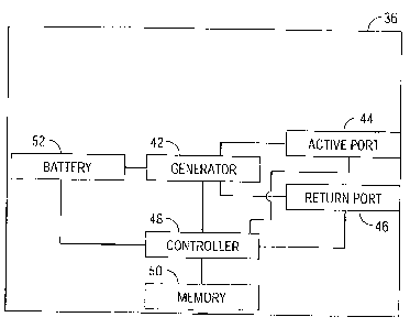
[00531 Fig. 3 shows a representative block diagram of the handpiece 36
according
to an embodiment of the present disclosure. As shown in Fig. 3, handpiece 36
has a
generator 42 that generates and outputs electrosurgical energy to the active
port 44 that is
coupled to an active electrode 32 or end effector (Fig. 2). The
electrosurgical energy
output from the generator 42 is sufficient to cut, cauterize, coagulate, seal
or ablate tissue.
The electrosurgical energy may be outputted as a sine waveform, square
waveform, a
pulse-width modulated (PWM) signal, a saw tooth waveform or any other waveform
set
by a manufacturer or a user that would accomplish the effects desired by the
user of the
electrosurgical device. The handpiece also has a return port 46 that receives
energy from
the return electrode 34.
[00541 The controller 48 may include a microcontroller operably connected to a
memory 50, which may be volatile type memory (e.g., RAM) and/or non-volatile
type
memory (e.g., flash media, disk media, etc.). The microcontroller includes an
output port
that is operably connected to the generator 42 allowing the microcontroller to
control the
output of the microwave generator 42. Those skilled in the art will appreciate
that the
microcontroller may be substituted by any logic controller (e.g., control
circuit) adapted
to perform the calculations discussed herein. Memory 50 may be used to store a
set of
instructions, reference values, or other programming that may be used by the
controller
48 to control the output of the generator 42. The controller may also include
an input
port configured to receive a signal from the active port 44 representative of
the output
energy and to receive a signal from the return port 46 representative of the
return energy.
-11-
CA 02720204 2010-11-05
Based on the signals from the active port 44 and return port 46, the
controller may adjust
the output of the generator 42.
[0055] The components in handpiece 36, such as generator 42 and controller 48,
may be powered by a power supply or battery 52. Battery 52 may be a primary
battery
that transforms chemical energy to electrical energy or a secondary battery
that can be
recharged.
[0056] Turning now to Figs. 4-8, an electrosurgical pencil constructed in
accordance with an embodiment of the present disclosure is shown generally as
100.
Commonly owned U.S. Patent Application Serial No. 10/718,113 entitled
"ELECTROSURGICAL PENCIL WITH 3-D CONTROLS" (now U.S. Patent No.
7,156,844), the contents of which are herein incorporated by reference in
their entirety.
Electrosurgical pencil 100 includes an elongated housing 102, which may be
similar to
handpiece 36 of Fig. 3, configured and adapted to support a blade receptacle
104 at a
distal end 103 thereof which, in turn, receives a replaceable electrocautery
end effector
106 in the form of a loop and/or blade therein. Electrocautery blade 106 is
understood to
include a planar blade, a loop, a needle and the like. A distal end portion
108 of blade
106 extends distally from receptacle 104 while a proximal end portion of blade
106 is
retained within distal end 103 of housing 102. Electrocautery blade 106 may be
fabricated from a conductive type material, such as, for example, stainless
steel, or is
coated with an electrically conductive material. The electrosurgical pencil
also includes
an electrosurgical energy source or generator "G", a controller "C" and a
battery "B" (see
Fig. 7).
-12-
CA 02720204 2010-11-05
100571 As shown, electrosurgical pencil 100 is coupled to a return pad "R" via
a
cable 112. Cable 112 includes a transmission wire which electrically
interconnects return
pad "R" with return port 111 of electrosurgical pencil 100. Connecting return
pad "R"
directly to the electrosurgical pencil precludes the need for a separate
generator and/or
controller.
[0058[ For the purposes herein, the terms "switch" or "switches" includes
electrical actuators, mechanical actuators, electro-mechanical actuators
(rotatable
actuators, pivotable actuators, toggle-like actuators, buttons, etc.) or
optical actuators.
[0059[ Electrosurgical pencil 100 includes at least one activation switch,
preferably three activation switches 124a-124c, each of which are supported on
an outer
surface 107 of housing 102. Each activation switch 124a-124c is operatively
connected
to a respective switch 126a-126c which, in turn, controls the transmission of
RF electrical
energy supplied from generator "G" to electrosurgical blade 106. More
particularly,
switches 126a-126c are electrically coupled to control loop 116 and are
configured to
close and/or complete control loop 116 to thereby permit RF energy to be
transmitted to
electrocautery blade 106 from electrosurgical generator "G".
[00601 Activation switches 124a-124c are configured and adapted to control the
mode and/or "waveform duty cycle" to achieve a desired surgical intent in the
same
manner as activation switches 24a-24c of electrosurgical pencil 10 described
above.
[00611 Electrosurgical pencil 100 further includes at least one intensity
controller
128a and/or 128b, each of which are slidingly supported in guide channels
130a, 130b,
respectively, which are formed in outer surface 107 of housing 102. Each
intensity
controller 128a and 128b is a slide-like potentiometer. It is contemplated
that each
-13-
CA 02720204 2010-11-05
intensity controller 128a and 128b and respective guide channel 130a and 130b
may be
provided with a series of cooperating discreet or detented positions defining
a series of
positions to allow easy selection of output intensity from a minimum amount to
a
maximum amount. The series of cooperating discreet or detented positions also
provide
the surgeon with a degree of tactile feedback. One of the series of positions
for intensity
controllers 128a, 128b may be an "off' position (i.e., no level of electrical
or RF energy is
being transmitted).
[0062] Intensity controllers 128a and 128b are configured and adapted to
adjust
one of the power parameters (e.g., voltage, power and/or current intensity)
and/or the
power verses impedance curve shape to affect the perceived output intensity.
[0063] For example, the greater intensity controllers 128a, 128b are displaced
in a
distal direction (i.e., in the direction of electrocautery blade 106) the
greater the level of
the power parameters transmitted to electrocautery blade 106. Conceivably,
current
intensities can range from about 60 mA to about 240 mA when using an
electrosurgical
blade and having a typical tissue impedance of about 2000 ohms. An intensity
level of
60 mA provides very light and/or minimal cutting/dissecting/hemostatic
effects. An
intensity level of 240 mA provides very aggressive
cutting/dissecting/hemostatic effects.
Accordingly, the preferred range of current intensity is from about 100 mA to
about 200
mA at 2K ohms.
[0064) The intensity settings may be preset and selected from a look-up table
based on a choice of electrosurgical instruments/attachments, desired surgical
effect,
surgical specialty and/or surgeon preference. The selection may be made
automatically
-14-
CA 02720204 2010-11-05
or selected manually by the user. The intensity values may be predetermined or
adjusted
by the user.
[0065] In operation and depending on the particular electrosurgical function
desired, the surgeon depresses one of activation switches 124a-124c, in the
direction
indicated by arrow "Y" (see Figs. 4 and 7) thereby closing a corresponding
switch 126a-
126c and closing and/or completing control loop 116. For example, the surgeon
can
depress activation switch 124a to perform a cutting or dissecting function,
activation
switch 124b to perform a dissecting/hemostatic function, or activation switch
124c to
perform a hemostatic function. In turn, generator "G" transmits an appropriate
waveform
output to electrocautery blade 106 via transmission wire 114.
[0066] In order to vary the intensity of the power parameters of
electrosurgical
pencil 100, e.g., the current intensity, the surgeon displaces at least one of
intensity
controllers 128a, 128b in the direction indicated by double-headed arrow "X".
As
mentioned above, the intensity can be varied from approximately 60 mA for a
light effect
to approximately 240 mA for a more aggressive effect. For example, by
positioning one
of intensity controllers 128a, 128b closer to the proximal-most end (i.e.,
closer to cable
112) a light effect is produced and by positioning one of intensity
controllers 128a, 128b
closer to the distal-most end (i.e., closer to electrocautery blade 106) a
more aggressive
effect is produced. As described above, each intensity controller 128a, 128b
can be
configured and adapted to provide a degree of tactile feedback. Alternatively,
audible
feedback can be produced from each intensity controller 128a, 128b (e.g., a
"click"),
electrosurgical energy source "G" (e.g., a "tone") and/or an auxiliary sound-
producing
device such as a buzzer (not shown).
-15-
CA 02720204 2010-11-05
[0067] As shown in Fig. 7, electrosurgical pencil 100 may include a power
source
or battery "B", a controller "C" and an electrosurgical energy source or
generator "G"
within housing 102. Battery "B" supplies power to controller "C" and generator
"G" and
may be a primary battery or a secondary battery. Controller "C" receives
inputs from the
various switches, intensity controller, nubs, potentiometers or the like that
may be
disposed in housing 102 and outputs a signal to generator "G". Generator "G"
provides
electrosurgical energy based on the signal provided by controller "C".
[0068] In an alternative embodiment, as seen in Figs. 9 and 10, sliding
intensity
controllers 128a, 128b have been replaced with intensity controllers 228a,
228b in the
form of dial-like VDNs. Intensity controllers 228a, 228b function to vary the
intensity of
the power parameters via a rotation of dial controllers 228a, 228b in either a
clockwise or
counter-clockwise direction as indicated by double headed arrow "Z".
[0069] Fig. 11 depicts an alternative embodiment of an electrosurgical pencil
shown generally as 200. Electrosurgical pencil 200 is similar to
electrosurgical pencil
100 and will only be discussed in detail to the extent necessary to identify
differences in
construction and operation. As seen in Fig. 11, electrosurgical pencil 200
includes a
plurality of nubs, e.g., three nubs, 229a-229c that are each operatively
engaged with a
slide potentiometer.
[0070] Accordingly, electrosurgical pencil 200 can be configured such that
each
activation switch 24a-24c is a separate mode, such as, for example, activation
switch 24a
can be set such that electrosurgical pencil 200 performs "division" when
depressed,
activation switch 24b can be set such that electrosurgical pencil 200 performs
"division
with hemostasis" when depressed, and activation switch 24c can be set such
that
-16-
CA 02720204 2010-11-05
electrosurgical pencil 200 performs "hemostasis" when depressed. In addition,
each nub
229a-229c is in operative engagement with a corresponding activation switch
24a-24c
such that the power for each mode of operation of electrosurgical pencil 200
can be
independently adjusted. As seen in Fig. 12, nubs 229a-229c of electrosurgical
pencil 200
have been replaced with toggles 231a-231c operatively engaged with a
respective
activation switch 24a-24c. Each toggle 231 a-231 c can be operatively engaged
with a
rocker-type switch (not shown) or a rotational dial (not shown) in place of
the slide-type
potentiometer described above.
[00711 Turning now to Figs. 13-15, an electrosurgical pencil, in accordance
with
still another embodiment of the present disclosure, is generally designated as
300.
Electrosurgical pencil 300 is similar to electrosurgical pencil 100 and will
only be
discussed in detail to the extent necessary to identify differences in
construction and
operation. As seen in Figs. 13 and 14, a dial 329 is rotatably supported in an
aperture 330
formed in outer surface 107 of housing 102. A side surface 331 of dial 329 can
be
provided with indicia and/or markings "M" in the form of a scale and/or other
form of
gradient to indicate to the surgeon the degree of and/or level of power at
which
electrosurgical pencil 300 is set. As seen in Figs. 14 and 15, windows 332 can
be formed
on either side of dial 329 in outer surface 107 of housing 102. As seen in
Fig. 15,
windows 332 provide the surgeon with visibility to indicia "M" provided on
stub 333
extending from the central axis of dial 329.
[00721 Embodiments of the present disclosure may also be incorporated into
endoscopic instruments such as the instruments disclosed in commonly owned
U.S.
-17-
CA 02720204 2010-11-05
Patent Application Serial No. 11/540,335 entitled "IN-LINE VESSEL SEALER AND
DIVIDER", the contents of which are herein incorporated by reference in their
entirety.
[00731 Turning now to Figs. 16A-17, one embodiment of a combination
endoscopic bipolar and monopolar forceps 400 is shown for use with various
surgical
procedures and generally includes a housing 420, a handle assembly 430, a
rotating
assembly 480, a knife trigger 470 and an end effector assembly 1100 which
mutually
cooperate to grasp, seal and divide tubular vessels and vascular tissue (Figs.
32A and
32B).
100741 Forceps 400 includes a shaft 412 which has a distal end 416 dimensioned
to mechanically engage the end effector assembly 1100 and a proximal end 414
that
mechanically engages the housing 420. Handle assembly 430 includes two movable
handles 430a and 430b disposed on opposite sides of housing 420. Handles 430a
and
430b are movable relative to one another to actuate the end effector assembly
1100 as
explained in more detail below with respect to the operation of the forceps
400. Rotating
assembly 480 is mechanically coupled to housing 420 and is rotatable
approximately 90
degrees in either direction about a longitudinal axis "A" (see Figs. 16A-18).
[00751 As mentioned above, end effector assembly 1100 is attached at the
distal
end 416 of shaft 412 and includes a pair of opposing jaw members 1110 and 1120
(See
Figs. 19A-19D). Handles 430a and 430b of handle assembly 430 ultimately
connect to
the drive assembly in forceps 400 which, together, mechanically cooperate to
impart
movement of the jaw members 1110 and 1120 from an open position wherein the
jaw
members 1110 and 1120 are disposed in spaced relation relative to one another,
to a
-18-
CA 02720204 2010-11-05
clamping or closed position wherein the jaw members 1110 and 1120 cooperate to
grasp
tissue (Figs. 21 A and 21 B) therebetween.
[0076] Housing 420 may be similar to handpiece 36 of Fig. 3. That is, housing
420 may also include a battery, a controller and a generator. The battery
supplies power
to the controller and the generator and may be a primary battery or a
secondary battery.
The controller receives inputs from the various switches, intensity
controller, nubs,
potentiometers or the like that may be disposed in forceps 400 and outputs a
signal to the
generator. The generator provides electrosurgical energy based on the signal
provided by
the controller.
[0077] Similar to electrosurgical pencil 100 described above, forceps 400
includes a cable 410 coupled to return port 404. The other end of cable 410 is
coupled to
a return pad (not shown). Connecting the return pad directly to forceps 400
precludes the
need for a separate generator and/or controller.
[0078] End effector assembly 1100 may have one or more electrodes that may be
arranged in different configurations. For instance, for monopolar surgical
procedures,
either jaw member 1110 or 1120 may have an electrode or an electrode may be
provided
on knife 1190. Alternatively, two electrodes may be provided for bipolar
surgical
procedures where each jaw member 1110 and 1120 has an electrode. Additionally,
three
electrodes may be provided so that each jaw member 1110 and 1120 has an
electrode and
knife 1190 also has an electrode.
[0079] From the foregoing and with reference to the various figure drawings,
those skilled in the art will appreciate that certain modifications can also
be made to the
present disclosure without departing from the scope of the same. For example,
it may be
-19-
CA 02720204 2010-11-05
preferable to add other features to the shafts described herein, e.g., an
articulating
assembly to axially displace the end effector assembly relative to the shaft.
[00801 It is also contemplated that the electrosurgical system (and/or the
electrosurgical generator) may include a sensor or feedback mechanism (not
shown) that
automatically selects the appropriate amount of electrosurgical energy to
effectively treat
the particularly-sized tissue. The sensor or feedback mechanism may also
measure the
impedance across the tissue during treatment and provide an indicator (visual
and/or
audible) that treatment is complete.
100811 Further, the electrosurgical devices described herein include a battery
that
supplies power to the various components included in the electrosurgical
devices. The
battery may be replaceable or rechargeable. A rechargeable battery may be
removed from
the device and recharged or the device may have a charging port that can be
connected to
a power source or placed in a receptacle to recharge the battery.
[00821 In addition, the electrosurgical energy source or generator included in
the
electrosurgical device may be replaceable after a single use or multiple uses.
Further, the
controller may also be replaceable after a single use or multiple uses.
[00831 In another embodiment of the present disclosure, battery 52, controller
48,
and generator 42 may be provided as a single unit or assembly that can be
easily inserted
into handpiece 36 and then sealed from the environment by a door (not shown).
[00841 In another embodiment, battery 52, controller 48, and/or generator 42
may
be mounted on a belt or harness worn by a user to reduce the weight of the
handpiece.
Battery 52, controller 48, and generator 42 may be mounted on the belt or
harness as a
single device or separate devices.
-20-
CA 02720204 2010-11-05
[00851 Additionally, battery 52, controller 48, and/or generator 42 may be
incorporated into the return pad instead of the handpiece. Alternatively,
battery 52,
controller 48, and/or generator 42 may be strapped to a patient or to a
patient support
such as an operating table, gurney or stretcher.
100861 In yet another embodiment of the present disclosure, battery 52 may be
a
"smart" or "intelligent" battery. The smart battery is used to power a
surgical or other
device, such as electrosurgical system 30. However, the smart battery is not
limited to a
particular type of electrosurgical device and, as will be explained, can be
used in a variety
of devices, which may or may not have power (i.e., current and voltage)
requirements
that vary from each other. The smart battery is able to identify the
particular device to
which it is electrically coupled. When the smart battery is inserted into
handpiece 36, a
connection portion makes communicating contact with a device identifier stored
in
memory 50. The handpiece 36, through hardware, software, or a combination
thereof, is
able to transmit information to the smart battery assembly. This communicated
identifier
is received by the connection portion of the smart battery assembly.
[00871 In one embodiment, once the smart battery assembly receives the
information, the communication portion is operable to control the output of
the smart
battery assembly to comply with the device's specific power requirements. By
integrating
a microcontroller in the communication portion of the smart battery assembly,
it is no
longer required that a programmable device be placed in the disposable handle
portion.
[00881 In one embodiment, the communication portion may include controller 48
and memory 50 (see Fig. 3), which may be separate components or a single
component.
-21-
CA 02720204 2010-11-05
The controller 48, in combination with memory 50, is able to provide
intelligent power
management for the electrosurgical system 30.
[00891 In another embodiment, the electrosurgical system 30 may have a
plurality
of buttons that can have various functions that pertain to operation of the
electrosurgical
system 30, e.g., activation of the device, turning the device off, selecting a
device mode,
selecting a display mode for display screen, or the like.
100901 In accordance with yet another embodiment, the electrosurgical system
30
may be provided with a display screen that conveys visual information to an
operator.
The visual information can be, for instance, the number of uses a particular
shaft has been
subjected to, the battery voltage, the status of the device, such as
indicating a non-
engaged condition of the device components, button states, warnings, and many
others.
[00911 In yet another embodiment, the display screen may be remotely
positioned
from electrosurgical system 30. Electrosurgical system 30 may include a
wireless
transmission circuit capable of wirelessly transmitting information to the
remote display.
Such a configuration results in a lighter handpiece used in electrosurgical
system 30
while also providing a larger display screen that allows a user to see the
visual
information clearer. The wireless transmission circuit may also transmit
information to a
computer, server or any other information gathering apparatus to collect data
pertaining
to electrosurgical system 30. The information transmitted by electrosurgical
system may
be transmitted using any wireless protocol such as, but not limited to, 3G,
4G, code
division multiple access (CDMA), frequency division multiple access (FDMA),
Bluetooth or the like.
-22-
CA 02720204 2010-11-05
[00921 In another embodiment, the handpiece may be tethered to an external
generator and power source. The handpiece may also have a return port that is
coupled to
a return pad. RF energy received by the return pad may be transmitted to the
generator
via the handpiece.
[00931 While several embodiments of the disclosure have been shown in the
drawings, it is not intended that the disclosure be limited thereto, as it is
intended that the
disclosure be as broad in scope as the art will allow and that the
specification be read
likewise. Therefore, the above description should not be construed as
limiting, but merely
as exemplifications of preferred embodiments. Those skilled in the art will
envision
other modifications within the scope and spirit of the claims appended hereto.
-23-