Language selection

Search

Patent 2720442 Summary

Third-party information liability

Some of the information on this Web page has been provided by external sources. The Government of Canada is not responsible for the accuracy, reliability or currency of the information supplied by external sources. Users wishing to rely upon this information should consult directly with the source of the information. Content provided by external sources is not subject to official languages, privacy and accessibility requirements.

Claims and Abstract availability

Any discrepancies in the text and image of the Claims and Abstract are due to differing posting times. Text of the Claims and Abstract are posted:

  • At the time the application is open to public inspection;
  • At the time of issue of the patent (grant).
(12) Patent: (11) CA 2720442
(54) English Title: ORTHODONTIC DEBONDING TOOL, TOOL INSERT AND METHOD FOR REMOVING ORTHODONTIC BRACKETS
(54) French Title: OUTIL CONCU POUR DETACHER LES FIXATIONS ORTHODONTIQUES ET PROCEDE D'ENLEVEMENT DES BOITIERS ORTHODONTIQUES
Status: Expired and beyond the Period of Reversal
Bibliographic Data
(51) International Patent Classification (IPC):
  • A61C 07/12 (2006.01)
  • A61C 07/00 (2006.01)
(72) Inventors :
  • SHANMUGHAM, CHITRA (Canada)
(73) Owners :
  • GENEPRO SYSTEMS INC.
(71) Applicants :
  • GENEPRO SYSTEMS INC. (Canada)
(74) Agent: GOWLING WLG (CANADA) LLP
(74) Associate agent:
(45) Issued: 2013-03-19
(22) Filed Date: 2010-11-09
(41) Open to Public Inspection: 2012-05-09
Examination requested: 2012-03-21
Availability of licence: N/A
Dedicated to the Public: N/A
(25) Language of filing: English

Patent Cooperation Treaty (PCT): No

(30) Application Priority Data: None

Abstracts

English Abstract

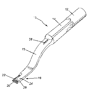
A tool bit for removing orthodontic brackets includes a handpiece-engaging portion, a shaft portion, a curved portion and a working end portion. The curved portion provides sufficient offset to present the end portion in a substantially co-planar relationship with a tooth surface. The working end portion includes at least one beveled cutting surface for cutting away the adhesive and at least one blunt/flat polishing surface for polishing away any residual adhesive that may remain after the bracket has been removed. The tool bit may also include a cooling fluid delivery port. Edges of the beveled surfaces may be serrated. Beveled surfaces and the top surface may be coated with an abrasive material such as diamond grit. These cutting surfaces are used to cut through the adhesive layer bonding the bracket to the tooth. The tool has a blunt/flat second edge surface for polishing away any remaining adhesive after removal of the bracket.


French Abstract

Un outil conçu pour détacher les fixations orthodontiques comprenant une pièce à main, une tige, une portion courbée et une portion de travail. La portion courbée offre une inclinaison suffisante pour présenter la portion d'extrémité dans une relation essentiellement coplanaire avec la surface de la dent. L'extrémité de travail comprend au moins une surface de coupe en biseau pour couper l'adhésif et au moins une surface arrondie pour polir les résidus d'adhésif qui pourraient demeurer après le retrait de la fixation. L'embout d'outil peut également comprendre un orifice de distribution de liquide de refroidissement. Les rebords des surfaces en biseau peuvent être acérés. Les surfaces en biseau et la surface supérieure peuvent être revêtues d'un matériau abrasif, comme le grain de diamant. Ces surfaces de coupe sont utilisées pour couper la couche d'adhésif liant la fixation à la dent. L'outil possède une deuxième surface arrondie/plate utilisée pour polir l'adhésif restant après le retrait de la fixation.

Claims

Note: Claims are shown in the official language in which they were submitted.


Claims:
1. A tool bit for removing orthodontic brackets, the tool bit comprising:
a handpiece-engaging portion;
a curved portion connected to the handpiece-engaging portion; and
a working end portion connected to the curved portion, the working end portion
having:
at least one beveled cutting surface for cutting an adhesive that bonds the
orthodontic
brackets to respective teeth; and
at least one blunt surface for polishing away any residual adhesive that
remains after the
orthodontic brackets have been removed.
2. The tool bit as claimed in claim 1 comprising a front beveled cutting
surface and a side
beveled cutting surface.
3. The tool bit as claimed in claim 2 wherein the front beveled cutting
surface has a serrated
front edge and wherein the side beveled cutting surface has a serrated side
edge.
4. The tool bit as claimed in claim 2 or 3 wherein the front and side beveled
cutting surfaces
are coated with an abrasive material.
5. The tool bit as claimed in claim 2 or 3 wherein the front and side beveled
cutting surfaces
are coated with diamond grit.
6. The tool bit as claimed in any one of claims 1 to 5 wherein the working end
portion
includes an upper surface that is coated with abrasive material.
7. The tool bit as claimed in any one of claims 1 to 6 comprising a
biocompatible cooling
fluid delivery port.
8. An orthodontic debonding tool comprising:
an ultrasonic handpiece; and
8

a tool bit connected to the ultrasonic handpiece, the tool bit having:
a curved portion connected to the handpiece-engaging portion; and
a working end portion connected to the curved portion, the working end portion
having:
at least one beveled cutting surface for cutting an adhesive that bonds the
orthodontic brackets to respective teeth; and
at least one blunt surface for polishing away any residual adhesive that
remains after the orthodontic brackets have been removed.
9. The orthodontic debonding tool as claimed in claim 8 wherein the tool bit
comprises a
biocompatible cooling fluid delivery port.
10. The orthodontic debonding tool as claimed in claim 8 further comprising a
biocompatible
cooling fluid delivery system attached to the tool bit.
11. The orthodontic debonding tool as claimed in any one of claims 8 to 10
wherein the tool
bit comprises a front beveled cutting surface and a side beveled cutting
surface.
12. The orthodontic debonding tool as claimed in claim 11 wherein the front
beveled cutting
surface and the side beveled cutting surface each have serrated edges.
13. The orthodontic debonding tool as claimed in claim 11 or 12 wherein the
front and side
beveled cutting surfaces are coated with an abrasive material.
14. A method for debonding orthodontic brackets that are bonded to teeth with
an adhesive,
the method comprising:
connecting a tool bit to an ultrasonic handpiece;
ultrasonically vibrating the tool bit;
cutting the adhesive using a cutting surface of the tool bit to remove the
brackets; and
9

polishing away any remaining adhesive using a blunt surface of the tool bit.
15. The method as claimed in claim 14 comprising cooling the tool bit with a
biocompatible
cooling fluid delivered internally through a fluid delivery port in the tool
bit.
16. The method as claimed in claim 14 comprising cooling the tool bit with a
biocompatible
cooling fluid delivered externally through a fluid delivery system attached to
the tool bit.
17. The method as claimed in any one of claims 14 to 16 wherein cutting the
adhesive
comprises abrading the adhesive with an abrasive-coated cutting edge.
18. The method as claimed in any one of claims 14 to 16 wherein cutting the
adhesive
comprises abrading the adhesive with an abrasive-coated serrated cutting edge.
19. A tool bit for dentistry, the tool bit comprising:
a handpiece-engaging portion;
a curved portion connected to the handpiece-engaging portion; and
a working end portion connected to the curved portion, the working end portion
having:
at least one beveled cutting surface for cutting an adhesive; and
at least one blunt surface with abrasive for polishing away any residual
adhesive.
20. A tool bit for dentistry, the tool bit comprising:
a handpiece-engaging portion;
a curved portion connected to the handpiece-engaging portion; and
a working end portion connected to the curved portion, the working end portion
having:
at least one beveled cutting surface for cutting an adhesive; and
at least one blunt surface without abrasive for polishing away any residual
adhesive.

Description

Note: Descriptions are shown in the official language in which they were submitted.


CA 02720442 2010-11-09
ORTHODONTIC DEBONDING TOOL, TOOL INSERT AND METHOD FOR
REMOVING ORTHODONTIC BRACKETS
Technical Field
[0001] The present invention relates generally to dentistry and, in
particular, to
techniques and devices for removal of orthodontic brackets.
Background
[0002] Debonding pliers, manual tools currently in practice, are available for
the removal
of orthodontic brackets. When the material of the brackets was only metal,
there was sufficient
structural integrity in the bracket to withstand a torque that these
traditional tools applied in order
to shear the adhesive bond between the bracket and the tooth.
[0003] With the introduction of ceramic, plastic, ICE, and other more fragile
materials
for orthodontic brackets, these manual tools requiring torque, proved
problematic.
[0004] There are some solutions proposed in the literature to deal with these
types of
orthodontic brackets. For example, an article by Krell, KV, Courey, JM &
Bishara, SE, 1993
`Orthodontic bracket removal using conventional and ultrasonic debonding
techniques, enamel
loss, and time requirements", American Journal of Orthodontics and Dentofacial
Othopedics,
vol. 108, no.3., pp. 262-266, discusses the use of the already existing, plain
ultrasonic chisels.
However, the use of these instruments raises concerns about possible damage to
tooth surfaces as
well as fracture of the brackets.
[0005] Embodiments disclosed herein provide a tool, tool insert and method for
removing orthodontic brackets that obviate or mitigate at least some of the
aforementioned
disadvantages.
Summary
[0006] The present invention provides an orthodontic debonding tool, tool bit
(or tool
insert) for said tool, and a related method of debonding orthodontic brackets.
This invention
constitutes an innovative solution to the problem of removing orthodontic
brackets and the
1

CA 02720442 2010-11-09
0
related problem of removing excess adhesive from the teeth without damaging
the enamel of the
teeth while also reducing chair-side time.
[0007] In accordance with an aspect of the present invention, a tool bit (or
tool insert) for
removing orthodontic brackets comprises a handpiece-engaging portion (or
handpiece-interface
portion), a curved portion connected to the handpiece-engaging portion, and a
working end
connected to the curved portion. The working end has at least one beveled
cutting surface for
cutting an adhesive that bonds the orthodontic brackets to respective teeth
and at least one blunt
or flat polishing surface for polishing away any residual adhesive that
remains after the
orthodontic brackets have been removed. Cutting surfaces and the blunt
polishing surface may
be coated with abrasive material such as diamond grit. Edges of the beveled
cutting surfaces
may be serrated.
[0008] In accordance with another aspect of the present invention, an
orthodontic
debonding tool comprises an ultrasonic handpiece, e.g. a piezoelectric
handpiece, and a tool bit
connected to the ultrasonic handpiece. The tool bit includes a curved portion
connected to the
handpiece-engaging portion, and a working end portion connected to the curved
portion. The
working end portion includes a front edge having a first beveled surface and a
first side edge
having a second beveled surface.
[0009] In accordance with yet another aspect of the present invention, a
method for
debonding orthodontic brackets that are bonded to teeth with an adhesive
entails connecting a
tool bit to an ultrasonic handpiece, ultrasonically vibrating the tool bit,
cutting the adhesive using
a cutting surface of the tool bit to remove the brackets, and polishing away
any remaining
adhesive using a flat or blunt surface of the tool bit.
[0010] Other aspects of the invention will become apparent with reference to
the
following description and drawings.
Brief Description of the Drawings
[0011] The present invention will be further understood from the following
detailed
description with reference to the drawings in which:
2

CA 02720442 2010-11-09
[0012] Figure 1 is a perspective view of a tool bit for removing orthodontic
brackets in
accordance with an embodiment of the present invention;
[0013] Figure 2 is a top plan view of the tool bit shown in Figure 1;
[0014] Figure 3 is a side elevation view of the tool bit shown in Figure 1;
[0015] Figure 4 is a cross-sectional view of the tool bit shown in Figure 1;
[0016] Figure 5 is a frontal elevation view of the tool bit shown in Figure 1;
[0017] Figure 6 is a partial top plan view of the end portion of the tool bit
shown in
Figure 2;
[0018] Figure 7 is a bottom plan view of the tool bit shown in Figure 1; and
[0019] Figure 8 is a partial bottom plan view of the end portion of the tool
bit shown in
Figure 7.
Detailed Description of Embodiments
[0020] Figures 1 to 5 illustrate a novel tool bit for removing orthodontic
brackets in
accordance with an embodiment of the present invention. The tool bit 10, which
is also referred
to herein as a "tool tip", "tool insert" or simply "insert", includes a
handpiece-engaging portion
12, a shaft portion 14, a curved portion 16, and a working end portion 18. The
handpiece-
engaging portion 12 may be connected to the handpiece by threads, quick-
connect or any other
suitable means of mechanical connection. The curved portion 16 provides
sufficient offset to
present the end portion in a substantially co-planar relationship with a tooth
surface. The
working end portion 18 (or "shank") has at least one cutting surface for
cutting or abrading away
adhesive that bonds the bracket to the tooth and at least one polishing
surface for polishing away
3

= CA 02720442 2010-11-09
any residual adhesive that may remain after the bracket has been removed. In
the particular
embodiment depicted in these figures, the working end portion 18 includes a
number of cutting
edges or cutting surfaces designed to cut away the adhesive that bonds the
orthodontic brackets
to the surface of the teeth. In the preferred embodiment depicted in the
figures, the working end
portion 18 includes a front edge 20, a first side edge 22, a top (upper)
surface 24, and a second
side edge 26. The front edge 20 and the first side edge 22 are designed to cut
and abrade the
adhesive. The second side edge 26 is a blunt surface designed to polish the
tooth to remove any
remaining adhesive after the bracket has been detached from the tooth.
[00211 As shown in these figures, the tool bit also includes a cooling fluid
delivery port
28 (i.e. a cooling fluid delivery conduit) for conveying water (or any other
biocompatible cooling
fluid) as part of a cooling fluid delivery system. The cooling fluid delivery
port (conduit) directs
cooling fluid (e.g. water) onto the cutting surfaces/edges of the working end
of the tool bit to
cool and clean the working end of the tool bit during operation.
[00221 Referring to Figure 6, the working end portion 18 is shown in greater
detail. In a
preferred embodiment, the tool bit 10 includes a front beveled cutting surface
32 and a side
beveled cutting surface 34. These surfaces may be coated with an abrasive
particle such as
diamond grit. The front beveled cutting surface 32 may have, as shown, a
serrated front edge 20.
The side beveled cutting surface 34 may also have a serrated side edge 22. The
front edge 20
and the first side edge 22 are the edges of abrasive-coated beveled surfaces
32 and 34,
respectively. As shown by way of example in Figure 6, these surfaces 32 and 34
have serrated
edges. In preferred embodiments, beveled surfaces 32 and 34 and the top
(upper) surface 24 are
coated with an abrasive material such as, for example, diamond grit, tungsten
carbide particles or
any other hard abrasive particle. Abrasive beveled surfaces 32 and 34 provide
for abrasive
cutting, i.e. by abrasion. In a preferred embodiment, the abrasive material
includes diamond grit.
A diamond particle size of 40 microns (i.e. a grit mesh size of 400) is
believed to work well,
although diamond grit of other particle sizes may be utilized. In the
preferred embodiment, the
second side edge 26 (which is not serrated in the illustrated embodiment) is
also coated with an
abrasive material such as diamond grit (although in other embodiments, it need
not be coated
with an abrasive).
4

= CA 02720442 2010-11-09
[0023] Referring to Figures 7 and 8, there is illustrated in a bottom plan
view and partial
view the tool bit of Figures 1 to 6. Figures 7 and 8 show a flat and smooth
undersurface 30 with
adjacent serrated, abrasive-coated, beveled surfaces 36 and 38. The smooth
flat undersurface 30
is masked during the abrasive coating process so no abrasive material is
adhered to this
undersurface 30. The undersurface 30 is made smooth to avoid damaging the
enamel of the
tooth when the tool is used to pry the orthodontic bracket from the tooth. In
other words, this
undersurface 30 provides relief to a tooth surface from abrasive beveled
surfaces 36 and 38 used
to remove the adhesive layer bonding the bracket to the tooth. Thus, the tooth
surface (enamel)
is safely distanced from the abrasive surfaces.
[0024] In operation, the tool bit 10 is inserted into a handpiece of an
ultrasonic unit. The
ultrasonic unit transmits vibrations through the handpiece to the tool bit 10
to facilitate a cutting
action at the front and first side edges 20 and 22. Abrasive beveled edges 32,
34, 36 and 38 wear
away the adhesive layer bonding the bracket to the tooth, while the smooth
undersurface 30
ensures that the tooth enamel is protected from the abrasive surfaces. The
blunt side surface 26
(which may or may not be coated with an abrasive) may be used for polishing
the tooth to
remove any remaining adhesive from the surface of the tooth after the
orthodontic bracket has
been removed. The combination of the two sets of serrated edges 32 and 34
together with 36 and
38 provide a fine edge for entry into the adhesive layer.
[0025] The tool bit 10 may be made of surgical stainless steel (e.g. stainless
steel 316L).
Alternatively, the tool bit 10 may be made of titanium or any other suitable
material that is
capable of transmitting the ultrasonic vibrations from the handpiece to the
working end 18 of the
tool bit 10. The handpiece-engaging portion 12 (i.e. handpiece-interfacing
portion) may be
adapted to fit any type of handpiece. The fluid delivery port may also be
eliminated where an
external fluid delivery system can be attached to the tool bit and/or
handpiece.
[0026] In the preferred embodiment, the cutting surfaces/edges 20, 22 are
serrated. As
shown in the Figure 6, these serrations may be parallel to a longitudinal axis
of the shank 18 of
the tool bit 10. This "rake angle" (i.e. the angle between the serrations and
the longitudinal axis)
in the illustrated embodiment is thus zero (since the forward-facing
serrations are parallel to the
longitudinal axis). The rake angle may be varied to achieve other effects.
5

= CA 02720442 2010-11-09
[00271 Furthermore, the number of serrations may be varied from what is
depicted by
way of example in the figures.
[00281 In another embodiment, the tool bit 10 may also be constructed without
any
serrations at all. In that case, all cutting action is performed by the
abrasive particles. In such
an embodiment, the abrasive grit size may be varied (e.g. increased).
Furthermore, in another
embodiment, the tool bit may have only a subset of the serrated edges that are
shown in the
preferred embodiment, e.g. only the front edge 20 or only the first side edge
22.
[00291 In another embodiment, the "shank angle", i.e. the angle of the shank
18 relative
to the handpiece-engaging portion 12 and the shaft portion 14, may also be
varied. In the
illustrated embodiment, the shank angle is zero since the shank is parallel to
the handpiece-
engaging portion 12 and the shaft portion 14. Other angles may be desirable
for achieving
different effects.
[00301 It should also be appreciated that the lengths and widths of the
handpiece-
engaging portion 12, shaft portion 14, and working end portion (shank) 18, as
well as their
respective ratios, may all be varied.
[00311 A right-handed tool bit is depicted in the drawings. As shown, the
serrated edge
22 runs along the right side of the tool bit 10. A left-handed tool bit may be
constructed with a
serrated edge along the left side of the tool bit (for left-handed dentists).
[00321 Another aspect of the invention is a novel orthodontic debonding tool
incorporating the novel tool bit described above. The debonding tool includes
an ultrasonic
handpiece for ultrasonic vibration of the novel tool bit. The novel tool bit
comprises (as
described above), the tool-engaging portion, shaft portion, and working end.
As noted above, the
working end, or shank, includes one or more cutting surfaces and/or edges that
cut away the
adhesive to detach the brackets from the teeth. These cutting surfaces/edges
may be abrasive-
coated and/or serrated, as described above. At least one surface of the tool
bit is a polishing
surface. In the preferred embodiment, as depicted in the drawings, the flat
smooth bottom
surface 30 protects the adjacent enamel of the tooth when the tool is used to
pry an orthodontic
bracket from the tooth.
6

CA 02720442 2010-11-09
[0033] Yet another aspect of the invention is a novel method of debonding
orthodontic
brackets using the novel tool bit described above. This method entails
connecting a tool bit to an
ultrasonic handpiece and then ultrasonically vibrating the tool bit
(activating the handpiece or an
ultrasonic unit connected to the handpiece). This causes the tool bit to
oscillate at an ultrasonic
frequency. Optionally, the frequency may be controlled using a controller. The
method then
entails cutting adhesive (that bonds the orthodontic brackets to the teeth)
using one or more
cutting surfaces and/or cutting edges of the tool bit to thereby remove the
brackets. Once the
brackets have been removed, there will usually be some residual adhesive on
the teeth. The
method thus entails a further step of polishing away any remaining adhesive
using a smooth
surface of the same tool bit. Thus, the invention provides a single tool bit
that can be used to
both remove (detach) the bracket and also polish the tooth. This invention not
only reduces the
likelihood of a bracket breaking during removal but also reduces the total
time required to
remove the brackets from the teeth. As will be appreciated, the quicker and
more effective
bracket removal is highly advantageous to both dentist and patient alike.
[0034] The foregoing embodiments are presented by way of example to illustrate
particular ways of implementing this invention. Persons of ordinary skill in
the art having read
this disclosure will recognize that numerous modifications, refinements,
variations, alterations
and adaptations may be made to the particular embodiments described above
without departing
from the scope and spirit of the inventive concepts presented in the present
specification. The
scope of the exclusive right sought by the Applicant is therefore intended to
be defined solely by
the claims.
7

Representative Drawing
A single figure which represents the drawing illustrating the invention.
Administrative Status

2024-08-01:As part of the Next Generation Patents (NGP) transition, the Canadian Patents Database (CPD) now contains a more detailed Event History, which replicates the Event Log of our new back-office solution.

Please note that "Inactive:" events refers to events no longer in use in our new back-office solution.

For a clearer understanding of the status of the application/patent presented on this page, the site Disclaimer , as well as the definitions for Patent , Event History , Maintenance Fee  and Payment History  should be consulted.

Event History

Description Date
Inactive: Office letter 2021-02-05
Inactive: Correspondence - MF 2020-06-30
Inactive: Office letter 2020-06-04
Inactive: Correspondence - MF 2020-05-22
Reinstatement Request Received 2020-05-15
Reinstatement Request Received 2020-05-14
Maintenance Request Received 2020-05-14
Time Limit for Reversal Expired 2019-11-12
Common Representative Appointed 2019-10-30
Letter Sent 2018-11-09
Change of Address or Method of Correspondence Request Received 2018-01-10
Maintenance Request Received 2017-09-29
Maintenance Request Received 2016-10-31
Maintenance Request Received 2015-10-29
Inactive: Payment - Insufficient fee 2015-10-22
Maintenance Request Received 2015-10-08
Maintenance Request Received 2014-10-16
Grant by Issuance 2013-03-19
Inactive: Cover page published 2013-03-18
Pre-grant 2013-01-08
Inactive: Final fee received 2013-01-08
Notice of Allowance is Issued 2012-09-14
Letter Sent 2012-09-14
Inactive: Approved for allowance (AFA) 2012-09-12
Amendment Received - Voluntary Amendment 2012-08-15
Inactive: S.30(2) Rules - Examiner requisition 2012-07-05
Letter sent 2012-05-16
Advanced Examination Determined Compliant - paragraph 84(1)(a) of the Patent Rules 2012-05-16
Application Published (Open to Public Inspection) 2012-05-09
Inactive: Cover page published 2012-05-08
Inactive: Office letter 2012-03-26
Letter Sent 2012-03-26
Inactive: Advanced examination (SO) 2012-03-21
Request for Examination Requirements Determined Compliant 2012-03-21
Inactive: Advanced examination (SO) fee processed 2012-03-21
All Requirements for Examination Determined Compliant 2012-03-21
Early Laid Open Requested 2012-03-21
Request for Examination Received 2012-03-21
Inactive: IPC assigned 2011-02-23
Inactive: First IPC assigned 2011-02-23
Inactive: IPC assigned 2011-02-23
Inactive: Filing certificate - No RFE (English) 2010-12-02
Application Received - Regular National 2010-11-29
Letter Sent 2010-11-29
Inactive: Filing certificate - No RFE (English) 2010-11-29
Small Entity Declaration Determined Compliant 2010-11-09

Abandonment History

Abandonment Date Reason Reinstatement Date
2020-05-15
2020-05-14

Maintenance Fee

The last payment was received on 2012-10-26

Note : If the full payment has not been received on or before the date indicated, a further fee may be required which may be one of the following

  • the reinstatement fee;
  • the late payment fee; or
  • additional fee to reverse deemed expiry.

Patent fees are adjusted on the 1st of January every year. The amounts above are the current amounts if received by December 31 of the current year.
Please refer to the CIPO Patent Fees web page to see all current fee amounts.

Fee History

Fee Type Anniversary Year Due Date Paid Date
Application fee - small 2010-11-09
Registration of a document 2010-11-09
Request for examination - small 2012-03-21
Advanced Examination 2012-03-21
MF (application, 2nd anniv.) - small 02 2012-11-09 2012-10-26
Final fee - small 2013-01-08
MF (patent, 3rd anniv.) - small 2013-11-12 2013-10-25
MF (patent, 4th anniv.) - small 2014-11-10 2014-10-16
MF (patent, 5th anniv.) - small 2015-11-09 2015-10-08
MF (patent, 6th anniv.) - small 2016-11-09 2016-10-31
MF (patent, 7th anniv.) - standard 2017-11-09 2017-09-29
Owners on Record

Note: Records showing the ownership history in alphabetical order.

Current Owners on Record
GENEPRO SYSTEMS INC.
Past Owners on Record
CHITRA SHANMUGHAM
Past Owners that do not appear in the "Owners on Record" listing will appear in other documentation within the application.
Documents

To view selected files, please enter reCAPTCHA code :


To view images, click a link in the Document Description column. To download the documents, select one or more checkboxes in the first column and then click the "Download Selected in PDF format (Zip Archive)" or the "Download Selected as Single PDF" button.

List of published and non-published patent-specific documents on the CPD .

If you have any difficulty accessing content, you can call the Client Service Centre at 1-866-997-1936 or send them an e-mail at CIPO Client Service Centre.


Document
Description 
Date
(yyyy-mm-dd) 
Number of pages   Size of Image (KB) 
Description 2010-11-08 7 349
Drawings 2010-11-08 2 37
Abstract 2010-11-08 1 23
Claims 2010-11-08 3 88
Representative drawing 2011-11-06 1 6
Claims 2012-08-14 3 105
Courtesy - Certificate of registration (related document(s)) 2010-11-28 1 103
Filing Certificate (English) 2010-12-01 1 156
Acknowledgement of Request for Examination 2012-03-25 1 177
Reminder of maintenance fee due 2012-07-09 1 112
Commissioner's Notice - Application Found Allowable 2012-09-13 1 163
Notice of Insufficient fee payment (English) 2015-10-21 1 91
Maintenance Fee Notice 2018-12-20 1 184
Maintenance Fee Notice 2018-12-20 1 183
Correspondence 2012-03-20 2 69
Correspondence 2012-03-25 1 14
Correspondence 2013-01-07 2 54
Fees 2014-10-15 1 115
Fees 2015-10-07 1 61
Maintenance fee payment 2015-10-28 3 95
Maintenance fee payment 2016-10-30 1 131
Maintenance fee payment 2017-09-28 1 43
Reinstatement (MF) 2020-05-13 4 102
Maintenance fee payment 2020-05-13 3 62
Reinstatement (MF) 2020-05-14 4 95
Maintenance fee correspondence 2020-05-21 1 71
Courtesy - Office Letter 2020-06-03 1 177
Maintenance fee correspondence 2020-06-29 1 27
Courtesy - Office Letter 2021-02-04 2 202