Note: Descriptions are shown in the official language in which they were submitted.
CA 02720660 2010-10-05
1
COLLAR FOR ANIMALS, IN PARTICULAR DOGS
The invention relates to a collar for animals, in particular for dogs,
comprising
chain links, wherein the chain links each have a hook portion and each a hook-
in portion which can be fitted into one another. The chain link can, but does
not
have to, have at least one tooth protruding inwardly.
A collar for animals is known from DE 84 15 418 U1 in which the individual
chain links are made from round stock and are additionally encased, for
example with leather. The free ends of each section of the round stock, from
which one chain link, respectively, is bent, form two teeth. The lining is
supposed to prevent the spiked collar from being recognized as such
immediately.
The dog collar known from DE 9 41 458 A, which, however, comprises only two
chain links that are bent from round stock and have two teeth each, uses
similar
chain links.
In the case of spiked collars, efforts are being taken to approximate the
collar to
a normal collar, as far as possible, in order for it not to be immediately
recognized as a spiked collar. In this respect, spiked collars whose chain
links
are made from round stock are disadvantageous because they are clearly
distinct from other collars. However, such collars have numerous advantages;
they can be separated at any time between two chain links, they can be
produced simply, they are very well protected against wear and tear and are
easy to keep clean.
Based on the known collars, the invention has set itself the object of
developing
the known collars further in such a way that they make a good visual
impression; in any case resemble a normal collar more closely than a typical
CA 02720660 2010-10-05
2
collar, i.e. one that has been made of wire.
This object is achieved by a collar for animals, in particular for dogs,
comprising
chain links which are each produced from a sheet-metal blank and by bending
this sheet-metal blank about bending lines, wherein the chain links each have
a
hook portion and each a hook-in portion, and wherein the hook-in portion
comprises a window.
In this collar, the individual chain links are produced from a sheet-metal
blank.
The chain links are preferably produced from metal. The outward appearance of
the collar is that of a link chain consisting of full-surface sheet-metal
plates lying
next to one another. It can virtually not be recognized as a spiked collar.
The
spikes can be disposed on the inside in such a concealed manner that they
cannot be recognized immediately even if one looked behind the collar
obliquely. It is also advantageous that the spikes can be configured
independently from the geometry of the chain links and without regard to the
function of the chain links. They are mere additions and could thus be omitted
without the chain losing its purchase. Where the bent-wire spike collars
according to the prior art, as they are generally prevalent, are concerned,
this is
not the case.
What is retained in this invention is the high wear-resistance of the pure
metal
chains. Cleaning is also convenient; the chain can be cleaned easily.
Visually,
the chain according to the invention is more attractive and beautiful than the
collars according to the prior art.
Preferably, the window is dimensioned such that the hook portion fits through
the window, and the hook-in portion moreover comprises an edge portion
located between the window and the rear end of the chain link, and the hook
portion has a free opening dimensioned such that the edge portion fits through
CA 02720660 2010-10-05
3
the free opening.
In contrast to the collars made from wire, the chain links are not elastically
deformed during dismantling and assembling; rather, joining and dismantling
requires a complicated path similar to a chicane. This results in a lock by
positive fit, and not an elastic lock, as is the case in the collars made from
wire.
However, this means that mishandling is largely precluded, that the individual
chain links can be manufactured from a relatively solid material, and that the
shape of the individual chain links does not change even over an extended
period of time.
In order to separate and dismantle two adjacent chain links, the hook portion
in
each case has to be guided through the window. The hook portion has a
complicated shape; in any case, it does not run in a straight line but is
curved,
mostly curved several times, for example, it extends in an S-shaped curve.
This
may also include the at least one tooth protruding transversely from the chain
link. A complicated movement is thus required in order to separate or join the
chain links. This movement is simple with regard to two adjacent chain links;
however, in the normal sequence of movements it practically cannot occur
since there is a certain tension in the chain if the chain is worn, and a
spontaneous separation can be excluded in this case.
Preferably, the tooth area comprises two teeth that extend parallel to one
another and are configured similar to a dog's teeth. The invention makes it
possible to select any shape for the teeth. Thus, they can be shaped so as to
have an optimum effect on the dog. They can be rounded off so as to cause
practically no injuries.
It was found to be particularly preferred that the hook-in portion has an edge
portion provided between the window of the hook-in portion and the adjacent
CA 02720660 2010-10-05
4
end. This edge portion is bent at a certain angle relative to a rear main
portion
of the hook-in portion. The chain is thus rounded; the individual chain links
are
at the same angle relative to one another by which the edge portion is bent.
The
chain can thus be adapted to a certain diameter corresponding to the diameter
of the neck of the dog, and in this case has its optimum effect.
The chain links can be very easily produced in each case from a sheet-metal
blank. Metal-sheet material with typically 1 to 2 mm wall thickness is used;
preferably, the wall thickness is in the range of from 1.5 mm plus/minus 10%.
This leaves sufficient space for the relative movement of the chain links. The
individual blanks are substantially elongate; on one end, they form a tooth,
the
window is at the other end. They are bent several times into their final shape
along bending lines that extend parallel to the longitudinal direction of the
window. Machines can be used for this purpose.
Preferably, the hook portion has an inner space of the hook; this inner space
offers sufficient room for the edge portion. Preferably, the clear dimensions
of
the inner space are greater than 1.5 times the measured width of the window
(measured transverse relative to the longitudinal direction of the window). In
the
configuration which is easy to dismantle and assemble, the inner space in the
area of the free opening of the hook portion is narrow and widens towards the
outside and towards the inside. This leaves enough space for joining. The free
opening can be selected such that the edge portion, oriented obliquely, just
fits
through. This results in a good safeguard against spontaneous disengagement.
In the configuration that cannot be dismantled or assembled, the free opening
is
so small, in particular zero, that the edge portion does not fit through the
free
opening without deformation.
It was found to be preferred to provide an intermediate link in the collar. It
has
no teeth. It can be positioned in the area of the larynx of the dog. This
critical
CA 02720660 2010-10-05
area is thus protected. The intermediate link is advantageous in that the
chain
links can be disposed on both sides in a mirror-image arrangement, which
simplifies the production of the collar and, in particular, simplifies the
configuration of the final links. They can now be constructionally identical.
5
Other advantages and features of the invention become apparent from the
other claims as well as from the following description of three exemplary
embodiments of the invention, which are to be understood not to be limiting
and
which will be explained below with reference to the drawing. In the drawings:
Fig. 1: shows a side view of two chain links hooked into each other,
Fig. 2: shows a frontal view of the right chain link according to Figure 1 in
the viewing direction II,
Fig. 3: shows a top view onto a sheet-metal blank for a chain link
according to Figure 1,
Fig. 4: shows a top view onto a sheet-metal blank for an intermediate
link,
Fig. 5: shows a top view onto a sheet-metal blank for a final link,
Fig. 6: shows a side view of a collar with chain links as in Fig. 1,
Fig. 7: shows a top view onto a sheet-metal blank for a chain link for a
second embodiment,
Fig. 8: shows a side view of a chain link for the second embodiment,
Fig. 9: shows a top view onto a chain,
Fig. 10: shows a side view of two chain links hooked into each other of a
third exemplary embodiment,
Fig. 11: shows a top view onto a sheet-metal blank for a chain link
according to the third exemplary embodiment,
Fig. 12: shows a top view onto a sheet-metal blank for a final link
according to the third exemplary embodiment,
Fig. 13: shows a top view onto a sheet-metal blank for a chain link
CA 02720660 2010-10-05
6
according to the fourth exemplary embodiment, and
Fig. 14: shows a side view of a chain link for the fourth embodiment.
Figures 1 to 6 relate to a first exemplary embodiment; in this case, a simple
separation of adjacent chain links is possible without any auxiliary tools.
Figures
7 and 8 relate to a second embodiment designed such that no separation of
adjacent chain links is possible without plastic deformation. Figure 9 applies
to
all embodiments. Figures 10 to 12 relate to a third embodiment; no teeth are
provided. Figures 13 and 14 relate to a fourth embodiment, which also does not
comprise any teeth. The exemplary embodiments two to four are only described
to the extent they differ from the first one.
The collar according to the first exemplary embodiment comprises normal chain
links 20, an intermediate link 22 and two final links 24, all of which are
respectively produced from a sheet-metal blank. The normal chain links 20 will
be first discussed below. They are produced from a sheet-metal blank as shown
in Fig. 3. It is produced from a metal, preferably stainless steel, for
example by
stamping or cutting; it typically has a material thickness of approximately
1.5
mm. The material is selected such that it practically cannot be bent manually.
Starting with the sheet-metal blank as shown in Fig. 3, several bending
operations are carried out about a total of six bending lines 26 to 36; in
addition,
an area 38 lying between the second bending line 28 and the third bending line
is curved.
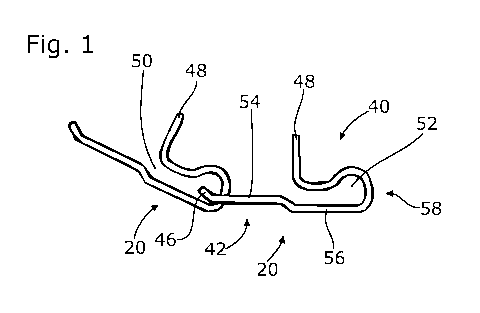
The chain links 20 each comprise a hook portion 40 and a hook-in portion 42.
The fourth and fifth bending lines 32, 34 form the boundary between these two
areas 40, 42. Seen in the longitudinal direction of the sheet-metal blank
according to Figure 3, these two areas 40, 42 have a ratio of approximately
2:1.
Moreover, they differ with respect to the dimension in the transverse
direction,
CA 02720660 2010-10-05
7
that is, the width. The hook-in portion 42 has a constant width approximately
corresponding to its length. The hook portion 40 has two different width
dimensions. Over a substantial part of its total length, it has a smaller
constant
width, which is about 2/3 the size of the width of the hook-in portion 42;
towards
the hook-in portion 42, it widens in steps near the third bending line 30 to
have
the width of the hook-in portion 42. The blank according to Figure 3 is mirror-
symmetrical about a center line extending parallel to the longitudinal axis.
This
mirror symmetry also applies to all other sheet-metal blanks shown, that is,
Figure 4, Figure 5 and Figure 7.
In the hook-in portion 42, a window 44 is provided; it extends transversely to
the
longitudinal direction of the blank. Its dimensions are selected such that the
hook portion 40 fits through the window 44. Whether this happens with more or
less clearance is a matter for adjustment. The oversize of the window 44
relative to the cross-sectional dimension of the hook portion 40 can be 5 to
100%.
The hook-in portion 42 furthermore comprises an edge portion 46 located
between the window 44 and a rear end of the chain link 20. At the opposite
end,
the sheet-metal blank has a first end portion; there, it has two teeth 48.
They
are arranged like a W. They lie in the same plane. As Figure 2 shows, the
teeth
48 have a vertex angle of 340; there is a free angular area of 25 between the
two teeth 48. The teeth 48 have a free length of 8 mm. They are rounded off
with a rounded portion of about 1.2 mm; preferably, the rounding-off circle
has a
radius if 0.8 to 2 mm. As can be seen in particular in the blank according to
Figure 3, the tooth 48 is part of the hook portion 40.
During the production of the chain link 20, a number of bending operations are
carried out, starting from the flat sheet-metal blank according to Figure 3,
which
can be carried out in any order. They are described below in an arbitrary
order:
CA 02720660 2010-10-05
8
The edge portion 46 is bent in an angle of about 30 to 400 about the sixth
bending line 36; in this case, bending is done in the mathematically positive
direction. The fifth bending line 34 and the fourth bending line 32 are close
to
each other, the distance is a few millimeters; in this case, a cranking
operation,
i.e. a parallel offset, is carried out. In the process, bending is carried out
in the
mathematically negative direction about the fifth bending line 34, and in the
mathematically positive direction about the fourth bending line 32. A bending
operation of about 900 is carried out about the third bending line 30 in the
mathematically positive direction. The area 38 located between the third
bending line 30 and the second bending line 28 is now continuously bent in the
same direction and then forms a curved front area 58. The second bending line
28 has a bend by about 450 in the mathematically positive direction. A 90
bending operation is also carried out in the mathematically positive direction
in
the area of the first bending line 26. The final link 24 is also bent in the
same
way, preferably in the same device.
As is apparent from Figure 1, the hook portion 40 comprises a free opening 50
which is a part of the inner space 52 of the hook portion 40. This free
opening
50 is the narrow section; starting therefrom, the inner space 52 opens into an
area of significantly larger cross-sectional dimensions.
In order to separate the two chain links 20 shown in Figure 1, the right chain
link
20 is rotated, first in the counter-clockwise direction, the left chain link
is held
fast. By further movement to and fro, the hook portion 40 is threaded out of
the
window 44. In the final step, the window 44 is pulled over the two teeth 48.
Correspondingly, assembly is carried out in reverse. The dimensions of the
edge portion 46 and the free opening 50 are designed such that the edge
portion 46 fits through the free opening 50.
The edge portion 46 is bent about the sixth bending line 36 because the normal
i
CA 02720660 2010-10-05
9
shape of the collar is supposed to be a circular shape as it is shown in
Figure 6.
The edge portions 46 are kinked in at least about the same angle in which two
chain links 20 are angled relative to each other in the normal position, as
Figure
6 shows. The angle is even selected to be slightly greater, for example by 5
to
200 greater than a tangent angle.
The hook-in portion 42 comprises a rear main portion 54, which is plane. It is
limited, among other things, by the window 44, the described crank and the
lateral edges of the blank. The hook portion 40 comprises a front main portion
56 extending between the third bending line 30 and the fourth bending line 32.
It
bears the described stepped tapering. In the area of the described crank, the
two main portions 54, 56 are parallel-offset by one material thickness of the
sheet material used. The teeth 48 are at an angle of about 90 relative to the
main portions 54, 56. The hook portion 40 comprises the curved front end
portion 58 located between the second bending line 28 and the third bending
line 30. As described, the material is continuously curved there.
The intermediate link 22 is described below. It comprises two intermediate-
link
windows 60 which extend parallel to each other and are constructionally
identical with the window 44 of every normal chain link 20. A main portion 62
is
located between these intermediate-link windows 60. It is plane. It can be
configured in any length; the length shown, that is, the distance of the
intermediate-link windows 60, is only an exemplary embodiment. An
intermediate-link portion 64 is respectively located outside of the
intermediate-
link window 60; they are also constructionally identical to the edge portion
46 of
the chain link 20. They are also bent about a sixth bending line 36
corresponding to the illustration in Figure 3, with the two intermediate-link
portions 64 being bent in different directions, as Figure 6 shows. No other
bends were made.
CA 02720660 2010-10-05
A final link 24 is described below. As shown in Figure 5, its cut largely
corresponds to the cut of the normal chain link 20. The external shape is
identical. Everything else up to the fifth bending line 34 is also designed
and
configured identically. Beyond this bending line, there is no window in the
final
5 link, but rather a large opening 66; it serves for receiving connection
loops or
the like, for example of plastic, leather, etc., and for connection with a
leash (not
shown). In the exemplary embodiment shown, the large opening 66 is circular
and has a diameter approximately corresponding to the longitudinal dimension
of the window 44. In contrast to the normal chain link 20, the sixth bending
line
10 36 may be omitted. For production reasons, however, it is advantageous to
provide it as shown. It should be emphasized that the final links 24 each also
comprise teeth 48.
The second exemplary embodiment shall now be discussed below. It differs
from the first exemplary embodiment by the free opening 50 now having the
value zero, that is, in other words, the inner space 52 of the hook portion 40
being closed on all sides. Special operations are required in order to be able
to
bring the individual chain links together. It has to be plastically deformed.
As
Figure 7 shows, the sheet-metal blank for the normal chain link 20 according
to
the second embodiment is slightly longer than the sheet-metal blank according
to Figure 3, but otherwise largely identical. The greater length is largely
reflected in a greater distance between the second bending line 28 and the
third
bending line 30. Additionally, the sheet-metal blank according to Figure 7 has
a
viewing window 68 formed in the front main portion 56. It has a transverse
dimension corresponding to the dimensions of the window 44. In the
longitudinal direction, however, it is three times as wide as the window 44.
As
Figure 8 shows, the hook web is curved in such a way that it partially lies in
the
area of the viewing window 68 and fills it. Thus, the finished chain link 20,
in the
area of the viewing window 68, has a thickness corresponding to a single
material thickness.
CA 02720660 2010-10-05
11
The viewing window 68 can be omitted. It is sufficient if the hook web is
brought
into contact with the front main portion 56 or close to it. The free opening
50 is
so narrow already in that case that assembly or dismantling is not possible
without plastic deformation.
The blanks for the links 20, 22, 24 have the same total width and consist of
the
same metal-sheet material.
The third exemplary embodiment substantially corresponds to the first
exemplary embodiment, but the hook portion in this case does not comprise
any teeth. Instead, there is a bent portion 70. This can also be described as
follows: the material forming the teeth 48 according to the first embodiment
is
reduced only to the extent that there is just a bent portion 70 which is at
most
20 %, in particular 10 % as long as a tooth. As the fourth exemplary
embodiment will show, such a bent portion 70 can also be dispensed with
completely. There is the option of bending the bent portion 70 in another
direction, e.g. also in the opposite direction, so that it protrudes into the
free
opening 50. As Figures 11 and 12 show, the blanks are now significantly
shorter as compared with Figures 3 and 5.
The fourth exemplary embodiment corresponds to the second exemplary
embodiment, but again without any teeth. In contrast to the third exemplary
embodiment, no bent portion 70 is provided. Thus, the blanks for the
individual
links end at the first bending line 26. The first bending line 26 is omitted.
The
blanks thus become even shorter.
The top view onto the chain according to Fig. 9 applies to all four exemplary
embodiments. This view shows that it is not recognizable from the outside
whether teeth 48 are present or not.
CA 02720660 2010-10-05
12
The combination of individual features from the claims and/or the description
with each other, thus describing the invention, is reserved.