Note: Descriptions are shown in the official language in which they were submitted.
CA 02720696 2010-10-01
WO 2009/124104 PCT/US2009/039073
NON-WOVEN MATERIAL AND METHOD OF MAKING SUCH MATERIAL
FIELD
[0001] The field relates to a non-woven material as well as a method of its
manufacture, and more particularly, a non-woven material effective to provide
sound
absorption suitable for use as an acoustic ceiling tile.
BACKGROUND
[0002] A typical acoustic ceiling tile is a non-woven structure including a
core
manufactured from base fibers, fillers, and binders. The base fibers are
usually
mineral wool or glass fibers. The fillers are commonly perlite, clay, calcium
carbonate,
or cellulose fibers. The binder is typically cellulose fibers, starch, latex,
or similar
materials. Upon drying, the binder forms bonds with the other materials to
form a
fibrous network that provides structural rigidity to the core. To be used as a
typical
ceiling tile, the core should be substantially flat and self-supporting in
order to be
suspended in a typical ceiling tile grid or similar structure.
[0003] For non-woven structures to be suitable for acoustical ceiling tile
applications, they generally satisfy various industry standards and building
codes
relating to fire rating and noise reduction. For example, industry standards
typically
specify ceiling tiles to have a Class A fire rating according to ASTM E84,
which
generally requires a flame spread index less than 25 and a smoke development
index
less than 50. Regarding noise reduction, industry standards typically specify
the
acoustical ceiling tile to have a noise reduction coefficient according to
ASTM C423 of
at least about 0.55.
[0004] Acoustic ceiling tiles are commonly formed via a wet-laid process
that uses
an aqueous medium to transport and form the tile components into a non-woven
mat
used to form the core of the acoustic ceiling tile. The basic process involves
first
blending the various tile ingredients into an aqueous slurry. The aqueous
slurry is
- 1 -
CA 02720696 2010-10-01
WO 2009/124104 PCT/US2009/039073
then transported to a headbox and distributed over a moving, porous wire web
to
form a uniform mat having a desired size and thickness. Water is then removed
and
the mat is dried. The dried mat may then be finished into the ceiling tile
structure by
slitting, punching, coating and/or laminating a surface finish to the tile. In
the wet-
laid process, water serves as the transport media for the various tile
ingredients. This
wet laid process is acceptable because high production speeds can be attained
and
because low cost raw materials (for example, recycled newsprint fibers,
recycled
corrugated paper, scrap polyester fibers, cotton linters, waste fabrics, and
the like) can
be used. However, using water to manufacture acoustical ceiling tile presents
a
number of shortcomings that render the process and formed product less than
desirable.
[0005] The wet-laid process uses a great deal of water to transport and
form
the components into the ceiling tile structure. The large amounts of water
must
eventually be removed from the product. Most wet processes, therefore,
accommodate water removal by one or more steps of free draining, vacuum,
compression, and/or evaporation. These process steps entail large energy
demands to
transport and remove the water. As such, the handling of large volumes of
water to
form the tile along with the subsequent removal and evaporation of the water
renders
the typical wet-laid process relatively expensive due to high equipment and
operating
costs.
[0006] It also is difficult using a wet-laid process to form an acoustical
ceiling tile
having high sound absorption properties. In a wet-laid process, the formed
ceiling
tiles tend to have a sealed surface due to the nature of the ingredients in
the wet-laid
formulation. A ceiling tile with a sealed surface generally has a less
efficient acoustical
barrier because the tile is less porous, which renders the tile less capable
of absorbing
sound. The sealed tile surface may actually reflect sounds, which is an
undesired
characteristic in an acoustical ceiling tile.
-2-
CA 02720696 2010-10-01
WO 2009/124104 PCT/US2009/039073
[0007] These undesired acoustical characteristics are believed to occur
from the
hydrophilic nature of the tile ingredients typically used in the wet-laid
process.
Cellulose fibers (for example, recycled newsprint), which are commonly used as
low
cost binder and filler in a ceiling tile, are highly hydrophilic and attract
an extensive
amount of water. Due in part to such hydrophilic components, wet-laid tiles
typically
have a high tipple moisture content (i.e., the moisture level of the board
immediately
prior to entering the drying oven or kiln) of about 65 to about 75 percent,
which
increases the demands of evaporation during drying. As a result, a high
surface
tension is generated on the tile ingredients during drying as water is removed
from
these hydrophilic components. Water, a polar molecule, imparts surface tension
to the
other components. This surface tension generally causes the tile surface to be
sealed
with a less porous structure. It is believed that the surface tension draws
elements in
the tile closer together densifying the structure and closing the tile pores
in the
process. Consequently, wet-laid produced ceiling tiles require further
processing to
perforate the tile in order to achieve acceptable noise reduction. Therefore,
while a
wet-laid process may be acceptable due to increased production speeds and the
ability
to use low cost materials, the use of water as a transport media renders the
process
and resulting product less cost effective when acoustic characteristics are
required for
the product.
[0008] In some cases, a latex binder also may be used in acoustical ceiling
tiles and
is often preferred in a wet-laid process using mineral wool as the base fiber.
Latex,
however, is generally the most expensive ingredient employed in a ceiling tile
formu-
lation; therefore, it is desired to limit the use of this relatively high cost
ingredient.
Other binders commonly employed in ceiling tiles are starch and, as described
above,
cellulose fibers. Starch and cellulose, however, are hydrophilic and tend to
attract
water during processing and generate the high surface tension problems
described
above.
- 3 -
CA 02720696 2010-10-01
WO 2009/124104 PCT/US2009/039073
[0009] Other non-woven structures, such as diapers, hygienic wipes,
filtration
media, and automotive insulation, may be formed via an air-laid process that
uses air
as the transport media for the various ingredients forming a non-woven
material. An
air-laid process eliminates the need to transport and remove water; however,
all
components in the formulation must be transportable in an air stream. As a
result,
heavy, dense, or long fibers as well as liquid components are generally not
suitable for
the air-laid process. That is, liquid resin binders and/or latex binders
commonly used
in ceiling tile manufacture generally cannot be used in the air laid process.
Typical air-
laid processes, therefore, prefer short glass fibers employed as the base
fiber (i.e.,
about 10 mm in length) together with some type of heat-fusible or thermal
bonding
fiber, such as a single component or a bi-component bonding fiber. Once formed
into
a non-woven material, the thermal bonding fiber is heated to melt a portion of
the
fiber in order to bond the base fiber structure within the desired core
structure.
[0010] WO 2006/107847 A2 discloses an air-laid process to form automobile
insulation and ceiling tile structures using bi-component thermal bonding
fibers and
synthetic or cellulose matrix fibers. In one example, the '847 publication
describes a
ceiling tile composition of 30 percent bi-component fiber and 70 percent
cellulose fiber
(fluff) that provides improved acoustical properties over commercial mineral
fiber and
glass fiber ceiling tiles. While providing improved acoustical properties, the
disclosed
ceiling tile structures of the '847 publication have the shortcoming that they
would
generally not comply with current fire code ratings specified by industry
standards for
use as a ceiling tile. With the use of 70 percent cellulose fibers in the
ceiling tile (as
well as 100 percent organic fibers), it is expected that the formed base mats
of the '847
publication would not comply with the fire code ratings of ASTM E84
requirements
for ceiling tiles due to such high levels of cellulose and organic fibers.
[0011] The '847 publication above and US 2006/0137799 A1 further suggest
that
non-woven structures can be made using air-laid processes with glass fibers
together
-4-
CA 02720696 2010-10-01
WO 2009/124104
PCT/US2009/039073
with bi-component fibers. While the glass fiber would provide enhanced fire
ratings
under industry standards, glass fibers having a short size suitable for air-
laid
processes are a more expensive raw material and have health and environmental
disadvantages relative to other raw materials. For example, glass fibers may
cause
irritation to human skin, eyes, and respiratory systems. Many organizations
consider
glass fibers as an acute physical irritant to skin, eyes, and the upper
respiratory tract.
Generally, the smaller the fiber sizes, the harsher the irritation. In some
cases, if the
exposure to glass fibers is sufficient, the fibers may produce irritation
dermatitis and
difficulty in breathing. In other cases, some studies have shown that
fiberglass when
combined with dust, dirt, and moisture can be a good medium for microbial
growth of
mold, fungus, and some bacteria.
[0012] As
noted above, mineral wool also is commonly used in acoustical ceiling
tiles to provide enhanced fire ratings because mineral wools can have melting
points
up to 2200 F, which is even higher than common glass fibers. Mineral wools are
commonly used in the wet-laid process along with starch or latex binders to
form
acoustical ceiling tiles. However, due to the abrasive nature and high shot
content of
typical mineral wools (i.e., up to about 60 percent in some cases), this raw
material is
generally not recommended for use in an air-laid process because the abrasive
nature
of the mineral wool fiber tends to be destructive to the air-laid forming
equipment and
the high shot content can plug air filtering systems to decrease the
efficiency of
vacuum suction boxes. With decreased vacuum strengths, the air-laid forming
head
has difficulty forming a uniform mat having a basis weight sufficient to
provide the
rigidity needed for ceiling tiles. As used herein, mineral wool shot generally
refers to
a by-product of the mineral wool manufacturing process comprising non-fibrous,
mineral particulate matter having diameters ranging from about 45 to about 500
microns.
- 5 -
CA 02720696 2010-10-01
WO 2009/124104 PCT/US2009/039073
[00131 The '847 publication lists glass fibers and ceramic fibers as
suitable
synthetic matrix fibers to be used in an air laid process, but specifically
does not list
mineral wool as an acceptable substitute. As generally understood, mineral
wool
fibers are considered distinct from glass fibers and ceramic fibers. Even
though all
such fibrous types are generally man-made or synthetic fibers, each has
different
characteristics and properties due to raw material sources and manufacturing
methods. Glass fibers are manufactured through an extrusion process forming a
continuous filament that is typically chopped into a desired size; as a
result, glass
fibers typically do not include an appreciable shot content. Ceramic fibers,
on the
other hand, are typically made from a spinning or blowing method with more
expensive raw materials. Ceramic fibers typically have substantially less shot
content
than mineral wool fibers.
[00141 Notwithstanding the above, however, due to the strength of the high
melting component in common bi-component fibers used in air-laid forming
processes, existing multi-component fibers also have a relatively high
strength (i.e.,
break load and elongation), which is a property desired in the products for
which this
type of fiber is commonly used (i.e., diapers, hygienic wipes, filtration
media, and
automobile insulation). However, consumers of acoustic ceiling tile expect the
tile to
be manually cuttable, such as with a common utility knife, so that an
installer can
easily cut holes in the ceiling tile for sprinklers, lights, HVAC ducts, and
the like. In
addition, it is not uncommon for a typical suspended ceiling to require
partial size tiles
for edges or corners. Because acoustic ceiling tiles generally come in
standard, fixed
sizes, the installer is often required to cut individual tiles to fit the
particular
requirements of the ceiling grid. Generally due to the high strength (i.e.,
break loads
and elongation) of commercially available bi-component fibers, forming
acoustic
ceiling tiles using existing bi-component fibers produces a tile that requires
excessive
force to cut and exhibits fiber pull out, which are properties undesired by
consumers
and installers.
- 6 -
CA 02720696 2010-10-01
WO 2009/124104 PCT/US2009/039073
[0015] In short, existing wet-laid and air-laid processes with available
ingredients
commonly used therewith cannot cost effectively produce an acceptable acoustic
ceiling tiles that meet all industry and building code standards (i.e.,
acoustic
requirements) as well as consumer expectations for acoustic ceiling tiles
(i.e.,
cutability, flatness, self supporting, and the like). Existing wet-laid
processes are
energy and capital intensive and form ceiling tiles with less desired
acoustical
properties. Air laid non-woven materials, which may be suitable for diapers,
filter
media, and automotive insulation, may be more economical to manufacture, but
existing formulations and processes are not suitable to manufacture acoustic
ceiling
tiles meeting both consumer and industry specifications. Air laid non-woven
materials formed with high amounts of cellulose and/or organic fibers
generally will
not meet industry fire rating standards for ceiling tiles, and the use of
available bi-
component fibers renders the formed material difficult to cut due to the high
strength
and elongation of these fibers. While short glass fiber can be use in ceiling
tiles and an
air-laid process, glass fibers can be cost prohibitive and have health and
environmental concerns.
[0016] Accordingly, a flat, self-supporting non-woven material comprising
bi-
component fibers and method of making thereof that is suitable under industry
standards as acoustic ceiling tile (i.e., acoustic properties) that can be
fabricated
without the energy and capital costs of a wet-laid process and that also meets
consumer expectations for cutability are desirable.
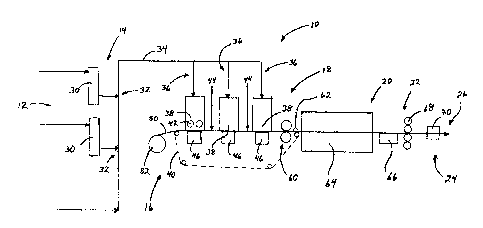
BRIEF DESCRIPTION OF THE DRAWINGS
[0017] FIG. 1 is a schematic view of an exemplary air-laid process for
forming the
non-woven materials described herein; and
[0018] FIG. 2 is a flow chart of an exemplary non-woven forming process.
- 7 -
CA 02720696 2015-02-25
DETAILED DESCRIPTION
[0019] In general, a non-woven material is provided including a blend of an
inorganic base fiber and an organic binding fiber. By one approach, the non-
woven
materialis capable of being formed into a core or base mat having a
predetermined
basis weight and density sufficient to provide a substantially planar, rigid,
and
self-supporting core that further provides sound absorption effective for the
non-
woven material to be used as an acoustic ceiling tile. That is, for example,
the non-
woven material is preferably capable of forming a self-supporting core that
exhibits
noise reduction coefficients of at least about 0.55 per ASTM C423 and a Class
A fire
rating with a flame spread index less than about 25 and a smoke development
index
less than about 50 both per ASTM E84. The characteristics of the non-woven
material
may vary, however, depending on the particular application. The core also
preferably
exhibits a high flexural strength, but can still be manually cut, such as with
a common
utility knife, using light or minimal pressure similar to traditional wet-laid
ceiling
tiles.
[0020] In one aspect, the inorganic base fiber is preferably mineral wool,
slag wool,
rock wool, or combinations thereof having a shot content up to about 60
percent and,
preferably, between about 10 to about 45 percent. Suitable inorganic base
fibers are
Thermafiber*FRF (Wabash, Indiana); however, other inorganic base fibers also
may be
used. By one approach, the non-woven material preferably includes about 30 to
about
95 percent rock wool or slag wool. Preferably, the inorganic fibers have a
length from
about 0.1 to about 4 mm on average and a diameter of about 1 to about 15
microns.
[0021] In another aspect, the organic binding fiber is preferably a bi-
component
thermal bonding fiber that has two components within the same filament, i.e. a
unitary
filament. Preferably, the non-woven material includes about 0.1 to about 70
percent,
and most preferably 5 to about 50 percent of the bi-component fibers. However,
because commercially available bi-component fibers are generally known for
their
* Trade-mark
-8-
CA 02720696 2010-10-01
WO 2009/124104 PCT/US2009/039073
relatively high strength (i.e., break load and elongation), the bi-component
fibers used
herein are preferably modified so that the formed non-woven material also
exhibits a
cutability similar to traditional acoustic ceiling tiles. In other words, the
non-woven
material is capable of forming an acoustic tile core that exhibits high
flexural strength,
but can still be cut manually, such as with a common utility knife, with light
pressure
or only minimal effort even with the use of bi-component fibers in the core.
To this
end, it is preferred that the modified bi-component fibers have a
predetermined
strength (i.e., break load and elongation) substantially similar to the
inorganic base
fiber and other components of the core, which is a generally reduced strength
as
compared to commercially available bi-component fibers.
[0022] Bi-component fibers generally have at least two polymers or resins
of
different chemical and/or physical properties with both polymers formed into a
unitary filament or fiber. For example, one polymer functions as a binding
component
and the other polymer functions as a structural component. Common bi-component
fibers have a sheath-core, side-by-side, eccentric sheath-core, or island-sea
configuration of the binding component and structural component. One polymer
of
the fibers, usually the structural component, has a higher melting point than
the other
polymer of the fiber. In this regard, once the formed mat is heated to the
melting
temperature of the lower melting polymer, it melts to bind the other tile
ingredients
together. The higher melting point polymer remains intact in a fibrous form to
provide further strength and structure to the non-woven material. Upon
cooling, a
plurality of bonds are generally created along single fiber lengths in the
base mat.
Typical bi-component fibers commonly include polyethylene/ polyethylene
terephthalate ("PE/ PET"), polyethylene/polyproylene ("PE/ PP"), polyethylene
terephthalate co-polymer/polyethylene terephthalate ("CoPET/PET"), and the
like
polymer combinations. Preferably, the non-woven materials herein include
bi-component fibers having PE/PET or CoPET/PET polymers with a sheath/core
configuration. The sheath/ core is advantageous because it provides increased
contact
- 9 -
CA 02720696 2010-10-01
WO 2009/124104 PCT/US2009/039073
areas and strength while maintaining structural integrity of the base mat. In
one
embodiment, the area ratio between the sheath and core ranges from about 80/20
to
about 20/80.
[0023] As mentioned above, one component (i.e., the binding component) of
the
bi-component fiber has a melting point lower than the other component (i.e.,
the
structural component). By one approach, the binding component or the first
polymer
component has a melting point about 25 C to about 50 C lower than a melting
point of
the structural or second polymer component. In this manner, the bi-component
fiber
has a sufficient melting point differential between the two polymers to permit
use in
the non-woven material so that only one of the polymer components is melted
upon
heating. For example, a preferred bi-component fiber for use in the non-woven
material has a sheath melting point of about 100 to about 220 C and a core
melting
point of about 150 to about 270 C.
[0024] Preferably, the bi-component fibers have a linear density, known in
the art
as a Denier, of about 1 to about 72 grams/9,000 meters; however, other Denier
also
may be suitable depending on the formulation being used, the particular
application,
and other factors. The bi-component fibers also preferably have a fiber length
between
about 1 and about 25 mm, and most preferably, between 1 and about 10 mm. While
specific characteristics of the inorganic and organic fibers are discussed
above, which
are generally preferred to form a core suitable for acoustic ceiling tiles,
other fiber
properties also may be selected depending on the particular application and
process.
[0025] As discussed in the background, commercially available bi-component
fibers typically used in non-woven fabrics, diapers, wipes, filter media, and
automotive insulation are generally too strong for use in acoustic ceiling
tiles because
the formed tile would require excessive force to cut. The strength of these
fibers can
be determined through the combination of break load and percent elongation
(Din
EN SSO 5079 or ASTM D3217). As shown in the table below, commercially
available
-10-
CA 02720696 2015-02-25
bi-component and monofilament fibers (as generally reported by fiber
suppliers)
typically exhibit unacceptable break loads ranging from about 2 to about 100
grams
and elongation values ranging from about 30 to about 400 percent. These commer-
cially available fibers do not have combined properties similar to the
inorganic base
fibers commonly used in ceiling tiles. While not intending to be limited by
theory, it
is believed that such fiber strength of these existing fibers is primarily due
to the
composition of the structural component in the bi-component fiber.
[0026] Table 1: Comparison of Existing
Fiber Strength
Fiber Strength
Fiber Type Break Load,
Elongation, %
Grams
PET, regular 7.4 24 to 42
PET, high tenacity 22 to 51 9 to 26
PET, undrawn 95 350 to 400
LLPDE 6 100 to 175
Monofilament Nylon 4.2 25 to 65
Fibers Acrylic 4.2 25 to 40
PP 13.5 30 to 180
Rayon 1.8 17 to 26
Polyactic Acid 6.5 35 to 65
Nomex* 9.4 22 to 32
PE/PET 9 to 70 33 to 50
CoPET/PET 11.4 60
Bi-Component BionollerBiomax 4.9 75
Fibers HDPE/PP 2.9 78
EVA/PP 22 230
EVOH/PP 4 46
Mineral Wool 1.1 <6
Inorganic Fibers
Fiber Glass 3.5 <6
* Trade-mark
-11-
CA 02720696 2010-10-01
WO 2009/124104 PCT/US2009/039073
pon These high strength levels of existing synthetic bonding fibers,
however, are
generally unacceptable for use in a ceiling tile structure because they result
in
products that require a great amount of force to cut, and there is an undue
amount of
fiber waste that is released during cutting. For comparison, mineral wool or
fiber
glass traditionally used to manufacture ceiling tiles have break loads less
than 3.5
grams and elongation values less than about 6 percent. For good cutability, it
is
desired that the ingredients in the base mat are physically compatible with
each other
or generally do not differ substantially in their physical properties (such
as, for
example, fiber strength); otherwise, if the physical properties of the
individual fibers
are substantially different, one component will tend to separate from the
other
component when the mat is subjected to a cutting force.
[0028] Accordingly, it is preferred that the modified bi-component fibers
herein
exhibit physical properties or a cutability similar to that of mineral wool or
glass
fibers. By one approach, the modified bi-component binding fibers have a
composi-
tion effective to provide a predetermined strength thereof (i.e., break load
and
elongation) similar to the inorganic base fibers used in the core. In one
aspect, the
predetermined strength of the modified bi-component fibers is a break load
less than
about 10 grams (preferably about 1 to about 10 grams and, most preferably,
about 1 to
about 4 grams) and an elongation less than 20 percent (preferably less than
about 10
percent and, most preferably, less than about 6 percent). Fiber break load is
generally
proportional to the Denier of the fiber. Typically, the finer the fiber, the
better the
cutability. Preferably, the Denier of the modified organic fiber used herein
is about 0.7
to about 1.7 and, preferably, about 1.1 to about 1.7.
[0029] By one approach, the predetermined and reduced strength (break load
and
elongation) of the modified bi-component fiber is obtained by providing a
composi-
tion of the structural component effective to modify the physical properties
of this
component of the bi-component fiber. For example, the strength of the fiber
(such
-12-
CA 02720696 2010-10-01
WO 2009/124104 PCT/US2009/039073
as the structural component therein) may be modified by providing a blend of a
thermoplastic resin and an effective amount of filler. In another approach,
the
strength of the structural component may be modified by providing a material,
such
as a resin, having a predetermined molecular weight range. In yet another
approach,
the relative amounts of crystalline to amorphous regions of the resin used to
form the
structural component can be varied in order to obtain the desired strength.
Combi-
nations of these approaches also may be employed as needed to achieve the
desired
shear strength level.
[00301 More specifically, fillers can be added to the polymer resin used to
form the
structural component of the bi-component fiber to achieve the reduced strength
levels.
By one approach, about 1 to about 300 parts of filler per about 100 parts of
polymer
resin by weight can be added to the resin (i.e., about 0.25 to about 75 weight
percent
filler in the polymer resin and, preferably, about 5 to about 50 percent by
weight) to
achieve the desired strength. In addition to reductions in strength, the
filled polymers
can also exhibit fiber stiffening (modulus increase) and improved surface
burning
characteristics as a result of reduced organic mass.
[0031] Suitable fillers include, but are not limited to, ground calcium
carbonate,
precipitated calcium carbonate, Kaolin, talc, silica, feldspar, nepheline,
mica,
wallastonite, perlite, glass, silicates, titanium dioxide, calcium sulfate,
and the like
as well as mixtures thereof. In addition, antimony oxide, alumina trihydrate,
phosphates, and the like as well as combinations thereof may also be added to
the
fiber or resins to provide flame retardancy. The sizes of the fillers
generally should be
below about 3 microns and, preferably, about 0.1 to about 2 microns; however,
the size
can vary depending on the application and size of the fiber. Even though the
term
"filler" is used in this disclosure as a generic term for the aforementioned
materials, it
will be appreciated by a skilled artisan that such materials each has unique
properties
that can enhance the performance of acoustical ceiling tiles.
- 13 -
CA 02720696 2015-02-25
[0032] While not intended to be limited by theory, the strength (break load
and
elongation) of a polymer resin and filler combination (i.e., a compound) is
related to
the amount of filler added to the resin. In general, the more added filler,
the lower the
break load and elongation. See, for example, Katz et al., Handbook of Fillers
and
Reinforcement for Plastics, 1978, pages 81. to 118.
[00331 The amount of filler added is generally dependent on the parameters
of a
particular filler, which can be characterized by at least its packing
characteristics, sizes,
and interfacial bonding. By one approach, the maximum volumetric packing
fraction
of a filler (Pf) in a base material is a parameter based on the size
distribution and the
shapes of the filler particles. As the amount of filler approaches PG it is
believed that
the filler particles of a particular compound are partly separated by only a
relatively
thin film of the resin. In this situation, the polymer resin matrix volume is
at a
minimum and acts as individual segments or pockets to support a tensile load.
When
a tensile load is applied to the resin, these matrix segments stretch and pull
away from
the particles, resulting in a lower strength and lower elongation of a highly
filled
compound. As a result, to achieve reduced break load and reduced elongation,
the
amount of filler compounded into a resin should generally approach the Pf of a
particular filler. By one approach, the Pf of the filler used in the modified
bi-
component binding fiber will generally range from about 0.32 to about 0.83;
meaning
the added filler in the polymer resin ranges from about 32 to about 83 percent
by
volume. Most preferably, the filler usage will be about 30 to about 70 percent
by
weight. It will be appreciated, however, the amount and size of filler can
vary
depending on the desired fiber strength, fiber characteristics, particular
application,
and other factors.
10034] A preferred non-woven material comprises a core or base mat of about
30
to about 95 weight percent rock or slag wool and about 0.1 to about 70 weight
percent
- 14 -
CA 02720696 2010-10-01
WO 2009/124104 PCT/US2009/039073
of the modified bi-component thermal bonding fibers. In one form, the formed
base
mat is a self-supporting, relatively rigid, and substantially flat panel, such
as a 2' x 4'
or a 2' x 2' panel with a thickness preferably from about 0.25 to about 1.5
inches. In
such form, the base mat is suitable for installation in a typical suspended
ceiling grid
or similar structure.
[00351 Due to the preferred inorganic base fibers in the core (i.e.,
mineral wools,
rock wool, and/or slag wool), which have short lengths ranging from about 0.1
to
about 4 mm, the formed non-woven core preferably has a relatively high basis
weight
in order to achieve the rigidity needed to produce a self-supporting core
suitable for
use as a ceiling tile. For example, it is preferred that the non-woven
material has a
basis weight of at least 3,000 grams/m2 (gsm) and, most preferably, about
3,000 to
about 5,000 gsm. The non-woven mats also preferably have a density from about
0.1
to about 0.5 g/cm3. As discussed above, even with the high basis weights and
densities, the formed ceiling tiles are still capable of being manually cut
with only
minimal pressure using a utility knife generally due to the incorporation of
the
modified bi-component thermal bonding fibers. These non-woven mats also
preferably exhibit noise reduction coefficients of about 0.3 to 1.0 and, most
preferably,
0.55 to 1Ø Preferred non-woven materials also exhibit a modulus of rupture
(MOR)
or bending of a minimum 10 pounds per square inch (psi) and have a breaking
load of
a minimum of about 0.5 pounds (ASTM C 367-99). It will be appreciated,
however,
the above characteristics can vary depending on the formulation and process as
needed for a particular application.
[0036] Optionally, the non-woven material also may include other components
in
the core as needed for a particular application. It is understood that any of
a number
of additional components known in the art that can be used with ceiling tile
to achieve
a particular purpose can be added. For example, the material may include up to
about
70 weight percent granulates, such as expanded perlite, foamed glass, and the
like.
-15-
CA 02720696 2010-10-01
WO 2009/124104 PCT/US2009/039073
Functional chemicals, such as zeolite, active carbon and the like, also may be
added to
the base mat to generally provide air cleaning capabilities. In addition to
the inorganic
base fibers and bi-component thermal binding fibers, the core also may include
other
optional fibers, such as natural fibers (flax, bamboo, cellulose, sisal, and
the like), glass
fibers, other inorganic fibers, other organic fibers and mixtures thereof as
needed. If
desired, the non-woven material also may include a liquid or latex binder
applied to
one or more surfaces of or impregnated into the formed base mat to provide
additional rigidity. For example, up to about 30 weight percent of a latex
binder may
be applied to one or both surfaces of the base mat.
[0037] In addition, the formed core may comprise one or more layers of the
non-woven materials. If multi-layered, each layer may have similar or distinct
properties as the other layers, such as similar or distinct basis weights,
densities, and
compositions as needed for a particular application. Multiple layers may be
formed
from laminating multiple base mats together or may be formed in-line using a
multi-head forming machine.
[0038] The non-woven material also may be faced with a scrim or facer
material on
one or both sides of the core. As further discussed below, the facer may
provide a
decorative finish to the core or have properties that are effective to permit
the
non-woven material using the preferred inorganic base fiber (i.e., relatively
short,
abrasive, and high shot content fibers) and organic binding fiber to be
manufactured
using an air-laid process.
[0039] Turning to the details of forming the non-woven material, a method
will be
described with reference to FIGS. 1 and 2, which illustrates an exemplary air-
laid
manufacturing process 10 suitable to form the non-woven materials described
above
into a core having a sufficient basis weight and density to provide the
rigidity needed
so that the non-woven material can be used as an acoustic ceiling tile. For
purposes
herein, "air-laid" refers to any method or manufacturing process in which the
-16-
CA 02720696 2010-10-01
WO 2009/124104 PCT/US2009/039073
individual ingredients are suspended in an air or other gaseous stream and
that
preferably forms a web, base mat, or batt on a porous wire web or other porous
carrier
surface. In general and with reference to FIG. 1, an air-laid process 10
suitable for
forming acoustic ceiling tile structures includes the process steps: (a) raw
material
dispersing and blending 12, (b) metering and feeding the raw materials to a
head box
14, (c) air-laid web forming 16, (d) optional compacting 18, (e) heating and
cooling 20,
(f) optional calendaring 22, (g) optional laminating 24, and (h) finishing 26.
[0040] As discussed above, the raw materials to form the non-woven base mat
may include various inorganic or organic fibers, synthetic or natural fibers,
powders,
resins, granulates, and other components. Examples of suitable raw materials
include,
but are not limited to, mineral wool, rock wool, slag wool, fiber glass, bi-
component
fibers, cellulosic fibers, foamed glass beads, etc. Preferred raw materials
include rock
or slag wool and bi-component fibers. As discussed above, particularly
preferred raw
materials include about 30 to about 90 percent rock wool or slag wool and
about 0.1 to
about 70 percent organic binding fibers, such as the modified bi-component as
discussed above.
[00411 In some cases, many of the fibrous raw materials generally need to
be
prepared into a form that is suitable for the air-laid forming processes.
Accordingly,
the process 10 first includes the dispersing and blending step 12. For
example, fibers
in the form of sheets, boards, and dry lap are often bonded to each other and
need to
be defibered before delivered to an air-laid former. Typically, these raw
materials can
be defibered with Hammer Mill-type equipment, which includes a rotor with
swinging hammers to defiberize the feeding sheets. Likewise, raw materials in
the
form of bales such as mineral wool or synthetic fibers, can be pre-opened
through a
bale opener and then transported to a metering tower 30 through ventilators.
Blending 32 of different fiber streams can be accomplished by injecting one
stream into
-17-
CA 02720696 2010-10-01
WO 2009/124104 PCT/US2009/039073
the other at pre-determined weight ratios to form a pre-dispersed fibrous raw
material
stream 34.
[0042] The pre-dispersed fibrous raw material stream 34 is then transported
via an
air stream to one or more fiber towers 36 that includes a lattice belt (not
shown) where
an initial non-woven fibrous mat is formed. The metering of the fiber is
preferably
accomplished through a weighing belt that is speed controlled. Metering
ensures a
steady and consistent supply of raw material to an air-laid machine. Metering
in such
a manner can also be useful to control the basis weight of formed base mat.
After
metering, fibrous raw materials are fed to one or more respective air-laid
forming
heads 38 through a transporting fan. A flow splitter may be used to balance
the flow
into each side of the forming head 38. While FIG. 1 illustrates three separate
forming
heads 38, the process 10 can include any number of forming heads as needed to
form
the desired thickness, density, and basis weights of the non-woven structure.
Preferably, the formation of the non-woven web or batt is carried out in an
air-laid
forming head. Suitable air-laid forming heads can be obtained by Dan-Web
(Denmark), M&J Fiber (Denmark), or FormFiber (Denmark); however, other air-
laid
suppliers are also suitable.
[00431 In one aspect of the air-laid machine 10, it is preferred that inner
surfaces in
direct contact with the raw materials be made of materials exhibiting a
sufficient
strength/hardness or have an application thereon that increases the strength
of the
materials or provides a replaceable/hardened surface. For example, at least
portions
of inner surfaces of pipes, blowers, forming heads, etc. of the air-laid
machine 10 could
be made from materials having a Brinell hardness of at least 250 units (ASTM
E10). In
another example, it may be desired to apply a layer of chromium carbide or
similar
material onto the inner surfaces of the machine 10 to protect the underlying
materials.
This coating may be helpful in machine sections where significant turbulence
occurs.
In yet another example, in machine locations including turns of 45 or larger,
a long
- 18 -
CA 02720696 2015-02-25
radius elbow could be installed and/or the elbow could be equipped with a
replaceable wear component, such as an insert made of chromium carbide or
similar
material. Such machine details are only examples of but a few approaches to
provide
an air-laid machine suitable for processing the fibers of the present methods;
there are,
of course, other possible approaches that would be apparent to one skilled in
the art
after reading this disclosure.
[0044] In the air-laid machine 10, the fibrous ingredients are fluidized in
an air or
other gaseous stream to be deposited on a carrier surface 40, such as a porous
wire
web, scrim, or other porous material to form a web or bat of the non-woven
material.
Various devices are used to suspend the fibers or other ingredients in the
air. In one
example, as illustrated in FIG. 1, the forming head 38 may include two
rotating drums
42 positioned horizontally in the cross machine direction and above the
carrier surface
40. In this example, the drums 42 could have slots or holes to allow dispersed
fibers to
travel through each drum 42. In some cases, a revolving flow pattern may be
formed
as fibers move around the two drums. To fluidize the fibers, the drums also
may
include a needle roll located inside each drum. As the fibers enter the drum
through
the slots, the needle roll agitates and sifts the fibers. The air turbulence
and slinging
effect further disperse the fibers. In another example, the fibers can be
blown into a
drum-less former where a row of needle rolls dispatch the fibers down to the
forming
fabric. Other types of forming heads also may be suitable. In one example, a
suitable
air-laid drum is described in US Patent No. 4,640,810:
[0045] The fibrous raw materials are preferably fed to one or more of the
forming
heads 38 at both ends. If used, powder or granulate components can be fed in
different locations. For a homogeneous blend of fiber and powder, a powder
dispensing unit 44 may be installed above each of the forming heads 38 (this
particular
version not shown in the figures) where powder and fibers can be mixed to
create the
- 19 -
CA 02720696 2010-10-01
WO 2009/124104
PCT/US2009/039073
homogeneous mixture. For a powdered layer applied to the non-woven structure
after web formation, as illustrated in FIG. 1, the powder dispensing unit 44
can be
installed between or after one or more of the forming heads 38 to create one
or more
separate powder layers on a surface of the non-woven material.
[0046] Adjacent the forming heads 38, one or more vacuum suction boxes 46
are
preferably mounted under the carrier surface 40. The suction created by the
vacuum
directs the air and fibers in the forming heads 38 to be deposited toward the
carrier
surface 40. Preferably, the vacuum boxes 46 are designed to maintain a
constant air
velocity through the forming heads 38 and over the entire opening of the
vacuum box
so that a uniform mat can be formed.
[0047] Because of the relatively fine and short inorganic base fibers
preferred in
the non-woven material described above (i.e., high shot contents and fiber
lengths
down to about 0.1 mm), the porosity of the traditional porous carrier surface
40 is
generally insufficient to permit a non-woven material having basis weights of
3,000
gsm or greater to be formed using mineral wool, rock wool, and/or slag wool
and
traditional air-laid forming heads. For example, while the porous carrier
surface 40
allows air to flow through but retains fibers and other ingredients, the
typical carrier
surfaces 40 employed with commercial air-laid machines can not prevent
portions of
the ingredients used herein from passing through. For example, the mineral
wool,
rock wool, and slag wool often come in fiber lengths down to about 0.1 mm and
include up to about 60 percent shot content. In some cases, these fine
materials could
pass through the porous carrier surface 40 and become plugged in the air
filtering
system.
[0048] Accordingly, by one approach, the process 10 also includes the use
of a
porous liner or facer material 50 disposed on the porous carrier surface 40 to
retain
ingredients and prevent plugging of the air filtering system. To this end, the
porous
liner 50 preferably has a porosity less than that of the porous carrier
surface 40, but
- 20 -
CA 02720696 2010-10-01
WO 2009/124104 PCT/US2009/039073
still sufficient to permit the non-woven mat to be formed at the desired
densities and
basis weights. Preferably, the porous liner 50 is a tissue sheet, a glass mat,
a scrim, or
the like. If desired, the non-woven material may be bonded to the porous liner
50 via
an adhesive or by bonding of the organic bonding fiber to the porous liner 50
when
heated. In this case, the porous liner 50 also may comprise a decorative outer
layer of
the formed ceiling tile. As shown in FIG. 1, the porous liner 50 is unwound
from a
feed roll 52 prior to the air-laid forming heads 38; however, the liner 50 may
be
supplied to the forming heads in any known manner.
[0049] Preferably, the liner 50 is an acoustically transparent facer
material and has
properties to permit the inorganic base fiber and modified bi-component
thermal
bonding fiber to be formed into the base mat using the air laid heads 38 and
vacuum
boxes 46= at basis weights of at least about 3,000 gsm. As discussed above,
the liner 50
may be secured to the formed core to achieve a desired aesthetic appeal on the
outer
surface thereof. In addition, the liner 50 also may add additional structural
integrity to
the formed panel.
100501 Suitable liners 50 have a sufficient porosity effective to permit
the desired
basis weights to be uniformly formed in an air-laid head, but also restrict
the relatively
small size fibers and shot from passing through. By one approach, suitable
materials
used to make the liner 50 are fiber glass or other non-woven fabrics made of
synthetic
fibers or a mixture of inorganic and organic fibers. In one aspect, the basis
weight of
the liner 50 is preferably between about 50 to about 200 gsm (if the liner is
made of
fiber glass and binder) and, preferably, about 50 to about 125 gsm. In another
aspect,
the liner 50 preferably has a minimum tensile strength of about 10 psi (TAPPI
T220)
and about 500 Gurley stiffness units (TAPPI T543). In yet other aspects, the
maximum
specific air flow resistance is generally about 2000 Pa-s/m (ASTM C522);
however,
preferred liners have air flow resistance of about 50 Pa-s/m or less. Table 2
below
- 21 -
CA 02720696 2010-10-01
WO 2009/124104 PCT/US2009/039073
identifies examples of fiber glass liners suitable in making acoustic ceiling
tiles using
the methods herein.
[00511 Table 2: Exemplary Air-Laid Liners
Exemplary Basis Caliper Tensile Stiffness Specific Air Flow
Liner Weight (in) Strength (Gurley Resistance
(gsm) (PSI) units) (Pa-s/m)
CD MD CD MD
A 123 0.020 42.1 45.7 2600 2793 41
80 0.024 31.9 53.6 2282 4919 16
79 0.015 32.2 40.7 1474 1815 45
107 0.022 35.6 44.4 3023 3067 48
116 0.028 39.1 48.1 3986 4552 36
98 0.024 33.3 52.6 2289 3778
[0052] After formation of the non-woven core, the unbonded web or batt may
be
compacted through nip rolls 60 to improve its structure or strength. The
pressure and
temperature of the nip rolls are generally adjustable to enable different
levels of
compacting. In addition, the nip rolls 60 are generally also equipped with
adjustable
gaps to control the thickness of the web or batt. The nip rolls 60 help to
maintain the
physical integrity of the mat before bonding and can reduce the roughness of
the mat
surface. By one approach, the nip rolls 60 will use low pressures.
[0053] As discussed above, the binding of the ingredients in the non-woven
core is
preferably achieved via the use of the modified bi-component thermal bonding
fibers.
However, other binding approaches also may be used instead of or in
combination
with the modified bi-component fibers for a particular application. For
example,
another method to fuse the non-woven materials is to apply thermosetting resin
such
as phenol-formaldehyde or urea-formaldehyde resin, to the fibers prior to
blending 32
the fibers with mineral wool. Upon heating to a predetermined resin setting
temperature, bonding is created due to polymerization of the resin monomers.
In yet
another approach, a spray 62 also may be used to impart latex binder to the
web
surface or to impregnate the web in a latex pool. In addition, the web may be
re-
- 22 -
CA 02720696 2010-10-01
WO 2009/124104 PCT/US2009/039073
moisturized followed by densifying through calendar or nip rolls. The use of
latex
may also help bind the liner 50 to the core.
[0054] Once the non-woven material is formed in the core and the optional
binder
materials are applied to the web, it is ready for heating and curing 20. By
one
approach, a thermal oven or dryer 64 is used to heat the web to at least the
melting
point of the binding component in the organic binding fiber in order to fuse
the fibers
into a fibrous matrix. Any moisture remaining in the web, if any, also may be
evaporated during this heating step. While any known oven or dryer may be
employed, it is preferred that the heat transfer in the oven be either
conductive or
convective, and a through-air flow oven is most preferred because it will
generally
accelerate the heating and, therefore, require a smaller oven.
[0055] Once out of the oven 64, the heated web is preferably cooled down by
exposing it to a cold air stream blown by a fan 66. Alternatively, the formed
non-woven article is cooled by passing through a cold air suction box, which
may
compact the non-woven mat and increase its density. If desired, the cold air
suction
box can be used to control the density of the article.
[0056] Optionally, the web also may be laminated 24 using a standard
laminator
70 in order to provide an additional facer material to the opposite side of
the web from
the porous liner 50. The laminated web may then be further finished 26 by
cutting to a
desired size, trimming to the final product, and/or coating to produce
acoustic ceiling
tiles of proper sizes, edge details, surface textures, colors, and the like.
[0057] Accordingly, the non-woven material described above can preferably
be
fabricated via an air-laid process and still comprise the inorganic fibers
(i.e., mineral
wool) and modified bi-component binding fibers. Such process and formulation
enables these components to be formed into a core structure suitable for use
as an
acoustic ceiling tile that meets acoustic and physical requirements and
provides
- 23 -
CA 02720696 2016-05-09
advantages over conventional wet-laid acoustic ceiling tiles. Because the air-
laid
formation process is substantially water-free, there is zninimal and,
preferably, no
surface tension applied to the fibers resulting in a more lofty or bulky
structure having
better acoustical properties. The use of the preferred and modified bi-
component
fibers (synthetic fiber) imparts to the formed mat structural integrity,
flexural strength,
and cutability while maintaining the bulk of the mat. The uniqueness of the
preferred
and modified binding fiber is that it provides enhanced strength with reduced
resin
content (i.e., increased filler content), and provides the desired strength
while
maintaining the cutability of the mat, which is a characteristic important to
installers.
Preferred and modified bi-component fibers also have the advantage of better
surface
burning performance (i.e., lower smoke generation and slower flame spread)
because
of the relatively high filler content that is preferably an inorganic filler.
In addition,
the low melting points of the binding component can be customized as needed to
bond various materials at various bonding temperatures.
(00581 Advantages and embodiments of the non-woven materials described
herein
are further illustrated by the following examples; however, the particular
materials
and amounts thereof recited in these examples, as well as other conditions and
details,
should not be construed to unduly limit the claims. All percentages are by
weight
unless otherwise indicated.
EXAMPLES
[0059] EXAMPLE 1:
[0060] A non-woven material was prepared with commercially available
bi-component fibers and mineral wool. PE/PET bi-component thermal bonding
fibers
(T-255, Invista, Wichita, KS) having a 2.2 Denier and 6 mm length were pre-
opened
and blended with pre-opened mineral wool. The Invista PE/PET fiber has a core
* Trade-mark
- 24 -
CA 02720696 2015-02-25
melting point of 250 C and a sheath melting point of 135 C. The fibrous raw
material
contained about 90 percent mineral wool and about 10 percent bi-component
fibers.
100611 The fibrous mixture blend was metered in a Laroche metering tower
(Laroche:SA) and fed to the forming drum of an air-laid forming machine (Dan-
Web,
Denmark). In the forming drum, the bi-component fibers and mineral wool were
dispersed and suspended in the air by the rotating needles and the shear
action
created by two rotating drums. A forming wire equipped with a vacuum box was
placed under the forming drums. A web or batt was formed on the forming wire
as
the vacuum directed the fibers to deposit on the moving wire. It was
discovered that
the forrning wire was too porous to retain the shot content in the mineral
wool. As a
result, a tissue liner was used to retain the fibrous material on the forming
wire.
[0062J After formation, the batt was heated to 135 C to melt the sheath
component. Upon cooling, the base mat became rigid. The formed base mat had
margin cutability (required excessive force and exhibited fiber pull-out
during
cutting). The base mat exhibited little dimensional change after placed in a
90 F and
90 percent RH room for one week. Tables 3 and 4 below list the physical and
acoustic
properties of the formed base mats. The formed mats did not have liners or
scrims
thereon.
[00631 Table 3: Formulations
is Max
Wool Basis Bas
Binder, Thic.kness, Density, MOR, Break
Sample (x. Content, Wt., Wt, ENRC
lbs/fta Rs/ ft2 gsmLoad,
lbf
A 10% 86 0.54 13.0 0.58 2848 23.1 1.6 0.58
BiCo
10% 86 1.0 10.0 - 0.83 4071 26.0 6.5 0.75
BiCo
* Trade-mark
- 25 -
CA 02720696 2016-05-09
[0064] Table 4: Observations
Sample Observations
A Marginal Cutability.
Panel exhibited significant sag in middle indicating
that it was not sufficiently rigid for a ceiling tile,
B Marginal Cutabffity.
Panel was self-supporting, rigid, and essentially sag
free.
[0065] EXAMPLE 2:
[0066] Bi-component fibers of various Denier and length were used as
thermal
bonding fibers to form base mats of acoustic ceiling tiles in an air-laid
machine (Spike *
System, FormFiber, Denmark). The forming chamber consists of two rolls of
spikes
positioned vertically. The base mats contain various percentages of mineral
wool,
shredded newsprint, sisal fibers, and PE/PP bi-component fibers (Chisso
Corporation,
Japan) as provided in Table 5. The core (PP) had a melting point of 162 C and
the
sheath (PE) had a melting point of 110 C. The samples were tested for acoustic
properties and results are listed in Tables 5 and 6 below. The formed mats did
not
have liners or scrims thereon.
[0067] Table 5: Formulations
Sample Mineral BiCo Fiber BiCo, Newsprint, Sisal Thickness, Density,
Basis ENRC
Wool, (Denier/Length) % Fiber, in. lbs/ ft3
Weight,
gsm
= 75 72/16 25 0 0 -
1.21 6.9 3395.7 0.87
= 40 2.2/6 20 40
0 1.25 4.1 2084.4 0.92
E 50 2.2/6 20 0 30 1.06 4.8 2069.4
0.7
60 2.2/6 10 10 1.0 0.82 5.5 1834.3 0.74
= 60 2.2/6 10 10 10 - 1.22 5.5
2729.1 0.91
* Trade-mark
- 26 -
CA 02720696 2016-05-09
=
[00611) Table 6: Observations
Sample Observations
C Difficult to cut due to the Denier of bi-component fibers.
Panel was self-supporting, rigid, and essentially sag free.
D Marginal Cutability.
.Panel exhibited significant sag in middle indicating that it was not
sufficiently rigid for a ceiling tile.
E Marginal Cutability.
Panel exhibited significant sag in middle indicating that it was not
sufficiently rigid for a ceiling tile.
F Marginal Cutability.
Panel exhibited significant sag in middle indkating that it was not
sufficiently rigid for a ceiling tile.
G Marginal Cutability.
Panel exhibited significant sag in middle indicating that it was not
sufficiently rigid for a ceiling tile.
[0069] EXAMPLE 3:
[00701 A ceiling panel was formed in an air laid machine using mineral wool
and
about 10 percent commercially available PE/PET bi-component fibers with a 1.1
Denier and 6 mm length as the binder fiber (Hoechst-Trevira*Type-255
(Charlotte,
NC)). The mineral wool and binding fiber were blended together, and then fed
to one
or two Laroche metering towers. The raw material was metered by first
conveying it
to a fiber cell, then dropping onto a moving belt. The feeding speed was
controlled by
changing the belt speed. A transporting fan was used to feed the raw material
to the
air-laid forming head(s).
[0071) Base mats were formed on a cellulosic tissue layer or on a fiber
glass scrim
(A125EX-CH02, Owens Corning) unwinded from a butt roll. The fiber glass scrim
was
used to retain and carry fibers without affecthig the vacuum drawn down. It
also
served as the face layer of the panel.
[00721 After the base mat was formed, another tissue layer,
fiberglass scrim (Dura-
Glass*5017, Johns Manville), or coating spray was optionally laid on top of
the base
* Trade-mark - 27-
=
CA 02720696 2010-10-01
WO 2009/124104 PCT/US2009/039073
mat before entering the heating oven. The oven temperature was about 329 F.
The
line speed was 28 inches per min. Exiting the heating oven, the formed panels
were
cooled down at the room temperature.
[0073] The formed panel exhibited the properties as listed in Table 7
below. All
samples exhibited a marginal cutability with fibers pulled out of the edge
surfaces and
required relatively strong force to finish the cutting. Sample H exhibited
significant
sag indicating it was not suitable for a ceiling tile. With the face liner,
Sample I
exhibited a much improved sag despite low basis weight. Sample J was
self-supporting and rigid. Sample K had both sides laminated with liners and
was
essentially sag free.
[0074] Table 7: Sample Properties
Density
Caliper, Basis MOE, Ave sag
,
Sample Face Liner Back Liner Weight, by sag bar
ENRC
inch lbs/ft3 psi
g/m2 test, inch
Tissue None 0.85 6.18 2142 148.4 0.73
0.77
A125EX-
None 0.96 6.89 2699 194.6 0.10
0.82
CH02
A125EX-
Tissue 0.87 9.38 3335 364.0 0.16
0.78
CH02
A125EX-
5017 1.01 8.60 3538 200.6 0.01
0.85
CH02
[0075] EXAMPLE 4
[0076] A base mat containing about 17.5% bi-component fiber (T 255, 1.1
Denier, 6
mm) was formed as in Example 3. The base mat was formed on a fiber glass scrim
(A125EX-CH02, Owens Corning). The formed base mat was then sprayed with a
liquid adhesive (HB Fuller glue) at about 3.4 g/ft2. After heating, it was
laminated
with another fiber glass scrim (A125EX-CH02). The edges of the laminated panel
were
cut and the faces as well as edges were coated at about 10 to about 12 gift2
to finish
the panel as ceiling tiles. The coating composition included ethylene vinyl
chloride
(EVCL) polymer (Air Products, Allentown, PA), titanium dioxide (Huntsman,
- 28 -
CA 02720696 2015-02-25
BiHingham, England), calcium carbonate (J.M. Huber, Atlanta, GA), and clay
(J.M. Huber). The average thickness of the panel was about 0.76 inches and the
density was about 9.44 lbs/ft3, which provided a basis weight of about 2929
gsm.
As tested according to ASTM C-423-07, the sound absorption coefficient of this
ceiling
tile was about 0.8. The sample exhibited marginal cutability due to the
inclusion of
bi-component fibers having high break load and elongation, but the sample was
self
supporting, rigid, and essentially sag free indicating that it would be
suitable for an
acoustic ceiling tile.
[00771 It will be understood that various changes in the details,
materials, and
arrangements of parts and components which have been herein described and
illustrated in order to explain the nature of the non-woven material and
method of
making thereof may be made by those skilled in the art and that the scope of
the claims
is not to be limited by any preferred embodiment set forth herein, but should
be given the broadest
interpretation consistent with the description as a whole.
- 29 -