Note: Descriptions are shown in the official language in which they were submitted.
CA 02721055 2010-10-08
WO 2009/126085 PCT/SE2009/000166
CRUSHING APPARATUS AND METHOD OF PUTTING IT INTO
OPERATION
Field of the Invention
The present invention relates to a crushing apparatus, which com-
prises a gyratory crusher having a crushing head, which supports a first
crushing surface, a second crushing surface, which surrounds the first
crushing surface, and an eccentric, which is arranged to cause the crushing
head to execute a gyratory movement, the crushing apparatus further com-
prising a lubricating system, which is arranged to supply a lubricant for
lubri-
cation of at least one movable part, such as said eccentric, of the gyratory
crusher.
The present invention also relates to a method of putting a crushing
apparatus into operation.
Background Art
In crushing of hard materials, for example blocks of stone or ore, use is
often made of a crusher of the gyratory crusher type. One example of a gyra-
tory crusher is disclosed in US 4,192,472. The gyratory crusher disclosed
therein has an oil sump, which collects lubricating oil that has been pumped
to the crusher's bearings for lubrication thereof. The lubricating oil is then
pumped from the oil sump back to the bearings.
A problem associated with the crusher disclosed in US 4,192,472 is
that it is often difficult to start the crusher at low ambient temperatures,
because under such conditions the lubricating oil is viscous and difficult to
circulate in the crusher.
CA 02721055 2010-10-08
WO 2009/126085 PCT/SE2009/000166
2
Summary of the Invention
An object of the present invention is to provide a crushing apparatus
where the above stated problems are avoided and where it is possible to start
the crusher at low ambient temperatures without any operational distur-
bances.
This object is achieved by a crushing apparatus, which comprises a
gyratory crusher having a crushing head, which supports a first crushing
surface, a second crushing surface, which surrounds the first crushing
surface, and an eccentric, which is arranged to cause the crushing head to
execute a gyratory movement, the crushing apparatus further comprising a
lubricating system, which is arranged to supply a lubricant for lubrication of
at
least one movable part, such as said eccentric, of the gyratory crusher, which
apparatus is characterised in that the lubricating system comprises an oil
sump, which is arranged to collect the lubricant after it has been used for
lubrication of said at least one movable part, and a valve mechanism, which is
arranged to apportion a lubricant flow in the crusher, the valve mechanism
being arranged to assume
a first position, in which a first sub-volume of the lubricant flow is
conducted to said at least one movable part for lubrication of the same and a
second sub-volume of the lubricant flow is conducted directly to the oil sump,
said second sub-volume constituting 30-100% of the lubricant flow and said
first sub-volume amounting to the remaining part, if any, of the lubricant
flow,
and
a second position, in which at least 90% of the lubricant flow is con-
ducted to said at least one movable part for lubrication of the same.
One advantage of this apparatus is that when it is put into operation
under cold conditions the lubricant will be heated to the desired temperature
more rapidly, since only a part of the lubricant flow passes the crusher's
bearings, where the cooling effect is significant if the crusher is cold. This
considerably reduces the risk, when the gyratory crusher is put into
operation,
of cold, and thus viscous, lubricant clogging pipes and equipment, such as
filters, located downstream of the gyratory crusher, as seen in the direction
of
the lubricant flow.
CA 02721055 2010-10-08
WO 2009/126085 PCT/SE2009/000166
3
According to a preferred embodiment, said valve mechanism com-
prises a three-way valve, which is capable of assuming said first and said
second position. An advantage of this embodiment is that a single valve is
sufficient for the ability to assume the first and second positions.
According to a preferred embodiment, the oil sump comprises at least
two outlets, which extend in different directions out of the oil sump. This is
advantageous in that return lines for the lubricant, which is to be conducted
back from the oil sump to a lubricant reservoir, can be made short, since they
can be connected to the outlet having the most appropriate orientation with
respect to the spatial position of the lubricant reservoir. Short lubricant
lines
reduce the risk of said lines being clogged at low ambient temperature, when
the lubricant is viscous.
According to one embodiment, the gyratory crusher comprises a
control system, which is arranged to sense the starting temperature of the
gyratory crusher and to cause the valve mechanism to assume said first
position when the gyratory crusher is put into operation at a starting tempera-
ture that is below a predetermined temperature. An advantage of this embodi-
ment is that the control system, without manipulation by an operator, is
capable of automatically setting the valve mechanism in the position that
offers the best possible conditions for a successful starting procedure in
view
of the currently prevailing circumstances.
Preferably, the control system is arranged to cause the valve mecha-
nism to shift from said first position to said second position after a
predeter-
mined time. This is advantageous in that once the lubricant has become
warm and, thus, has heated the crusher, it is utilised as far as possible for
its
main purpose, which is to lubricate the movable parts of the gyratory crusher.
Another object of the present invention is to provide a method of
putting a crushing apparatus into operation at low ambient temperatures,
which method eliminates the problems of circulating viscous oil described
above.
This object is achieved by a method of putting into operation a crushing
apparatus, which comprises a gyratory crusher having a crushing head, which
supports a first crushing surface, a second crushing surface, which surrounds
CA 02721055 2010-10-08
WO 2009/126085 PCT/SE2009/000166
4
the first crushing surface, and an eccentric, which is arranged to cause the
crushing head to execute a gyratory movement, the crushing apparatus
further comprising a lubricating system, which is arranged to supply a lubri-
cant for lubrication of at least one movable part, such as said eccentric, of
the
gyratory crusher,
which method is characterised in that
a starting temperature of the gyratory crusher is determined and
compared with a predetermined value,
a lubricant flow is supplied to a valve mechanism from a lubricant
reservoir, and
the supplied lubricant flow, if the starting temperature is below the
predetermined value, is divided into a first sub-volume and a second sub-
volume by the valve mechanism, said first sub-volume being conducted to
said at least one movable part of the crusher for lubrication of the same and
then conducted back to the lubricant reservoir, while said second sub-volume
is bypassed around said at least one movable part of the crusher and con-
ducted back to the lubricant reservoir, said second sub-volume constituting
30-100% of the lubricant flow and said first sub-volume amounting to the
remaining part, if any, of the lubricant flow.
An advantage of this method is that when starting under cold condi-
tions the lubricant will not be heavily cooled in the bearings of the gyratory
crusher. Since a gyratory crusher contains large amounts of steel, with high
thermal conductivity, and large bearing surfaces, on which the lubricant is
spread out in large, thin layers, the crusher will have a considerable cooling
effect on the lubricant. By a part of the lubricant conducted to the valve
mechanism not being used to lubricate the bearings of the gyratory crusher,
but being instead bypassed around the bearings, the cooling effect will be
limited, which alleviates the problems that may occur due to a cold, and thus
viscous, lubricant.
According to a preferred embodiment, said second sub-volume, a
predetermined time after the supply of lubricant to the valve mechanism has
been initiated, is reduced so as to constitute no more than 10% of the lubri-
cant flow. When the lubricant that leaves the crusher a certain time after the
CA 02721055 2010-10-08
WO 2009/126085 PCT/SE2009/000166
supply of lubricant was initiated is approaching its working temperature, it
is
no longer necessary to bypass the lubricant around the crusher bearings. It is
therefore advantageous to reduce the second sub-volume, so that the main
part, or even better substantially the whole volume, of the lubricant flow is
5 used for lubrication purposes.
According to one embodiment, the temperature of the lubricant flow
which is made up of the sum of the first and second sub-volumes and which
is conducted back to the lubricant reservoir is measured, said second sub-
volume being reduced so as to constitute no more than 10% of the lubricant
flow when the lubricant flow which is conducted back to the lubricant
reservoir
has reached a predetermined temperature. By measuring the temperature of
the lubricant flow that is returned from the crusher, i.e. the temperature of
the
lubricant flow resulting from the first and second sub-volumes having been
brought together once more, an indication of whether the gyratory crusher
has reached its operating temperature or not, and thus whether or not it is
appropriate to reduce the second sub-flow, is obtained.
According to a preferred embodiment, the predetermined value for the
starting temperature is maximum 10 C. At temperatures below approximately
10 C, and in particular below 0 C, the problems related to cold and viscous
lubricant will be increasingly troublesome, and may cause operational distur-
bances. Suitably the ambient temperature is measured in the vicinity of the
gyratory crusher, as a measure of the starting temperature of the gyratory
crusher. It is often easier to measure the ambient temperature and use it as
an indirect measure of the starting temperature,'than it is to measure the
actual starting temperature, i.e. the temperature in the bearings of the gyra-
tory crusher as it is being put into operation.
Further advantages and features of the invention will be apparent from
the following description and the appended claims.
Brief Description of the Drawings
The invention will be described below by means of embodiments and
with reference to the appended drawings.
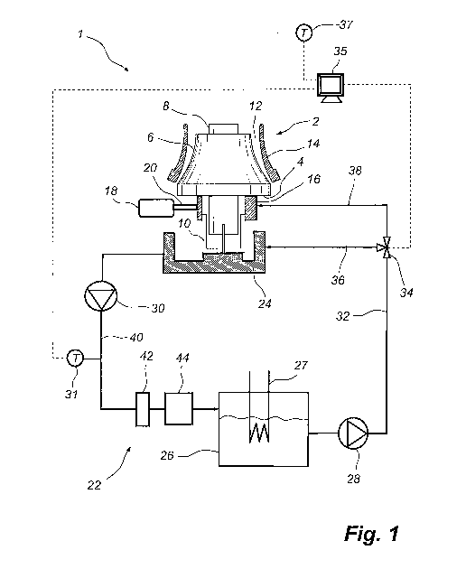
Fig. 1 is a schematic side view of a crushing apparatus comprising a
gyratory crusher.
CA 02721055 2010-10-08
WO 2009/126085 PCT/SE2009/000166
6
Fig. 2 is a three-dimensional view of an oil sump forming part of the
crushing apparatus shown in Fig. 1.
Fig. 3 is a three-dimensional view of the oil sump with a three-way
valve located in a first position.
Fig. 4 is a three-dimensional view of the oil sump with a three-way
valve located in a second position.
Description of Preferred Embodiments
Fig. 1 illustrates schematically a crushing apparatus 1. The crushing
apparatus 1 comprises a gyratory crusher 2. The gyratory crusher 2 com-
prises a crushing head 4, which supports a first crushing surface in the form
of an inner shell 6, and which is mounted on a crusher shaft 8. The crushing
head 4, which is mounted on the crusher shaft 8, can be moved in the vertical
direction by means of a hydraulic cylinder 10, which is connected to the lower
portion of the crusher shaft 8. The hydraulic cylinder 10 allows adjustment of
a gap 12 formed between the inner shell 6 and a second crushing surface in
the form of an outer shell 14, which surrounds the inner shell 6. The gyratory
crusher 2 further comprises an eccentric 16, which is arranged to cause the
crushing head 4 to execute a gyratory movement, in a manner know per se in
the art. A motor 18 has a drive shaft 20 by means of which the motor 18 can
rotate the eccentric 16.
The crusher apparatus 1 has a lubricating system 22, which is
arranged to lubricate the gyratory crusher 2 with the aid of a lubricant, such
as lubricating oil. The lubricating system 22 comprises an oil sump 24, which
is arranged in the gyratory crusher 2 for collecting lubricating oil that has
been
pumped, inter alia, to the eccentric 16 for lubrication of the same. The lubri-
cating system 22 further has an oil reservoir 26, which is arranged to contain
lubricating oil, and a first pump 28, which is arranged to pump lubricating
oil,
inter alia, to the eccentric 16. A second pump 30 is arranged to pump lubri-
cating oil back from the oil sump 24 to the oil reservoir 26. The oil
reservoir 26
is provided with a heater 27, which may be, for example, an electric heater or
a hot-water heater and which may be used to heat the lubricating oil in those
instances when the ambient temperature is low. The lubricating system 22
CA 02721055 2010-10-08
WO 2009/126085 PCT/SE2009/000166
7
further has a line 32 through which the first pump 28 is able to pump lubri-
cating oil to a three-way valve 34. As will be described in more detail below,
the three-way valve 34 is arranged to conduct lubricating oil to the oil sump
24 via a line 36 and/or to the bearings of the crusher 2, for example slide
bearings arranged on the eccentric 16, via a line 38. The gyratory crusher 2
is
controlled by a control system in the form of a control computer 35, which is
also arranged to control the functioning of the three-way valve 34. The
control
computer 35 is arranged to receive information from a temperature gauge 37,
which measures the ambient temperature in the vicinity of the gyratory
crusher 2.
The second pump 30 sucks oil out of the oil sump 24 via a line 40 and
pumps the oil via a filter 42, which filters out metal particles et cetera
from the
lubricating oil, and via a cooler 44, which is arranged to cool the
lubricating oil
when the crusher 2 has reached its operating temperature, back to the oil
reservoir 26. A temperature gauge 31 is arranged to measure the tempera-
ture in the lubricating oil leaving the second pump 30.
According to an alternative embodiment, the lubricating oil may be
conducted from the oil sump 24 to the oil reservoir 26 by gravitation, i.e.
without the need for a second pump 30. In such a case it is important that the
oil sump 24 is located higher up than the oil reservoir 26, and that the line
40
is short, so that a sufficiently steep incline is obtained to enable the
lubricating
oil, also when cold, to flow down into the oil reservoir 26. Moreover, it is
suitable, in the absence of the second pump, for the filter 42 and the cooler
44 to be arranged on the line 32, so that the pump 28 can pump the lubri-
cating oil through the filter 42 and the cooler 44.
Fig. 2 shows the oil sump 24 in more detail. The oil sump 24 has a
central portion 46, which is arranged for connection to the crusher shaft 8
and
the hydraulic cylinder 10. An outer wall 48 delimits the space 50 in which the
lubricating oil is collected. The outer wall 48 seals against a frame, not
shown
in Fig. 2, which means that crushed material and dust are not able to pene-
trate into the space 50. The central portion 46 is provided with a sealing
ring
49, which prevents hydraulic oil from the hydraulic cylinder 10 shown
schematically in Fig. 1 from mixing with the lubricating oil in the space 50.
CA 02721055 2010-10-08
WO 2009/126085 PCT/SE2009/000166
8
Hence, the space 50 forms a closed space for lubricating oil only. In the
outer
wall 48, a connection 52 for supplying lubricating oil to the crusher and two
outlets in the form of connections 54, 56 for removing lubricating oil from
the
oil sump 24 have been provided. The three-way valve 34 is coupled to the
connection 52. In the embodiment shown in Fig. 2, the connection 56 is used
to remove lubricating oil from the oil sump 24, whereas the connection 54 is
blocked. The fact that the oil sump 24 has two connections 54, 56 for
removing lubricating oil, which connections 54, 56 are arranged on opposite
sides of the oil sump 24 and, thereby, are able to draw off lubricating oil in
two
different directions, offers the advantage that the connection closest to the
oil
reservoir 26 can be selected, which means that the oil can be conducted
along the shortest possible path from the oil sump 24 to the oil reservoir 26.
The oil sump 24 further has a protruding portion 58. This protruding
portion 58 is arranged to collect oil which has been supplied to the crusher's
bearings, for example the bearings of the eccentric 16 shown in Fig. 1, and
which then has been allowed to flow downwards to the drive shaft 20 shown
in Fig. 1 for lubrication of the same. A substantial part of the lubricating
oil that
is conducted to the bearings of the gyratory crusher 2 through the line 38
shown in Fig. 1 will flow down into the protruding portion 58 of the oil sump
24.
Fig. 3 illustrates how the lubricating system 22 shown in Fig. 1 func-
tions during cold starting. By "cold starting" is here meant that the gyratory
crusher 2 is to be started after having been switched off for a relatively
long
period of time, usually at least 4 hours, under low ambient temperature
conditions, usually an ambient temperature below 0 C.
The relevant temperature for determining whether a cold starting
procedure is executed or not is the starting temperature of the gyratory
crusher 2, i.e. the temperature in the bearings of the gyratory crusher 2
which
are to be lubricated by the lubricating oil. The starting temperature can be
measured directly, for instance by means of a temperature sensor mounted
inside the crusher, for example adjacent the bearings of the eccentric 16. It
is
often easier, however, to measure the ambient temperature, for example, and
use the ambient temperature as an indicator of the actual starting tempera-
CA 02721055 2010-10-08
WO 2009/126085 PCT/SE2009/000166
9
ture. A measurement of the ambient temperature is suitably combined with
information about how much time has passed since the operation of the
gyratory crusher was last terminated. This is because the crusher will have a
higher temperature than the surroundings for an hour or a few hours after the
operation was terminated.
Hence, when the control computer 35 shown in Fig. 1 has received
instructions from an operator stating that the gyratory crusher 2 is to be
started and, at the same time, has received information from the temperature
gauge 37 indicating that the ambient temperature is below a first threshold
value, for example below 0 C, and the control computer 35 is also in
possession of information indicating that the gyratory crusher 2 has been off
for more than a certain predetermined period of time, for example more than
4 hours, the control computer 35 will instruct the three-way valve 34 to
assume a first position and to start the heater 27, which heats the
lubricating
oil in the reservoir 26. When the oil in the reservoir 26 has been heated to
the
desired temperature the first pump 28 is started and begins to pump oil to the
three-way valve 34. In this way, a flow of lubricant oil, referred to as OIN
in
Fig. 3, will be pumped to the three-way valve 34.
In its first position the three-way valve 34 is arranged to conduct, via
the line 38 shown in Fig. 1, a first sub-volume OBI of the lubricant oil flow
OIN
to the bearings of the gyratory crusher 2. In Fig. 3, this first sub-volume
OBI is
illustrated by a dashed line. A second sub-volume OREC of the lubricating oil
flow OIN is conducted via the line 36 shown in Fig. 1 directly to the space 50
in the oil sump 24. This second sub-volume, referred to as OREC in Fig. 3
and indicated by a continuous arrow,, will leave the space 50 relatively
quickly
via the line 40 shown in Fig. 1. The second sub-volume OREC constitutes 30-
100% of the lubricating oil flow OIN, and even more preferred 50-100% of the
lubricating oil flow OIN. The first sub-volume OBI amounts to the remaining
part, if any, of the lubricating oil flow OIN. Hence, the first sub-volume OBI
may be at most 70% of the lubricating oil flow OIN, in the case where the
second sub-volume OREC constitute 30% of the lubricating oil flow OIN, but
the first sub-volume OBI may also be 0% of the lubricating oil flow OIN, i.e.
CA 02721055 2010-10-08
WO 2009/126085 PCT/SE2009/000166
non-existent, in the case where the second sub-volume OREC constitutes
100% of the lubricating oil flow OIN.
Thus, the three-way valve 34 divides the incoming lubricating oil flow
OIN into a first sub-volume OBI, which is conducted to the crusher's bearings,
5 and a second sub-volume OREC, which is bypassed around the crusher's
bearings and which is therefore not cooled in the bearings. The second sub-
volume OREC should constitute 30-100% of the lubricating oil flow OIN that is
pumped to the three-way valve 34.
The lubricating oil of the first sub-volume OBI that has passed the
10 bearings of the crusher 2 flows down into the space 50 in the oil sump 24
in
the form of a flow OBO, as illustrated by a dashed arrow in Fig. 3. The flow
OBO is collected in the space 50 and leaves the sump 24 via the line 40
together with the second sub-volume OREC in the form of a common
lubricating oil flow GOUT. The lubricating oil of the first sub-volume OBI
passes the bearings of the gyratory crusher 2 and is heavily cooled due to its
passage through the bearings of the cold crusher 2. Because a substantial
part of the lubricating oil flow OIN will be conducted, in the form of the
second
sub-volume OREC, through the crusher 2 without being cooled in the
crusher's bearings, i.e. without passing the bearings, the temperature of the
oil flow OOUT will be relatively high, as compared with what would have been
the case had the whole lubricating oil flow OIN been caused to pass through
the crusher's bearings. As a result, the oil that reaches the second pump 30,
as shown in Fig. 1, will be considerably more fluid and easy to handle and the
risk of operational disturbances in the filter 42 and the cooler 44 caused by
cold, highly viscous oil will be significantly reduced. In addition, it is
ensured,
owing to the second sub-volume OREC, that a flow of lubricating oil will
always be conducted to the second pump 30 in conjunction with the starting
procedure, which is something that cannot be guaranteed in prior art, since in
prior art it may take quite some time for the oil that has been pumped to the
crusher's bearings to reach the second pump under cold-starting conditions.
Fig. 4 illustrates how the lubricating system 22 shown in Fig. 1
functions once the lubricating oil has become warm. The control computer 35,
as shown in Fig. 1, is capable of receiving a signal from the temperature
CA 02721055 2010-10-08
WO 2009/126085 PCT/SE2009/000166
11
gauge 31. When the lubricating oil has reached a certain temperature, for
example 30 C, the control computer 35 instructs the three-way valve 34 to
assume a second position. As an alternative, the control computer 35 may
instruct the three-way valve 34 to assume the second position when a certain
predetermined time, for example 2 minutes, has passed after the gyratory
crusher 2 was put into operation, or after the supply of lubricating oil to
the
three-way valve 34 was initiated.
In the second position of the three-way valve 34 at least 90% of the
lubricating oil flow, and even more preferred the whole lubricating oil flow,
is
conducted to the bearings of the gyratory crusher 2. Thus, the lubricating oil
flow, referred to as OIN in Fig. 4, will be pumped to the three-way valve 34,
as
shown in Fig. 4, and this entire flow is conducted to the bearings through the
line 38 shown in Fig. 1, in the form of the flow OBI, indicated by a
continuous
arrow in Fig. 4. After having passed the bearings of the crusher 2, the lubri-
cating oil flows down into the oil sump 24 in the form of the flow 0130, as
illustrated by a continuous arrow in Fig. 4, which flow OBO is collected in
the
space 50 and leaves the sump 24 via the line 40 shown in. Fig. 1 in the form
of an oil flow OOUT shown in Fig. 4.
Accordingly, in conjunction with cold starting of the gyratory crusher 2
the control computer 35 will control, during an initial phase, the three-way
valve 34 to assume a first position, in which the second sub-volume OREC of
the lubricating oil flow OIN is conducted directly to the oil sump 24 and
further
on to the second pump 30, as illustrated in Fig. 3, and will then, once the
lubricating oil is warm, control the three-way valve 34 to assume a second
position, in which the whole lubricating oil flow is conducted through the
bearings of the crusher 2, as illustrated in Fig. 4.
Starting of the motor 18, and thereby initiation of rotation of the
eccentric 16, may occur on different occasions. According to a first
alternative
embodiment, starting of the motor 18 is allowed only when the three-way
valve 34 has assumed its second position, i.e. only when at least 90% of the
lubricating oil flow, and even more preferred the whole lubricating oil flow,
is
conducted to the bearings of the gyratory crusher 2, as has been described
above with reference to Fig. 4. According to this first alternative
embodiment,
CA 02721055 2010-10-08
WO 2009/126085 PCT/SE2009/000166
12
heating of the lubricating oil to the operating temperature thus occurs while
the motor 18 and the eccentric 16 are idle. According to a second alternative
embodiment, starting of the motor 18 is allowed already when the three-way
valve 34 is in its first position, i.e. while the second sub-volume OREC of
the
lubricating oil flow OIN is conducted via the line 36 shown in Fig. 1 directly
to
the space 50 in the oil sump 24, as has been described above with reference
to Fig. 3. In this second alternative embodiment, the first sub-volume OBI,
which is conducted to the bearings of the crusher 2, is suitably greater than
0% of the lubricating oil flow with the three-way valve 34 in its first
position
and, more specifically, the first sub-volume OBI is suitably about 20-60% of
the lubricating oil flow OIN in order to provide lubrication of, inter alia,
the
bearings of the eccentric 16 also when the three-way valve 34 is in its first
position.
It will be appreciated that a number of modifications of the embodi-
ments described above are possible within the scope of the invention, as
defined by the appended claims.
It has been described above how a three-way valve is used to
apportion the lubricating oil flow between the lines 36 and 38. It will be
appreciated that other valve mechanisms may be used for this purpose. For
example, two two-way valves may be combined to provide the same function.
However, a three-way valve offers a particularly compact and simple design.
Another possibility is to use a single two-way valve. In this case, this
single
two-way valve is used to open and close the line 36 shown in Fig. 1. When
this single two-way valve is open, i.e. is in its first position, the pressure
drop
and the pressure head in the line 38 will cause 30-100% of the lubricating oil
flow OIN to be conducted directly to the oil sump 24 in the form of the flow
OREC. When such a single two-way valve is closed, i.e. shifts to its second
position, the whole lubricating oil flow OIN will be conducted to the
crusher's
bearings, in the form of the flow OBI, via the line 38.
The apparatus described above may be used for different types of
gyratory crushers, including gyratory crushers which have a rotary crusher
shaft with a crushing head fixedly mounted thereon, and gyratory crushers
which have a fixed crusher shaft and a crushing head adapted to rotate about
the fixed crusher shaft.
CA 02721055 2010-10-08
WO 2009/126085 PCT/SE2009/000166
13
It has been described above that the three-way valve can be instructed
to shift from its first position to its second position after a certain period
of time
has passed since the starting procedure was initiated, or when the lubricant
leaving the oil sump has reached a certain temperature. It will be appreciated
that these two indicators may be used independently of one another, or in
combination, and that other indicators adapted to indicate when the three-way
valve is to shift from its first to its second position may be used.
The disclosures in the Swedish patent application No. 0800823-7, from
which this application claims priority, are incorporated herein by reference.