Note: Descriptions are shown in the official language in which they were submitted.
CA 02721248 2015-11-12
1
Blood Treatment Apparatus
THE BACKGROUND OF THE INVENTION AND PRIOR ART
The present invention relates generally to extracorporeal blood treatment.
More particularly the invention relates to a blood treatment apparatus, a
method and a computer readable medium.
A conventional single-needle blood treatment apparatus, for instance a
hemodialysis system or a hemodiafiltration system, contains a dialysis fluid
circuit and a blood circuit with one or two blood pumps. For patient security
reasons, single-needle dialysis is advantageous in a self care setting.
Namely, here, there is no risk for dislodgement of a venous needle and
thereby loss of blood being pumped out unintentionally via an arterial
needle. Additionally, fewer needle punctures to the patient blood access
are required relative to dual-needle treatment. Generally, the single-needle
system is also well suited for long lasting treatments, such as nocturnal
treatments. Moreover, single-needle dialysis may be used when the patient
blood access is defective.
The prior art includes a range of examples of solutions for single-needle
blood treatment, as well as pump means adapted to such implementations.
For example, US 4,552,552 describes a dialysis pumping system for a
single-needle dialysis apparatus with a dialyzer having blood and dialysate
circuits, and wherein the blood inlets and outlets are joined by intake and
outtake lines with at least one blood connection. The intake line has a
CA 02721248 2010-10-13
WO 2009/127624 PCT/EP2009/054406
2
ving pump and pump valves placed upstream and downstream of
the blood pump. The blood pump unit has a generally stiff
housing with a diaphragm therein walling off the space in the
housing into a first chamber for blood and a second chamber for
driving fluid that is joined up with the driving pump. A respective
high and low pressure limiting valve means prevent pressure le-
vels outside a given interval by venting the working chamber
whenever the pressure falls outside predetermined threshold va-
lues.
US 6,645,166 reveals a blood treatment device and disposable
kit for a blood treatment device, e.g. a dialysis machine, which
permits both single- and dual-needle operation. Here, a blood
treatment unit has an inlet connected to a feed line and an outlet
connected to a return line. The feed line has two parallel line
branches, where a positive displacement pump is connected to a
first line branch, and a negative displacement pump is connec-
ted to a second line branch. Moreover, a connection line is pro-
vided to produce a fluid connection between the outlet of the
blood treatment unit and one of the two pumps. For single-need-
le operation, the feed and return lines are brought together and
connected to a common needle.
US 6,899,693 discloses a compact pulsating pumping unit inclu-
ding means suitable to draw blood from an intake connector in
order to send it to an outlet connector. Said means are contai-
ned in an enclosure provided with valves connected to the inlet
and the outlet. An elastic membrane here separates the enclo-
sure into two domes. This allows a working fluid to act on one
side of the membrane, such that the membrane acts on blood lo-
cated on the opposite side. The membrane thereby controls the
operation of an inlet valve and an outlet valve, such that blood
is moved into respective out from a pumping chamber.
Although the above solutions may have specific beneficial cha-
racteristics, they fail to provide an overall optimal fluid flow in a
blood treatment apparatus. For example attaining a desired level
CA 02721248 2010-10-13
WO 2009/127624 PCT/EP2009/054406
3
of ultrafiltration is complicated. Moreover, operating the appara-
tus requires pressure measurements on the blood side. Hence,
the design of the apparatus is compelled to be relatively intrica-
te, and handling the apparatus becomes impractical. This, in
turn, renders the apparatus unsuitable for a self care setting. In
this respect, the present invention is also advantageous becau-
se it requires relatively few interfaces between the apparatus
and the disposable units thereof. Furthermore, blood pressure
measurements on the blood side are problematic due to the
potential risk of infection and contamination of the blood via the
pressure measuring means. Specifically, in a self care setting,
the patient risks to be stricken with infections caused by his/her
own blood residuals from earlier treatments, whereas in a hos-
pital environment infectious substances may be transferred from
one patient to another.
SUMMARY OF THE INVENTION
The object of the present invention is therefore to alleviate the
above problems and provide an efficient and yet uncomplicated
blood treatment solution, which is well adapted for home/self
treatment environment.
According to the invention, the object is achieved by the appa-
ratus as initially described, wherein the fluid pumps are
configured to control the operation of the blood pumps via the
blood treatment fluid. The apparatus is further configured to
operate according to a cyclic process of which during a first
phase the untreated blood is extracted from the blood source,
and during a second phase the treated blood is delivered to the
target vessel.
In the apparatus according to the invention the flow of untreated
blood extracted from the blood source (access flow) is equivalent
to a difference between the second fluid flow of used blood
treatment fluid ejected from the apparatus and the first fluid flow
of fresh blood treatment fluid drawn from the fluid reservoir.
CA 02721248 2015-11-12
4
Likewise, in the apparatus according to the invention the flow of treated
blood to the target vessel is equivalent to a difference between the first
fluid
flow of fresh blood treatment fluid drawn from the fluid reservoir and the
second fluid flow of used blood treatment fluid ejected from the apparatus.
Moreover, the apparatus includes a flow control means configured to control
a trans-membrane flow between the blood side and the fluid side of the
blood treatment unit, and fluid paths connecting the pair of blood pumps to
the blood treatment unit.
The proposed blood treatment apparatus is advantageous because it
renders adjustment of for example the ultrafiltration level a straightforward
task.
According to an embodiment of the invention, each of the blood pumps
includes a pumping chamber. A flexible member separates the pumping
chamber into a first accumulation container and a second accumulation
container. The flexible member is movable within the pumping chamber so
as to vary a volume relationship between the first and second accumulation
containers. The second accumulation container is configured to receive an
amount of working fluid to act on the flexible member and thus pump blood
to and from the first accumulation container. Moreover, the fluid pumps and
the blood pumps are arranged such that the blood treatment fluid cons-
titutes the working fluid for the blood pumps.
According to one embodiment of the invention, the flow control means
includes a first flow restrictor that is configured to cause a first pressure
drop during operation of the apparatus. The first flow restrictor is arranged
in series with the blood treatment unit in a conduit system configured to
pass blood through the blood treatment unit. Optionally, the apparatus like-
wise includes a second flow restrictor. This flow restrictor is arranged in
series with the blood treatment unit in a conduit system configured to pass
blood treatment fluid through the blood treatment unit.
----------------------------------------------------------------- During
operation of the apparatus, the second flow restrictor is
CA 02721248 2010-10-13
WO 2009/127624 PCT/EP2009/054406
configured to cause a second pressure drop. It is further
preferable if, during operation of the apparatus, a pressure drop
on the blood side of the blood treatment unit and the second flow
restrictor is equal to the pressure drop on the fluid side of the
5 blood treatment unit and the first flow restrictor. Thus the
respective pressure drop may be set such that an appropriate
flow is achieved on the respective side of the blood treatment
unit, i.e. such that a trans-membrane flow is attained.
The flow restriction is also configured to provide for
synchronized operation of the blood pumps, i.e. the flexible
members of the first and second blood pumps reach their
respective end positions simultaneously. In operation, when the
blood pumps have reached their respective end positions, the
fluid pumps may be operated to adjust the trans-membrane flow,
i.e. to supply or withdraw fluid from the blood.
According to another embodiment of the invention, the
apparatus includes a control unit configured to control the fluid
pumps to be operated in such a manner that a base flow is
constituted. The base flow is constituted by a flow of blood
treatment fluid passing through the blood treatment unit during
both the first and second phases of the cyclic process, i.e. the
base flow is not passed through the blood pumps. In an
alternative embodiment of the invention the base flow in the first
phase of the cyclic process is different from the base flow in the
second phase of the cyclic process. The base flow is
independent of the flow of untreated blood extracted from the
blood source. The base flow is also independent of the flow of
treated blood delivered to the target vessel. The base flow may
be used together with one or more flow control means to control
the blood pumps to operate in a synchronized manner by
securing the same flow of blood treatment fluid to and from the
first and the second accumulation container, respectively. A
synchronized operation of the blood pumps ensures that
undesired transients in the trans-membrane flow are avoided.
CA 02721248 2010-10-13
WO 2009/127624 PCT/EP2009/054406
6
According to still another embodiment of the invention, the base
flow may be adjusted during the treatment. A feedback signal
received by the control unit includes a blood pressure
measurement. The blood pressure measurement is used to
control the blood treatment fluid pumps to provide a base flow
permitting synchronized operation of the blood pumps. More
specifically the feed back signal gives input on when the flexible
member in the blood pump reaches its end position by
identifying a blood pressure peak. The blood pressure may be
measured on a conduit configured to pass fresh blood treatment
fluid. Alternatively the blood pressure may be measured by
means of a blood pressure meter on a conduit configured to
pass blood. The magnitude of the base flow may be chosen
such that the flow on the blood treatment fluid side of the blood
treatment unit and on the blood side of the blood treatment unit
is more or less equal. In yet another embodiment of the
invention the base flow is chosen such that there is a significant
difference between the blood treatment fluid flow and the blood
flow.
According to yet another embodiment of the invention, the flow
control means includes a pair of auxiliary fluid pumps arranged
in a conduit system configured to pass blood treatment fluid
through the blood treatment unit. Each of the auxiliary fluid
pumps is configured to influence a flow of blood treatment fluid
that is passed through the blood treatment unit. Specifically, it is
preferable if a first auxiliary fluid pump is arranged in an outlet
conduit downstream of the blood treatment unit, and the first
auxiliary fluid pump is configured to withdraw fluid from the blood
being passed through the blood treatment unit. Analogously, a
second auxiliary fluid pump is optionally arranged in an inlet
conduit upstream of the blood treatment unit. The second auxi-
liary fluid pump is configured to supply fluid to the blood being
passed through the blood treatment unit. Consequently, in
operation the pair of auxiliary fluid pumps may be used to control
the trans-membrane flow. Since the flow of blood treatment fluid
CA 02721248 2010-10-13
WO 2009/127624 PCT/EP2009/054406
7
to the blood pumps is controlled by the fluid pumps,
synchronized operation of the blood pumps may be provided for
without any base flow.
According to a further embodiment of the invention, the flow
control means includes first and second adjustable flow rest-
rictors and first and second fluid valve means. The first
adjustable flow restrictor is arranged in a first blood-treatment-
fluid conduit upstream of the blood treatment unit. The first
blood-treatment-fluid conduit is parallel to a conduit in which a
first fluid pump of said fluid pumps is arranged. Analogously, the
second adjustable flow restrictor is arranged in a second blood-
treatment-fluid conduit downstream of the blood treatment unit,
and the second blood-treatment-fluid conduit is parallel to a
conduit in which the second fluid pump of said fluid pumps is
arranged. In this context, parallel means that the second blood-
treatment-fluid conduit and the conduit in which the second fluid
pump is arranged constitute two branches that originate from a
common point. Furtheron, the first fluid valve means is arranged
upstream the fist adjustable flow restrictor and the first fluid
pump in the inlet conduit configured to receive fresh blood
treatment fluid into the apparatus. The second fluid valve means
is arranged downstream the second adjustable flow restrictor
and the second fluid pump in an outlet conduit configured to
discharge used blood treatment fluid from the apparatus. By
adjusting, during operation, the first and second adjustable flow
restrictors and by opening and closing the first and the third fluid
valve means alternatingly in the first and second phase
respectively of the cyclic process, a desired trans-membrane
flow may be attained.
According to a further embodiment of the invention, the flow
control means includes four fluid valve means, which are
controllable in response to a respective valve control signal, e.g.
originating from the control unit. A first fluid valve means is
arranged on an inlet conduit configured to receive fresh blood
treatment fluid into the apparatus. Downstream of the first fluid
CA 02721248 2010-10-13
WO 2009/127624 PCT/EP2009/054406
8
valve means the inlet conduit is further connected to the first
fluid pump via a first fluid conduit. Downstream of the first fluid
valve means the inlet conduit is also further connected to the
blood treatment unit via a second fluid conduit means. A third
fluid valve means is arranged on the second fluid conduit means
between the first fluid valve means and the blood treatment unit.
A second fluid valve means is arranged on an outlet conduit
configured to discharge used blood treatment fluid from the
apparatus. The second fluid valve means is arranged
downstream of the blood treatment unit, and is also connected
to the second fluid pump. A fourth fluid valve means is arranged
on a conduit between the blood treatment unit and the second
fluid valve means. By opening and closing, during operation, the
first and the third fluid valve means alternatingly in the first and
second phase respectively of the cyclic process, and opening
and closing the second and fourth fluid valve means
intermittently, a desired trans-membrane flow may be attained.
According to another aspect of the invention the object is achie-
ved by the method described initially, wherein the method invol-
ves: controlling the blood pumps to operate by passing blood
treatment fluid through the fluid pumps, controlling the appara-
tus according to a cyclic process of which untreated blood is
extracted from the blood source during a first phase and treated
blood is delivered to the target vessel during a second phase,
and controlling a trans-membrane flow between the blood side
and the fluid side of the blood treatment unit through the medium
of a flow control means. The advantages of this method, as well
as the embodiments thereof, are apparent from the discussion
above with reference to the proposed apparatus.
According to a further aspect of the invention the object is
achieved by a computer program, which is directly loadable into
the memory of a computer, and includes software adapted to
control the method proposed above when said program is run on
a computer.
CA 02721248 2016-07-04
9
According to another aspect of the invention the object is achieved by a
computer readable medium, having a program recorded thereon, where the
program is to control a computer to perform the method proposed above
when the program is loaded into the computer.
More particularly, according to that aspect, the invention provides a
computer readable medium, having a program recorded thereon, where the
program is to make a computer control a blood treatment apparatus
including: a blood treatment unit configured to receive untreated blood and
fresh blood treatment fluid, and emit treated blood and used blood treatment
fluid, the blood being passed on a blood side of a semi-permeable membrane
structure and the blood treatment fluid being passed on a fluid side of said
structure; a pair of fluid pumps configured to pass blood treatment fluid
through the blood treatment unit; and a pair of blood pumps configured to
extract untreated blood from a bag, pass extracted blood through the blood
treatment unit and deliver treated blood to another bag, wherein fluid paths
connects the pair of blood pumps to the blood treatment unit, wherein the
program is to make the computer controlling the blood pumps to operate by
passing blood treatment fluid through the fluid pumps, controlling the
apparatus according to a cyclic process wherein during a first phase the un-
treated blood is extracted from the bag and during a second phase the trea-
ted blood is delivered to the another bag, and controlling a trans-membrane
flow between the blood side and the a fluid side of the blood treatment unit
through the medium of a flow control means, when the program is loaded into
the computer.
According to a further aspect, the invention provides a blood treatment
apparatus, comprising:
a blood treatment unit configured to receive untreated blood and
fresh blood treatment fluid, and emit treated blood and used blood
treatment fluid, the blood being passed on a blood side of a semi-
permeable membrane structure and the blood treatment fluid being
passed on a fluid side of said structure,
a pair of fluid pumps configured to pass blood treatment fluid
through the blood treatment unit, and
a pair of blood pumps configured to extract untreated blood from a
blood source (S), pass extracted blood through the blood treatment unit
and deliver treated blood to a target vessel (T),
a control unit, characterized in that
CA 02721248 2016-07-04
9a
the fluid pumps are configured to control the operation of the
blood pumps via the blood treatment fluid,
the apparatus is configured to operate according to a cyclic
process of which during a first phase the untreated blood is extracted
from the blood source (S), and during a second phase the treated blood
is delivered to the target vessel (T),
the apparatus comprises a flow control means (Rb, Rf; 16a, 16b;
Rf1, Rf2; V11, V12, V211 V22) configured to control a trans-membrane flow
between the blood side and the fluid side of the blood treatment unit,
and
wherein the apparatus includes fluid paths connecting the pair of
blood pumps to the blood treatment unit.
Clearly, the invention is applicable to dual-needle implementations.
However, the proposed solution is especially advantageous for blood
treatment in the form of single-needle hemodialysis or hemodiafiltration. The
solution is particularly suitable for self care treatment, daily/nocturnal
dialysis and intensive care. Further advantages, beneficial features and
applications of the present invention will be apparent from the following des-
cription and the dependent claims.
BRIEF DESCRIPTION OF THE DRAWINGS
The present invention is now to be explained more closely by means of
embodiments, which are disclosed as examples, and with reference to the
attached drawings.
Figures la-b
show block diagrams over a blood treatment apparatus
according to a first embodiment of the invention during a first and a
second phase respectively of a cyclic treatment process;
Figure 2
shows a pair of graphs which elucidate a relationship between a
set of pressure drops according to the first embodiment of the inven-
tion illustrated in Figures la and 1 b;
Figures 3a-b show
block diagrams over a blood treatment apparatus
according to a second embodiment of the invention during a first and a
second phase respectively of the proposed cyclic treatment process;
Figures 4a-b
show block diagrams over a blood treatment appa-
ratus according to a third embodiment of the invention during a
first and a second phase respectively
CA 02721248 2010-10-13
WO 2009/127624 PCT/EP2009/054406
of the proposed cyclic treatment process;
Figures 5a-b show block diagrams over a blood treatment appa-
ratus according to a fourth embodiment of the in-
vention during a first and a second phase res-
5 pectively of the proposed cyclic treatment process;
Figures 6a-b show block diagrams illustrating the measurement
of a trans-membrane flow between the blood side
and the a fluid side of the blood treatment unit in
the fourth embodiment of the invention;
10 Figure 7 shows graphs exemplifying how a flow of input
fresh blood treatment fluid and a flow of output
used blood treatment fluid may vary over time ac-
cording to one embodiment of the invention;
Figure 8 shows a graph illustrating how a trans-membrane
flow between a blood side and a fluid side of the
blood treatment unit may vary over time according
to one embodiment of the invention;
Figure 9 shows a graph exemplifying a pump-chamber blood
volume as a function of time according to one em-
bodiment of the invention; and
Figure 10 illustrates, by means of a flow diagram, a general
method of operating a blood treatment apparatus
according to the invention.
DESCRIPTION OF EMBODIMENTS OF THE INVENTION
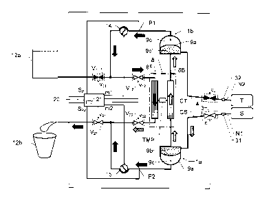
We refer initially to Figure 1a, which shows a block diagram over
a blood treatment apparatus (e.g. a dialysis apparatus) accor-
ding to a first embodiment of the invention during a first phase
of a proposed cyclic blood treatment process.
The apparatus includes a blood treatment unit 8 (typically repre-
sented by a dialyzer), first and second fluid pumps 14 and 15
respectively and first and second blood pumps 1a and lb res-
CA 02721248 2010-10-13
WO 2009/127624 PCT/EP2009/054406
11
pectively. First and second blood valve means 3 and 4 respecti-
vely are also included, which are controlled to be open and clo-
sed in an alternating fashion, such that the first blood valve
means 3 is open when the second blood valve means 4 is clo-
sed, and vice versa.
The blood treatment unit 8 has a blood side 8B and a fluid side
8F that are separated by means of a semi-permeable membrane
structure. For example, this structure may be represented by a
large number of hollow fibers whose walls constitute a respec-
tive semi-permeable membrane and which fibers are configured
to transport blood. The structure is also configured to allow
blood treatment fluid to be passed outside said fibers when
blood is transported there through. Naturally, the opposite situa-
tion is equally well applicable, i.e. that blood treatment fluid is
passed through the fibers and blood is passed outside thereof.
In any case, blood treatment (e.g. dialysis) takes place over
each fiber's semi-permeable membrane. Hence, the blood
treatment unit 8 is configured to receive untreated blood and
fresh blood treatment fluid, and emit treated blood and used
blood treatment fluid.
The fluid pumps 14 and 15 are configured to pass blood treat-
ment fluid through the blood treatment unit 8. The blood pumps
la and lb are configured to extract untreated blood from a blood
source S (e.g. a bag containing blood to be treated, or a patient),
pass extracted blood through the blood treatment unit 8 and deli-
ver treated blood to a target vessel T (e.g. a bag for cleaned
blood, or a patient). Specifically, the apparatus is controlled to
operate according to a cyclic process of which during a first
phase untreated blood is extracted from the blood source S, and
during a second phase treated blood is delivered to the target
vessel T. According to the invention, the fluid pumps 14 and 15
are also configured to control the operation of the blood pumps
la and lb via the blood treatment fluid. The apparatus has a
flow control means configured to control a trans-membrane flow
between the blood side 8B and the fluid side 8F of the blood
CA 02721248 2010-10-13
WO 2009/127624 PCT/EP2009/054406
12
treatment unit 8. In the first embodiment of the invention illust-
rated in Figures 1a and 1 b, a first flow restrictor Rb represents
one component of the flow control means. The first flow restric-
tor Rb is arranged downstream of a treated-blood outlet from the
blood treatment unit 8 and upstream of the second blood pump
1 b, which in turn, is configured to deliver the treated blood to the
target vessel T. During operation of the blood treatment appara-
tus, the fluid side 8F is associated with a fluid pressure drop and
the blood side 8B is associated with a blood pressure drop.
During operation of the apparatus, the first flow restrictor Rb is
configured to cause a first pressure drop over the first flow
restrictor Rb. As will be explained below, this is advantageous
with respect to the proposed control of the trans-membrane flow
between blood side 8B and the fluid side 8F.
In an alternative embodiment of the invention a second flow
restrictor Rf is arranged upstream of the fluid side of the blood
treatment unit 8F. A further alternative embodiment of the
invention comprises a first as well as a second flow restrictor Rb,
Rf. The second flow restrictor will be described further below.
According to one embodiment of the invention, each of the blood
pumps la and lb includes a pumping chamber. A flexible mem-
ber 9a and 9a' (e.g. in the form of a soft/elastic membrane) se-
parates this pumping chamber into a first accumulation contai-
ner 9b and 9b' respectively, and a second accumulation contai-
ner 9c and 9c' respectively. The flexible member 9a and 9a' is
movable within its pumping chamber so as to vary a volume re-
lationship between the first and second accumulation containers
9b, 9b' and 9c, 9c' respectively. Furthermore, each second ac-
cumulation container 9c and 9c' is configured to receive an
amount of working fluid to act on the flexible member 9a and 9a'
respectively, and thus pump blood through the first accumulation
container 9b and 9b' respectively. According to the invention,
the fluid pumps 14 and 15 respectively and the blood pump la
and lb are arranged relative to one another, such that the blood
treatment fluid constitutes the working fluid for the blood pumps
CA 02721248 2010-10-13
WO 2009/127624 PCT/EP2009/054406
13
la and lb. Hence, the fluid pumps 14 and 15 control the ope-
ration of the blood pumps la and lb via the blood treatment
fluid.
During a first phase of the cyclic blood treatment process
(Figure la), the second fluid pump 15 is configured to
extract/suck fresh blood treatment fluid from the second
accumulation container 9c of the first blood pump 1a and draw
this blood treatment fluid through the fluid side 8F of the blood
treatment unit 8. The operation of the second fluid pump 15 also
causes used blood treatment fluid to be extracted/sucked from
the second accumulation container 9c' of the second blood
pump lb. After passing the second fluid pump 15, this blood
treatment fluid is discharged from the apparatus, e.g. into the
drain or a waste compartment 12b.
The first fluid pump 14 is configured to draw blood treatment
fluid (e.g. dialysis fluid) from a fluid source, such as a reservoir
compartment 12a in a second phase of the cyclic blood
treatment process (Figure 1b). Optionally, during the first phase
of the cyclic blood treatment process illustrated in Figure la, the
first fluid pump 14 draws a relatively small flow of blood
treatment fluid (also referred to as base flow which will be
further described below), and pumps this fluid directly to a drain
or waste compartment 12b via a fluid side 8F of the blood
treatment unit 8 (and optionally via a second flow restrictor Rf,
which will be described below). Here, the operation of the first
and second fluid pumps 14 and 15 causes a trans-membrane
flow from the fluid side 8F to the blood side 8B of the blood
treatment unit 8. .
The above-mentioned first blood valve means 3 is configured to
control the extraction of untreated blood from the blood source S
via a first needle connector 31 and a first needle N1 . Analo-
gously, the above-mentioned second blood valve means 4 is
configured to control the delivery of treated blood to the target
vessel T via a second needle connector 32 and a second needle
CA 02721248 2010-10-13
WO 2009/127624 PCT/EP2009/054406
14
N2. Of course, in a single-needle implementation the first and
second blood valve means 3 and 4 are instead both connected
to one needle, which is attached to a patient's blood system.
In any case, during the first (or blood extraction) phase of the
cyclic blood treatment process illustrated in Figure 1a, the first
blood valve means 3 is open and the second blood valve means
4 is closed. As a result, when the second fluid pump 15 pulls the
fresh blood treatment fluid out from the second accumulation
container 9c of the first blood pump 1a, untreated blood is
extracted from the blood source and fed into the first accu-
mulation container 9b of the first blood pump la. Incoming blood
also continues into the blood side 8B of the blood treatment unit
8. Moreover, since the second fluid pump 15 also draws used
blood treatment fluid out from the second accumulation con-
tamer 9c' of the second blood pump 1 b, the blood located on the
blood side 8B of the blood treatment unit 8 is further pulled into
the first accumulation container 9b' of the second blood pump
lb. Hence, blood passes through the blood treatment unit 8, and
as a result, this blood is treated by the blood treatment fluid
passing through the fluid side 8F of the blood treatment unit 8.
Figure lb illustrates the second (or blood delivery) phase of the
cyclic blood treatment process. In this phase, the first blood
valve means 3 is closed while the second blood valve means 4
is open. The blood valve means 3 and 4 are controlled via a
respective control signal c1 and c2 generated by a control unit
20, which will be discussed in more detail below. In any case, in
contrast to the first phase, during the second phase the first fluid
pump 14 draws a relatively large flow of fresh blood treatment
fluid from the reservoir compartment 12a. The thus extracted
blood treatment fluid continues into the second accumulation
container 9c of the first blood pump la. The entry of fresh blood
treatment fluid into the second accumulation container 9c of the
first blood pump la, in turn, causes untreated blood located in
the first accumulation container 9b of the first blood pump 1a to
be pushed through the blood side 8B of the blood treatment unit
CA 02721248 2010-10-13
WO 2009/127624 PCT/EP2009/054406
8.
Moreover, the operation of the first fluid pump 14 causes fresh
blood treatment fluid to be extracted/sucked from the reservoir
compartment 12a. This blood treatment fluid continues directly
5 into the fluid side 8F of the blood treatment unit 8 (possibly via
the above-mentioned flow restrictor Rf). After passing the blood
treatment unit 8, the blood treatment fluid continues into the
second accumulation container 9c' of the second blood pump
lb. This, in turn, causes blood located in the first accumulation
10 container 9b' of the second blood pump lb to be ejected into the
target vessel via the blood valve means 4, the second needle
connector 32 and the second needle N2.
Optionally, during the second phase of the cyclic blood treat-
ment process, the second fluid pump 15 is also operated to
15 some extent. This causes a fraction (a base flow) of the used
blood treatment fluid to exit directly from the blood treatment
unit 8 (i.e. without being temporarily stored in any of the blood
pumps 1a, 1b). The operation of the first and second fluid pumps
14 and 15 during the second phase causes a trans-membrane
flow from blood side 8B to the fluid side 8F of the blood
treatment unit 8. Thus, by controlling first and second fluid
pumps 14 and 15 an amount of fluid drawn from the blood
passing through the blood treatment unit 8 may be adjusted.
The first and the second fluid pumps 14, 15 may, as mentioned
above, be operated in such a manner that a base flow is
constituted. The base flow is constituted by a flow of blood
treatment fluid passing through the blood treatment unit 8 during
both the first and second phases of the cyclic process, i.e. the
base flow is not passed through the blood pumps la, lb. The
base flow is independent of the flow of untreated blood
extracted from the blood source, S. The base flow may be used
together with one or more flow control means to control the
blood pumps la, lb to operate in a synchronized manner by
securing the same flow of blood treatment fluid to and from the
CA 02721248 2010-10-13
WO 2009/127624 PCT/EP2009/054406
16
first and the second accumulation container 9c, 9c',
respectively. Furtheron, the base flow may be used together
with one or more flow control means to control the trans-
membrane flow.
As mentioned above the blood treatment apparatus may
comprise a first flow restrictor Rb. The embodiment shown in
Figure 1 a and lb also comprises a second flow restrictor Rf
which is arranged in series with the blood treatment unit 8 in a
conduit system configured to pass blood treatment fluid through
the blood treatment unit 8. As mentioned above, during
operation of the apparatus, the first flow restrictor Rb is
configured to cause a first pressure drop and the second flow
restrictor Rf is configured to cause a second pressure drop. The
pressure drops over the first and second flow restrictors Rb and
Rf are desirable because it facilitates creation of an appropriate
trans-membrane flow. The pressure drops over the first and
second flow restrictors Rb and Rf are also desirable because it
facilitates synchronization of the blood pumps la and lb, i.e.
that the flexible members 9a and 9a' are allowed to reach their
respective end positions simultaneously.
Optionally, first and second motoric signals ml and m2 from the
control unit 20 control the operation of the fluid pumps 14 and
15 respectively.
Moreover, first and second pressure parameters are optionally
measured via a first pressure sensor signal Sp i registered on a
conduit configured to pass fresh blood treatment fluid from the
fluid container 12a into the apparatus, and a second pressure
sensor signal Sp 2 registered on a conduit configured to dischar-
ge used blood treatment fluid from the apparatus. For reasons of
simplicity, we here assume that a pressure measuring unit is
included in a control unit 20. In any case, the pressure mea-
suring unit does not come into contact with the blood. Instead,
the blood pressure is measured via the blood treatment fluid,
which due to the contact with the flexible members 9a and 9a'
CA 02721248 2010-10-13
WO 2009/127624 PCT/EP2009/054406
17
respectively has a pressure level equal to that of the blood.
Specifically, the first pressure parameter represents a first pres-
sure level of the untreated blood extracted from the blood
source S, and the second pressure parameter represents a se-
cond pressure level of the treated blood being delivered to the
target vessel T.
It is further advantageous if the control unit 20, in response to
the pressure sensor signals Sp i and Sp2 (expressing the first
and second pressure parameters), is configured to control the
first and second blood valve means 3 and 4, such that the
proposed cyclic process is effected. Of course, this control also
involves controlling the fluid pumps 14 and 15 via the motoric
signals m1 and m2 respectively. Specifically, during the first
phase (the blood extraction phase), the control unit 20 is confi-
gured to generate a first control signal c1 such that the first
blood valve means 3 is opened, a second control signal c2 such
that the second blood valve means 4 is closed. The control unit
further produces motoric signals m1 and m2 such that the
fluid pumps 14 and 15 are operated as desired. Then, during the
20 second phase (the blood delivery phase), the control unit 20 is
configured to generate the first control signal c1 such that the
first blood valve means 3 is closed, the second control signal c2
such that the second blood valve means 4 is opened, and
motoric signals m1 and m2 such that the fluid pumps 14 and 15
are operated as desired. The control unit 20 uses the first and
second pressure parameters to determine appropriate transi-
tions between the first and second phases, and thus control the
valve means 3, 4 and the fluid pump 14 and 15 as described
above. Optionally, the control unit 20, in turn, includes, or is
associated with; a memory means 21 storing computer software
for controlling the control unit 20 to effect the above-described
procedure.
In a start up phase (i.e. prior to initiating the above-mentioned
cyclic process) the fluid circuit may be filled (or more precisely
filled, such that superfluous fluid rinses the circuit) with fresh
CA 02721248 2010-10-13
WO 2009/127624 PCT/EP2009/054406
18
blood treatment fluid (e.g. dialysis fluid) from the fluid container
12a. The filling of the fluid causes any air in the dialysis fluid
circuit to be pushed into the waste compartment 12b (or drain)
where it is vented. Correspondingly, the first needle Ni may be
connected to a saline solution (or other appropriate fluid) to fill
and rinse, and thus eliminate any gas bubbles in the blood
circuit. This process of filling and rinsing the apparatus is nor-
mally referred to as priming.
Figure 2 shows an example of a first pressure Pgg along the
blood treatment unit 8 on the blood side 8B as a function of a
length L along the blood treatment unit 8. Figure 2 also exempli-
fies of a second pressure P8F along the blood treatment unit 8
on the fluid side 8F as a function of a length L along the blood
treatment unit 8. In this example, we assume that the blood
treatment unit 8 has length L = LgTu. A difference pressure AP is
defined as the difference between the first and the second
pressure points P1 and P2. In Figure 2, the first pressure drop
over the first flow restrictor Rf is designated APRf, and the
second pressure drop over the second flow restrictor Rb is
designated APRb.
A trans-membrane pressure drop TMP between the blood side
8B and the fluid side 8F of the blood treatment unit 8 is given by
the expression:
TMP = AP APRb AP APRf APRb APRf
2 2 2
In other words, by adequate selection of a combination of blood
treatment fluid flows in the first and second phases of the cyclic
process and the first and second pressure drops APRf and APRb
respectively (i.e. choosing the characteristics of the first and se-
cond flow restrictors Rf and Rb), a desired trans-membrane flow
can be attained and thereby ultrafiltration.
Figures 3a and 3b show block diagrams over a blood treatment
CA 02721248 2010-10-13
WO 2009/127624 PCT/EP2009/054406
19
apparatus according to a second embodiment of the invention
during a first and a second phase respectively of the proposed
cyclic treatment process. In Figures 3a and 3b all units and
components having reference signs, which also occur in Figures
1a and lb designate the same units and components as those
described above with reference to Figures la and lb.
The second embodiment differs from the first embodiment of the
invention in that the fluid pumps 14 and 15 are included in the
respective fluid paths which connect the blood pumps la and lb
to the blood treatment unit 8. In the second embodiment, the
first fluid pump 14 is arranged in a conduit between the second
blood pump lb and an inlet configured to receive fresh blood
treatment fluid into the blood treatment unit 8. Analogously, the
second fluid pump 15 is arranged in a conduit between the first
blood pump la and an outlet configured to emit used blood
treatment fluid from blood treatment unit 8. The fist and the
second fluid pumps 14, 15 may be controlled to supply and
withdraw the same flow to and from the first and the second
secondary accumulation containers 9c, 9c'.
Furthermore, the flow control means includes first and second
auxiliary fluid pumps 16a and 16b instead of the first and second
flow restrictors Rb and Rf. In this embodiment of the invention,
the first auxiliary fluid pump 16a is located in an outlet conduit
downstream of the blood treatment unit 8. The second auxiliary
pump 16b is located in an inlet conduit upstream of the blood
treatment unit 8. The auxiliary fluid pumps 16a and 16b are
configured to influence a flow of blood treatment fluid through
the blood treatment unit 8. More specifically the auxiliary fluid
pumps 16a, 16b may be adapted to the flows generated by the
fluid pumps 14, 15 and thereby control of the trans-membrane
flow during the cyclic process. Thus the blood treatment fluid
through the blood treatment unit, the blood flow and the trans-
membrane flow may be adjusted independently. In one
embodiment of the invention, during the first phase of the
proposed cyclic process, the first auxiliary fluid pump 16a is
CA 02721248 2010-10-13
WO 2009/127624 PCT/EP2009/054406
adapted to control the trans-membrane flow while the second
auxiliary pump 16b is idle and, and during the second phase of
the proposed cyclic process the second auxiliary fluid pump 16b
is adapted to control the trans-membrane flow while the first
5 auxiliary pump 16a is idle. This is illustrated in Figures 3a and
3b, where the auxiliary fluid pump 16a is controlled to operate
via a motoric signal m3, and the second auxiliary fluid pump 16b
is controlled to operate via a motoric signal m4 from the control
unit 20. The operation of the auxiliary fluid pumps 16a and 16b
10 causes more or less blood treatment fluid to be ejected into the
waste compartment 12b than what is stored in the accumulation
containers 9c and 9c' of the first and second blood pumps 1a
and lb respectively. This fluid may originate from the source
12a via the second auxiliary pump 16b, or from the blood side,
15 as a trans-membrane flow, or both. Hence the flow of blood
treatment fluid through the blood treatment unit 8 can be more
or less than what is controlled by the fluid pumps 14 and 15.
The task of auxiliary fluid pumps 16a and 16b is hence to
augment the flow through the blood treatment unit 8, as well as
20 to control the trans-membrane flow.
In this embodiment of the invention the first and the second
auxiliary pumps 16a, 16b may be operated such that the above
described base flow is constituted. However, the base flow is
not needed for synchronization of the blood pumps. The
magnitude of the base flow is chosen such that the flow on the
blood treatment fluid side 8F of the blood treatment unit 8 and
on the blood fluid side 8B of the blood treatment unit 8 is more
or less equal. Alternatively, the base flow is chosen such that
there is a significant difference between the blood treatment
fluid flow and the blood flow, e.g. the blood treatment fluid flow
is 500 ml/min and the blood flow is 300 ml/min
In an alternative embodiment of the blood treatment apparatus
shown in Figure 3a and 3b the first fluid pump 14 is arranged
upstream the second auxiliary pump 16b and the second fluid
pump 15 is arranged downstream the first auxiliary pump 16a in
CA 02721248 2010-10-13
WO 2009/127624 PCT/EP2009/054406
21
order to lessen any transients in the trans-membrane flow. In a
further alternative embodiment the first and the second fluid
pumps 14, 15 are both arranged upstream the second auxiliary
pump 16b or downstream the first auxiliary pump 16a in order to
lessen any transients in the trans-membrane flow.
Figures 4a and 4b show block diagrams over a blood treatment
apparatus according to a third embodiment of the invention
during a first and a second phase respectively of the proposed
cyclic treatment process. In Figures 4a and 4b all units and
components having reference signs, which also occur in Figures
la, 1 b, 3a and 3b designate the same units and components as
those described above with reference to Figures 1a, lb, 3a and
3b.
The third embodiment differs from the second embodiment of
the invention in that the flow control means instead of one or
more auxiliary fluid pumps, includes first and second adjustable
flow restrictors Rfl and Rf2 respectively. The first adjustable
flow restrictor Rfl is controllable in response to a first restriction
control signal rl from the control unit 20, and the second
adjustable flow restrictor Rf2 is controllable in response to a
second restriction control signal r2 from the control unit 20.
The first adjustable flow restrictor Rfl is arranged in a first
blood-treatment-fluid conduit upstream of the blood treatment
unit 8. The first blood-treatment-fluid conduit is parallel to a con-
duit in which a first fluid pump 14 is arranged. I.e. both the first
adjustable flow restrictor Rfl and the first fluid pump 14 are
connected to a conduit configured to receive incoming fresh
blood treatment fluid, however the first fluid pump 14 is further
connected to the second blood pump lb whereas the first ad-
justable flow restrictor Rfl is further connected to the blood
treatment unit 8.
The second adjustable flow restrictor Rf2 is arranged in a
second blood-treatment-fluid conduit downstream of the blood
CA 02721248 2010-10-13
WO 2009/127624 PCT/EP2009/054406
22
treatment unit 8. The second blood-treatment-fluid conduit is
parallel to a conduit in which the second fluid pump 15 of said
fluid pumps is arranged. In other words, both the second adjust-
able flow restrictor Rf2 and the second fluid pump 15 are con-
nected to a conduit configured to eject used blood treatment
fluid from the apparatus, however the second fluid pump 15 is
further connected to the first blood pump 1a whereas the second
adjustable flow restrictor Rf2 is further connected to the blood
treatment unit 8.
The third embodiment further differs from the second em-
bodiment of the invention in that the flow control means instead
of the auxiliary pumps 16a, 16b includes a first and second
valve means V11 and V21, where each valve means is
controllable in response to a respective valve control signal v11
and v21 from the control unit 20.
The first fluid valve means V11 is controllable in response to a
first valve control signal v11. The first fluid valve means V11 is
arranged on an inlet conduit configured to receive fresh blood
treatment fluid into the apparatus. Downstream of the first fluid
valve means V11 the inlet conduit is further connected to the first
fluid pump 14 via a first fluid conduit. Downstream the first fluid
valve means V11 the inlet conduit is also further connected to
the blood treatment unit 8 via a second fluid conduit means and
the first adjustable flow restrictor Rf1.
The second fluid valve means V21, is controllable in response to
a second valve control signal v21. The second fluid valve means
V21 is arranged on an outlet conduit configured to discharge
used blood treatment fluid from the apparatus. Specifically, the
second fluid valve means V21 is arranged downstream of the
blood treatment unit 8 via the second adjustable flow restrictor
Rf2. Further the second valve means V21 is connected to the
second fluid pump 15.
By controlling the first and the second valve means V11 and V215
CA 02721248 2010-10-13
WO 2009/127624 PCT/EP2009/054406
23
to alternatingly open and close during the respective first and
second phase of the cyclic process and controlling the
adjustable flow restrictors Rfl and Rf2 to appropriate values in
the first and second phases of the cyclic process, the trans-
membrane flow between the blood side 8B and the fluid side 8F
of the blood treatment unit 8 may be controlled in a manner
equivalent to that described above.
Figures 5a and 5b show block diagrams over a blood treatment
apparatus according to a fourth embodiment of the invention
during a first and a second phase respectively of the proposed
cyclic treatment process. In Figures 5a and 5b all units and
components having reference signs, which also occur in Figures
la, 1 b, 3a, 3b, 4a and 4b designate the same units and compo-
nents as those described above with reference to Figures 1a,
1 b, 3a, 3b, 4a and 4b.
The fourth embodiment differs from the third embodiment of the
invention in that the flow control means, instead of the
adjustable flow restrictors, includes a third and a fourth valve
means V12 and V22, where each valve means is controllable in
response to a respective valve control signal v12 and v22 from
the control unit 20.
The third fluid valve means V12, which is controllable in respon-
se to a second valve control signal v12, is arranged on the se-
cond fluid conduit between the first fluid valve means V11 and
the blood treatment unit 8.
The fourth fluid valve means V22, which is controllable in
response to the fourth valve control signal v22, is arranged on a
conduit between the blood treatment unit 8 and the second fluid
valve means V21.
Specifically, according to one embodiment of the invention, the
control unit 20 is configured to control the fluid valve means V11,
V12, V21 and V22 as follows. During the first phase (i.e. when
blood is being extracted from the blood source S), the control
CA 02721248 2010-10-13
WO 2009/127624 PCT/EP2009/054406
24
unit 20 controls the first fluid valve means V11 to a closed posi-
tion; the third fluid valve means V12 to an open position; and the
second valve means V21 to an open position. Moreover, the
control unit 20 controls the fourth fluid valve means V22 in an
intermittent manner, between an open and a closed position,
such that a desired trans-membrane flow is attained. This is
illustrated in Figure 5a.
Figure 5b illustrates the second phase (i.e. when blood is being
delivered to the target vessel T). During this phase, the control
unit 20 controls the first fluid valve means V11 to an open posi-
tion; the third fluid valve means V12 in an intermittent manner,
between an open and a closed position, such that a desired
trans-membrane flow is attained; the second valve means V21 to
a closed position; and control the fourth fluid valve means V22 to
an open position.
In order to keep track of the fluid balance between the untreated
and the treated blood (e.g. represented by blood extracted from
a patient and blood returned to the patient) it is important to
measure the trans-membrane flow in each phase of the cyclic
process. For example such measurements may be made based
on signals registered via first and second flow measurement
sensors 33 and 34 respectively (see Figures 6a and 6b).
Figures 6a and 6b show block diagrams, which illustrate how the
trans-membrane flow between the blood side 8B and the a fluid
side 8F of the blood treatment unit 8 is measured. In Figures 6a
and 6b all units and components having reference signs, which
also occur in Figures la, 1 b, 3a, 3b, 4a, 4b, 5a and 5b designa-
te the same units and components as those described above
with reference to Figures 1a, 1 b, 3a, 3b, 4a, 4b, 5a and 5b.
Here, we have chosen to describe the trans-membrane flow
measurement referring to the fourth embodiment of the inven-
tion. Nevertheless, the same principle is equally well applicable
to any one of the above-described first, second, or third embo-
diments of the invention, wherein the first measurement sensor
CA 02721248 2010-10-13
WO 2009/127624 PCT/EP2009/054406
33 is arranged in proximity to the inlet configured to receive
fresh blood treatment fluid into the apparatus, and the second
flow measurement sensor 34 is arranged in proximity to the
outlet configured to eject used blood treatment fluid from the ap-
5 paratus.
The proposed flow measurement during each phase involves (a)
registering a first amount A1 of blood treatment fluid fed into the
apparatus, and (b) registering a second amount A2 of fluid ejec-
ted from the apparatus. The first flow measurement sensor 33 is
10 configured to deliver the first amount A1 to the control unit 20,
and the second flow measurement sensor 34 is configured to
deliver the second amount A2 to the control unit 20. Based on
these parameters, the control unit 20 is configured to determine
an average trans-membrane flow as the difference between the
15 first and second amounts A1 and A2 divided by the duration of
the phase in question.
To enable measurement of the first and second amounts A1 and
A2 as well as a total amount of blood treatment fluid fed into the
apparatus, the third embodiment of the invention shown in Figu-
20 res 6a and 6b includes a set of additional fluid valve means V31,
V32, V33, and V34. For reasons of clarity, the figures 6a and 6b
do not show control lines to these means V31, V32, V33 and V34,
or to the valve means V12, V21 or V22. However, analogous to the
control signal v11 in respect of the first fluid valve means V11,
25 each of these fluid valve means is controllable via a respective
control signal transferred from the control unit 20.
During the first phase illustrated in Figure 6a (i.e. when blood is
being extracted from the blood source S), the control unit 20 is
configured to control a first additional fluid valve means V31 to
an open position; control a second additional fluid valve means
V32 to a closed position; control a third additional fluid valve
means V32 to a closed position; and control a fourth additional
fluid valve means V34 to an open position. The fluid valve means
V11, V12, V21 and V22 are controlled as described above with re-
CA 02721248 2010-10-13
WO 2009/127624 PCT/EP2009/054406
26
ference to Figure 5a.
During the second phase illustrated in Figure 6b (i.e. when blood
is being delivered to the target vessel T), the control unit 20 is
configured to control the first additional fluid valve means V31 to
a closed position; control the second additional fluid valve
means V32 to an open position; control the third additional fluid
valve means V33 to an open position; and control the fourth
additional fluid valve means V34 to a closed position. The fluid
valve means V11, V12, V21 and V22 are controlled as described
above with reference to Figure 5b.
Optionally, the control unit 20 is likewise configured to determi-
ne a respective amount of blood treatment fluid fed into the se-
cond accumulation container 9c' of the second blood pump lb
during the second phase of the cyclic process and delivered out
of the second accumulation container 9c of the first blood pump
la during the first phase of the cyclic process , as well as a total
amount of fluid fed into and taken out of the blood treatment
apparatus.
Figure 7 shows a first graph 014 exemplifying how a flow of input
fresh blood treatment fluid may vary over time t. Figure 7 also
shows a second graph 015 exemplifying how a flow of output
used blood treatment fluid may vary over time t. The duration of
one phase of the cyclic process is denoted Tph in Figure 7. Mo-
reover, Figure 7 illustrates an access flow FA as a difference
between the flow of input fresh blood treatment fluid and the
flow of output used blood treatment fluid. The access flow FA
represents a flow of blood extracted from the blood source S.
Figure 7 also shows a base flow level FB (dashed line), which
represents a minimum flow level. As can be seen, in this ex-
ample base flow level FB is approximately 20 ml/min.
According to one embodiment of the invention, the control unit
20 is configured to control the first fluid pump 14 to draw fresh
blood treatment fluid from the fluid reservoir 12a, control the
CA 02721248 2010-10-13
WO 2009/127624 PCT/EP2009/054406
27
second fluid pump 15 to eject used blood treatment fluid from
the apparatus, such that the access flow FA attains a desired le-
vel.
According to another embodiment of the invention, the control
unit 20 is configured to control the fluid pumps 14 and 15 to be
operated during the first and second phases of the cyclic blood
treatment process in such a manner that the flows 014, 015 of
blood treatment fluid passing through the blood treatment unit 8
is equal to or exceeds the base flow level F B during the first
phase as well as the second phase of this process. In a further
alternative embodiment of the invention the auxiliary pumps 16a,
16b are operated such that the blood treatment fluid passing
through the blood treatment unit 8 is equal to or exceeds the
base flow level F B during the first phase as well as the second
phase of this process.
Figure 8 shows a graph, which illustrates an example of the
trans-membrane flow QuF between the blood side 8B and the
fluid side 8F of the blood treatment unit 8 as a function of time t.
Here, the first phase of the cyclic process includes an extraction
period E during which an increasing amount of blood runs into
the first accumulation containers 9b and 9b' respectively of the
first and second blood pumps 1a and 1 b, and an extended ext-
raction period Eext during which the flexible membranes 9a and
9a' are (essentially) positioned in their respective first end posi-
tions, and thus no more blood may enter the first accumulation
containers 9b and 9b'. As a result, fluid is drawn from the blood
during this period Eext. Analogously, the second phase of the
cyclic process includes a delivery period D during which an in-
creasing amount of blood treatment fluid runs into the second
accumulation containers 9c and 9c' respectively of the first and
second blood pumps la and 1 b, and an extended delivery period
Dext during which the flexible membranes 9a and 9a' are (es-
sentially) positioned in their respective second end positions,
and thus no more blood treatment fluid may enter the second
CA 02721248 2010-10-13
WO 2009/127624 PCT/EP2009/054406
28
accumulation containers 9c and 9c'. As a result, during this pe-
riod Dext, fluid is transferred to the blood over the semi-perme-
able membrane. Hence, by adjusting the extended delivery pe-
riods Dext, an accumulated trans-membrane flow between the
blood side 8B and the fluid side 8F of the blood treatment unit 8
can be controlled.
Figure 9 shows a graph illustrating the amount of blood stored in
one of the blood pumps la or lb as a function of time t corres-
ponding to the trans-membrane flow Q u F of Figure 8. As is appa-
rent, the first accumulation container 9b or 9b' has a volume of
50 ml, and an interval t
.end-E during which the chamber 9b or 9b'
is completely filled with blood is somewhat shorter than an
interval t
.end-D during which the chamber 9b or 9b' is completely
empty (i.e. when the second accumulation container 9c or 9c' is
completely filled with blood treatment fluid).
To sum up, we will now describe the proposed method of opera-
ting a blood treatment apparatus with reference to the flow diag-
ram of Figure 10. Here, we presume that the blood treatment ap-
paratus includes: a blood treatment unit configured to receive
untreated blood and fresh blood treatment fluid, and emit treated
blood and used blood treatment fluid. Moreover, it is assumed
that the blood passes on a blood side of a semi-permeable mem-
brane structure and that the blood treatment fluid passes on a
fluid side of said structure. A pair of fluid pumps are configured
to pass blood treatment fluid through the blood treatment unit
and a pair of blood pumps are configured to extract untreated
blood from a blood source, pass extracted blood through the
blood treatment unit and deliver treated blood to a target vessel.
A first step 1010 opens a first valve means, and in parallel there
with a second step 1015 closes a second valve means. Here,
the first valve means controls an input of untreated blood from a
blood source, and the second valve means controls an output of
treated blood to a target vessel.
CA 02721248 2010-10-13
WO 2009/127624 PCT/EP2009/054406
29
Thereafter, a step 1020 controls first and second fluid pumps to
eject blood treatment fluid, which currently is located in the
blood pumps. A first fraction of the blood treatment fluid stored
in the second accumulation container of the first blood pump is
fresh and passes the blood treatment unit before being ejected
from the apparatus, and a second fraction of the blood treatment
fluid stored in the second accumulation container of the second
blood pump has already passed the blood treatment unit (i.e. is
used). As a result of the blood treatment fluid ejection, untreated
blood from the blood source is extracted. A first fraction of this
blood is stored untreated in the first accumulation container of
the first blood pump, and a second fraction of this blood is sto-
red after having passed the blood treatment unit (i.e. as treated)
in the first accumulation container of the second blood pump.
In parallel with step 1020, a step 1025 controls a trans-mem-
brane fluid flow between the blood side and the a fluid side of
the blood treatment unit. This may involve any one of the above-
described strategies, for instance exclusively controlling the first
and second fluid pumps (cf. the first embodiment of the inven-
tion).
Subsequently, a step 1030 checks whether or not the flexible
members of the first and second blood pumps have reached
their respective end positions. As described above, this conclu-
sion is optionally drawn based on pressure measurements on
the fluid side of the apparatus. If in step 1030 it is found that the
blood pumps' flexible members have not yet reached their end
positions, the procedure loops back to steps 1010 and 1020.
Otherwise, case steps 1040 and 1045 follow.
Step 1040 closes the first valve means, and in parallel there
with step 1045 opens the second valve means.
Thereafter, a step 1050 controls the first and second fluid
pumps to draw blood treatment fluid into the first and second
blood pumps. A first fraction of this fluid goes directly to the se-
CA 02721248 2010-10-13
WO 2009/127624 PCT/EP2009/054406
cond accumulation container of the first blood pump, and a se-
cond fraction of this fluid passes through the blood treatment
unit before entering the second accumulation container of the
second blood pump. As a result of the entry of blood treatment
5 fluid, treated blood is delivered to the target vessel. A first frac-
tion of this blood in the first accumulation container of the first
blood pump passes the blood treatment unit where it is treated,
and a second fraction of this blood located in the first accumu-
lation container of the second blood pump has already passed
10 the blood treatment unit and goes directly to the target vessel.
In parallel with step 1050, a step 1055 controls a trans-membra-
ne fluid flow between the blood side and the fluid side of the
blood treatment unit. Again, this may involve any one of the abo-
ve-described strategies.
15 Then, a step 1060 checks whether or not the flexible members
of the first and second blood pumps have reached their respec-
tive end positions. If this is found to be the case a step 1065 fol-
lows, and otherwise the procedure loops back to steps 1050 and
1055.
20 Step 1065 checks whether or not a desired trans-membrane
fluid transport has been accomplished between the blood side
and the fluid side of the blood treatment unit. If this is found to
be the case, the procedure loops back to steps 1010 and 1015,
and otherwise the procedure loops back to steps 1050 and 1055.
25 The procedure iterates as described above until the treatment is
finalized.
All of the steps, as well as any sub-sequence of steps, descri-
bed with reference to Figure 10, above may be controlled by
means of a programmed computer apparatus. Moreover, al-
30 though the embodiments of the invention described above with
reference to the drawings comprise computer apparatus and
processes performed in computer apparatus, the invention thus
also extends to computer programs, particularly computer pro-
CA 02721248 2010-10-13
WO 2009/127624 PCT/EP2009/054406
31
grams on or in a carrier, adapted for putting the invention into
practice. The program may be in the form of source code, object
code, a code intermediate source and object code such as in
partially compiled form, or in any other form suitable for use in
the implementation of the procedure according to the invention.
The program may either be a part of an operating system, or be
a separate application. The carrier may be any entity or device
capable of carrying the program. For example, the carrier may
comprise a storage medium, such as a Flash memory, a ROM
(Read Only Memory), for example a DVD (Digital Video/Versatile
Disk), a CD (Compact Disc), an EPROM (Erasable Program-
mable Read-Only Memory), an EEPROM (Electrically Erasable
Programmable Read-Only Memory), or a magnetic recording
medium, for example a floppy disc or hard disc. Further, the car-
rier may be a transmissible carrier such as an electrical or opti-
cal signal which may be conveyed via electrical or optical cable
or by radio or by other means. When the program is embodied in
a signal which may be conveyed directly by a cable or other
device or means, the carrier may be constituted by such cable
or device or means. Alternatively, the carrier may be an inte-
grated circuit in which the program is embedded, the integrated
circuit being adapted for performing, or for use in the per-
formance of, the relevant procedures.
In this specification, the wording that: "a fluid pump is arranged in
a conduit" shall be understood to also encompass arrangements
wherein the pump is configured to operate on a fluid passing
through the conduit by other means than having the pump ac-
tually included in the conduit, such as hose pumps manipulating
the exterior of a fluid conduit.
In this specification is exemplified that the first accumulation
container 9b or 9b' has a volume of 50 ml. However, the volume
may be smaller or larger, e.g. in the range of 25-75 ml.
The reference to any prior art in this specification is not, and
should not be taken as, an acknowledgement or any suggestion
CA 02721248 2010-10-13
WO 2009/127624 PCT/EP2009/054406
32
that the referenced prior art forms part of the common general
knowledge in Australia, or in any other country.
The term "comprises/comprising" when used in this specification is
taken to specify the presence of stated features, integers, steps or
components. However, the term does not preclude the presence or
addition of one or more additional features, integers, steps or
components or groups thereof.
The invention is not restricted to the described embodiments in the
figures, but may be varied freely within the scope of the claims.